
Microbrain Intelligent ITS-A08 Millimeter Wave Radar
Version history
| The date of | version | Version described |
| 2019.07.31 | 1.0 | Initializing creation |
| 2019.11.21 | 2.0 | Normal iteration |
| 2020.3.14 | 3.0 | Add calibration process and alarm mode changes |
A list
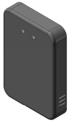
ITS-A08 is a set of system developed by Changsha Mozhibi Intelligent Technology Co., Ltd. for forward collision warning FCW, which gives early warning to dangerous targets in the lane directly ahead. Its unique ability to penetrate smoke, fog, and dust is available for allday, all-weather applications. ITS-A08 can detect targets as far as 80M. The alarm type includes 485 communication and IO level output. At the same time, it is necessary to access the body signal for comprehensive analysis and processing, and finally output the alarm signal, including one Level I and level II.
Product features
- spectrum: 77-81G
- appearance size: 107.5 * 73.2 * 18 mm
- waterproof level: IP67
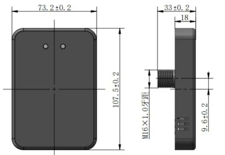
Unmarked dimensional tolerance: When ≤10mm, the tolerance is ±0.3mm;When between (10~50) mm, the tolerance is ±0.5mm;When ≥50mm, the tolerance is ±0.8mm.
Product parameters
The ITS-A08 radar adopts the FMCW modulation mode with high complexity and is accurate in the measurement range to determine the coordinates and velocity of the target relative to the radar.
| features | parameter | Technical indicators |
|
System property | Working voltage | 9-24V |
| Working temperature | – 40 ℃ ~ 85 ℃ | |
| Power consumption | < 2.5 W. | |
| Waterproof level | IP67 | |
| spectrum | 77-81G | |
| Communication interface | RS485 | |
| The shell size | 107.5 * 73.2 * 18 mm | |
| Horizontal beamwidth | Plus or minus 60 ° | |
| Detection performance | Distance resolution | 0.36 m |
| Ranging accuracy | Better than 0.18 m | |
| Detection range | 6m | |
| Communication interface | The input signal | 485 signal |
| The output signal | Two-channel IO port level /485 signal |
Product functions
Longitudinal stationary target recognition
The self-propelled vehicle moves forward at a constant speed in the center of the lane toward a stationary vehicle. The self-propelled vehicle starts one within a safe distance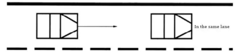
Identification of longitudinal moving targets
The self-propelled vehicle moves towards the vehicle ahead in the center of the lane at a speed greater than that of the moving vehicle ahead. The self-propelled vehicle will activate the first-level alarm within a safe distance and the second-level alarm within a dangerous distance.
Lateral target identification
The self-propelled vehicle and the target vehicle travel at the same speed in the center of the lane, and the vehicle in front of the adjacent lane slows down to a speed significantly lower than that of the self-propelled vehicle and the target vehicle in front; No alarm will be issued during overtaking.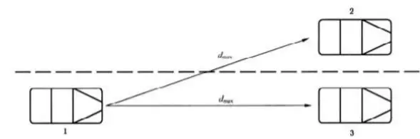
Instructions:
- Oneself car;
- The car in front of the adjacent lane;
- The target vehicle;
Identification of lateral target at bend
The self-propelled vehicle and the target vehicle are driving in the same lane at the same speed, and the workshop distance will not trigger the alarm. The vehicle in the adjacent lane will decelerate significantly lower than the self-propelled vehicle, and no alarm will be issued during the overtaking process.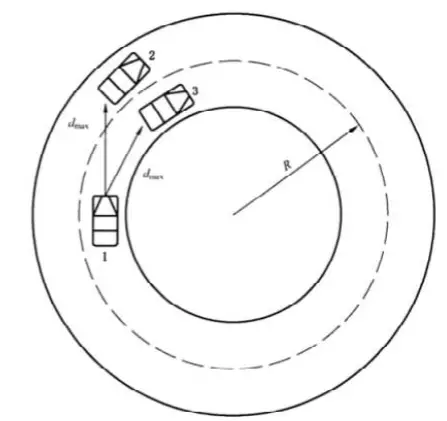
Instructions:
- Oneself car;
- The car in front of the adjacent lane;
- The target vehicle;
Interference recognition in adjacent areas
- According to the regulation of road clearance height in 2.0.7 of JTG B01-2014, the clearance height is 4.5m, and no alarm will be issued if the self-propelled vehicle drives under the target with a height of 4.5m;
- For speed bumps and manhole covers on the road, no alarm will be sent during the driving process;
- For the road test targets such as houses, fences and shelter forests on both sides of the road, self-driving cars will not be used during driving Send an alert.
Delivery list
| The serial number | The name of the accessories | The number of |
| 1 | radar | 1 |
| 2 | The M16 nut | 1 |
| 3 | gasket | 1 |
| 4 | Rubber waterproof ring | 1 |
| 5 | M3 tapping screw | 2 |
| 6 | Wire harness | 1 |
| 7 | Certificate of approval | 1 |
| 8 | The instructions | 1 |
| 9 | Radar installation hole location map | 1 |
Quick Use guide
Pin definition
| The serial number | Cable marking | Cable color | instructions |
| 1 | 12V | red | positive |
| 2 | GND | black | Power supply cathode |
| 3 | GND | yellow | Reserve common ground |
| 4 | B-/RX | white | TTL RX or 485 B- |
| 5 | A+/TX | gray | TTL TX or 485 A+ |
| 6 | Normally open 1 | blue | Normally open 1 |
| 7 | Normally open 1 | green | Normally open 1 |
| 8 | Normally open 2 | brown | Normally open 2 |
| 9 | Normally open 2 | purple | Normally open 2 |
| 10 | The input | orange | The input |
Radar installation location
It is recommended to install from 0.5 to 1.0m above the ground. If the installation height is less than 0.5m, the installation should be adjusted appropriately Pitching Angle; The installation position is attached to the logo position in front of the vehicle. The customer can reserve the installation hole position or for different vehicle types Make mounting bracket.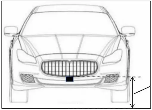
Output Agreement
Radar has two warning modes, one is IO output warning mode, the other is 485 output warning mode.
IO port output mode Radar warning protocol:In IO port output mode, the radar warning information is composed of warning lights and buzzers, and the warning level is determined by TTC (collision time, unit second) and absolute distance threshold L1 (unit meter). L1 is the range threshold detected by radar. Radar has a level two alert
| Alarm level | TTC, L(absolute distance) | Warning lights | buzzer |
| Level 1 | T < = > TTC and L L1 | Normally on | Drops off |
| The secondary | T < = TTC and L < L1 | flash | Drops off |
| There is no warning | T > TTC and L > L1 | There is no | There is no |
Note: The buzzer does not go off immediately when moving from level 1 to level 2 In the mode of output warning information, radar warning protocol: In this mode, the radar warning information 485 message is composed, baud rate is 115200, frame ID is the standard
| TTC,L | Whether early warning | 485 Output information |
| T > TTC and L > L1 | There is no warning | FA 00 00 00 00 00 00 FE |
| T < = > TTC and L L1 | Level 1 warning | FA 01 XX XX XX XX 00 FE |
| T < = TTC and L < L1 | Level 2 warning | FA 02 XX XX 00 00 00 FE | ||||||
| Data protocol | FA | 00 | AA | BB | CC | DD | 00 | FA |
| head | Y=0xAABB V=0xCCDD alarm level Distance =(y- 32768)/10 speed =(V-32768)/10 unit: m, step: 0.1 unit: m/s | The reserved | The tail | |||||
| No alarm | FA 00 00 00 00 00 00 FE | |||||||
| Level 1 warning | FA 01 XX XX XX XX 00 FE | |||||||
| Level 2 warning | FA 02 XX XX 00 00 00 FE | |||||||
| Note: For example, the data ID 0x401 received on the 485 bus: FA 01 80 66 7F CA 00 FE indicates that the radar gives early warning, the obstacle is in front of 10.2m, the speed is -5.4m /s, and the negative sign indicates approaching to the radar | ||||||||
Note: This radar needs to be connected to the vehicle 485 bus to obtain the vehicle speed from the bus. When the vehicle speed is greater than the starting speed, the radar will start to work. For the convenience of customer testing, the starting speed of the radar is 0 by default. If the starting speed needs to be set, the starting speed can be set with 485. The format of the set protocol is shown in the figure below:
| The frame ID | 0x201 | |
| The frame type | The standard frame | |
| Baud rate | 115200 | |
| Data protocol | 8C | AA |
| head | V = 0 xaa * 0.1 km/h | |
Radar early-warning output mode setting
The warning output mode of the radar can be set through the 485 bus. Select the 485 output mode or IO port output mode, and the radar defaults to IO port output mode. Connect the 485 bus of the radar with the 485 adapter, open the upper computer (or 485Test software) adapted to the 485 box, select the device model USB485-2E-U and baud rate Select 115200, other Settings can be set by default. The specific protocols are shown in the following table:
| The frame ID | 0x201 | |||
| The frame type | The standard frame | |||
| Baud rate | 115200 | |||
| Set the item | The data format | Data parsing | Set success return | Return after setting failure |
| Radar warning output mode | 88 A | A=0x00 A=0x01 | IO port output 485 output | 08 A | 88 A |
Radar boot self-test
The radar will conduct a self-check at startup. If the radar output mode is IO port output mode, the buzzer and the early-warning light will work twice at the same time at startup. If the model of radar output for 485 output, in 485 when the phone is switched on bus will receive ID 0 x201 messages, the message content is 0 x11, 0 x01, 0 x33, 0 x44, 0 x44, 0 x55. Whether the radar is self-checked on startup or not can be set through bus 485.
Acquisition of vehicle steering Angle by radar
The radar can obtain the vehicle’s steering Angle through the 485 bus. When the steering Angle information is not connected, the default Angle is 0.The agreement for radar acquisition of steering Angle is as follows:
| The frame ID | 0x80 | |||
| The frame type | The standard frame | |||
| Baud rate | 115200 | |||
| Set the item | The data format | Data parsing | Set success return | Return after setting failure |
| Acquire steering Angle | XX A XX XX XX XX XX XX | Right turn Angle = A – 0x80 left turn Angle = – a | There is no | There is no |
Radar acquisition of vehicle speed
The radar can get the vehicle speed through the 485 bus. When speed information is not connected, the default speed is 0. The agreement for radar to obtain vehicle speed is as follows:
| The frame ID | 0x215 | |||
| The frame type | The standard frame | |||
| Baud rate | 115200 | |||
| Set the item | The data format | Data parsing | Set success return | Return after setting failure |
| To get the speed of the car | A B XX XX XX XX XX XX | Speed = ((A<<8)+B) /100 | There is no | There is no |
Matters needing attention in product use
- power pin needs to separate external 12 v dc regulated power supply;
- using four M4 screws – A08;
- when installation, please keep the radome surface is clean, clean up the surface need with a soft wet cloth to wipe, and then the ran dry;
- installation please pay attention to the shape of the radar, ensure the installation radar not deformation, do not squeeze, knock against, it broke Play;
- installation as far as possible away from the frequent startup of high-power electrical equipment and motor has a strong magnetic field interference Buy;
- installation to ensure that the radar for the factory, not to tear open outfit. If an encounter in the installation process can not solve the problem, please contact changsha Mo ratio intelligent technology Co., LTD. Customer service personnel, we will serve you wholeheartedly!
Federal Communications Commission (FCC) Interference Statement
This equipment has been tested and found to comply with the limits for a Class B digital device, pursuant to Part15 of the FCC Rules. These limits are designed to provide reasonable protection against harmful interference in a residential installation. This equipment generates, uses, and can radiate radio frequency energy and, if not installed and used in accordance with the instructions, may cause harmful interference to radio communications. However, there is no guarantee that interference will not occur in a particular installation. If this equipment does cause harmful interference to radio or television reception, which can be determined by turning the equipment off and on, the user is encouraged to try to correct the interference by one of the following measures:
- Reorient or relocate the receiving antenna.
- Increase the separation between the equipment and receiver.
- Connect the equipment into an outlet on a circuit different from that to which the receiver is connected.
- Consult the dealer or an experienced radio/TV technician for help.
This device complies with Part 15 of the FCC Rules. Operation is subject to the following two conditions: (1) This device may not cause harmful interference, and (2) this device must accept any interference received, including interference that may cause undesired operation. FCC Caution: Any changes or modifications not expressly approved by the party responsible for compliance could void the user’s authority to operate this equipment.
RF exposure warning
This equipment complies with FCC radiation exposure limits set forth for an uncontrolled environment. This product may not be collocated or operated in conjunction with any other antenna or transmitter. This equipment must be installed and operated in accordance with provided instructions and the antenna(s) used for this transmitter must be installed to provide a separation distance of at least 20 cm from all persons and must not be collocated or operating in conjunction with any other antenna or transmitter.


