![]() AP-N505 3000 Mbps Indoor Access Point,
AP-N505 3000 Mbps Indoor Access Point,
User Guide  AP-N505
ENTERPRISE WI-FI 6 ACCESS POINT
Quick Start Guide V1.0
Introduction
Thank you for choosing the enterprise Wi-fi 6 access point. This guide is designed to familiarize you with the layout of the access point and describes how to deploy the access point in your network. 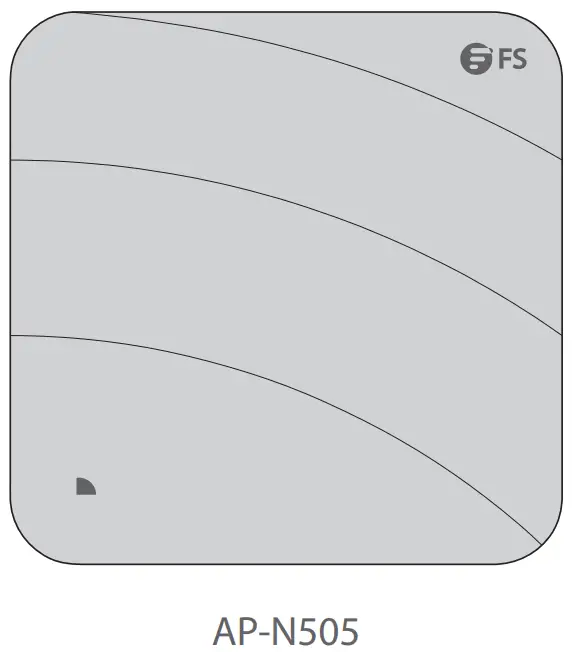
Accessories
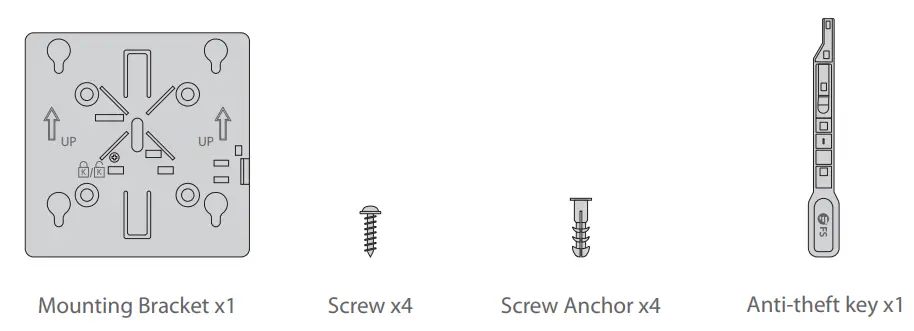 Optional (Not Included)’
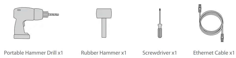
Hardware Overview
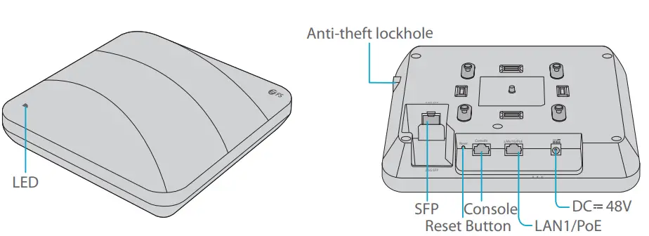
Ports
Port | Description |
| Anti-theft lockhole | Connect to the anti-theft lock. |
| SFP | An uplink fiber optical port for service data transmission. |
| CONSOLE | An RJ45 console port for serial management. |
| LAN1/PoE | An uplink adaptive Ethernet port for service data transmission. |
| IEEE 802.3af standard PoE power supply. | |
| DC 48V | DC adapter power supply. |
SFP Port
The device at the other end that connects to the SFP port of the AP can support both optical and electrical port types
| Rate (SFPport) | Rate (optical=module) | Negotiated Rate of the Device | |||
| 1G | 1G/10G/auto | 1G/2.5G/10G/auto | |||
| Optical Port | 1G | 3G | 1G | 1G | 1G |
| 1G | 1G | 1G | 1G | 1G | |
| 2.5G | 3G | / | / | 2.5G | |
| 2.5G | 1G | / | / | 2.5G | |
| Electrical Port | 1G | 2.5G | / | / | / |
| 1G | 1G | 1G | 1G | 1G | |
| 2.5G | 2.5G | / | / | 2.5G | |
| 2.5G | 1G | / | / | / |
![]() NOTE:
NOTE:
- The SFP port of AP does not support negotiated rate. When using the optical module, the rates of the AP, the optical module and the device at the other end must be the same.
- The AP supports optical&electrical uplink port multiplexing. If optical and electrical uplink ports connect to cables at the same time, the AP will preferentially select the optical uplink port as the data transmission port (automatically disables the electrical uplink port). When the optical uplink port cable is removed, the electrical uplink port automatically starts
Button
| Button | Description |
| Reset | Restart: Press the “Reset” button for less than 2 seconds. |
| Restore to Factory Default Settings: Press and hold the “Reset” button for more than 3 seconds. |
LED
FIT AP
| State | Frequency | Description |
| Off | N/A | AP is not connected to the power supply, or AP is in DND state, which can be closed by software. |
| Blinking Green | 3Hz | Uboot program initialization in progress. |
| Solid Green | N/A | Main program initialization in progress. |
| Blinking Red | 3Hz | Initialization is complete, but both Ethernet links are down. |
| Double Blinking RED | 2Hz | AP location, used to locates the current AP model( AP-N505E). |
| Solid Orange | N/A | Initialization is complete, and AP is establishing a CAPWAP. |
| Blinking Orange | 3Hz | Program update in progress under FIT Mode. Do not power AP off. |
| Solid Blue | N/A | AP is working normally and the CAPWAP is in normal state. No wireless client is associated with AP. |
| Blinking Blue | 3Hz | AP is working normally and the CAPWAP is in normal state. At least one wireless client is associated with AP. |
FAT AP
| State | Frequency | Description |
| Off | N/A | AP is not connected to the power supply, or AP is in DND state, which can be closed by software. |
| Blinking Green | 3Hz | Uboot program initialization in progress. |
| Solid Green | N/A | Main program initialization in progress. |
| Blinking Red | 3Hz | Initialization is complete, but both Ethernet links are down. |
| Solid Blue | N/A | AP is working normally. No wireless client is associated with AP. |
| Blinking Blue | 3Hz | AP is working normally. At least one wireless client is associated with AP. |
![]() NOTE: Hz indicates the number of times a flashing light blinks per second.
NOTE: Hz indicates the number of times a flashing light blinks per second.
Installation Requirements
- Install AP indoors. Do not power AP on during installation.
- Ensure that the installation site is dry and flat.
- Ensure that the installation position is secure enough.
- Ensure that AP avoid liquid intrusion.
- Ensure that the space around the installation position is enough to facilitate heat dissipation and maintain(more than 0.4m).
- Install AP in a well-ventilated position.
- The working environment must maintain a certain temperature and humidity.
- Keep AP clean and dust-free.
- Keep AP away from high voltage cables.
- Keep AP away from strong thunderstorms and electric field environment.
Installation
Connecting the PoE Power Supply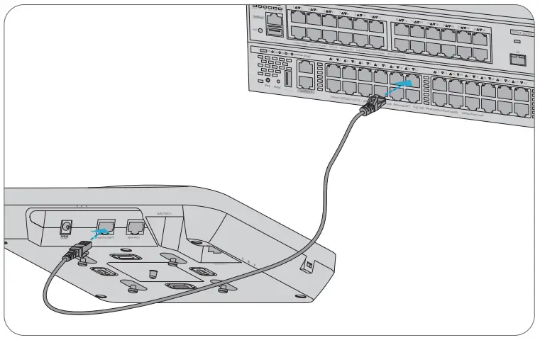 Connect the LAN1/PoE port of the AP to a PoE switch with an Ethernet cable.
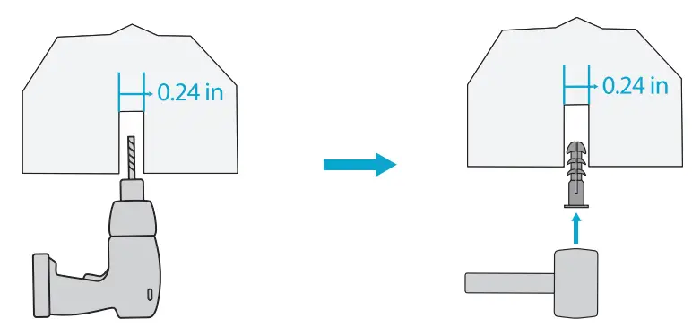
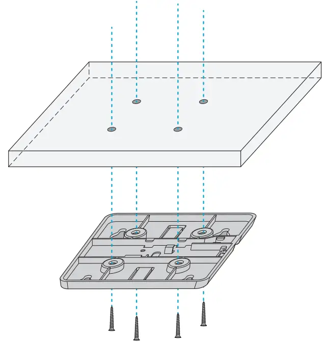
Ceiling Mount
- Drill 4 mounting holes of 6mm(0.24 in) diameter into the desired positions of ceiling with a center distance of 53mm(2.09 in).

- Insert screw anchors into each hole separately, hit and fix them with a rubber hammer.

- Align the 4 holes at the back of the mounting bracket with the screw anchors and fix the screws to the mounting bracket with a screwdriver.

- Align the buckles behind the AP with the buckle holes of the mounting bracket and push the AP into the holes in the opposite direction of the arrow to fix.
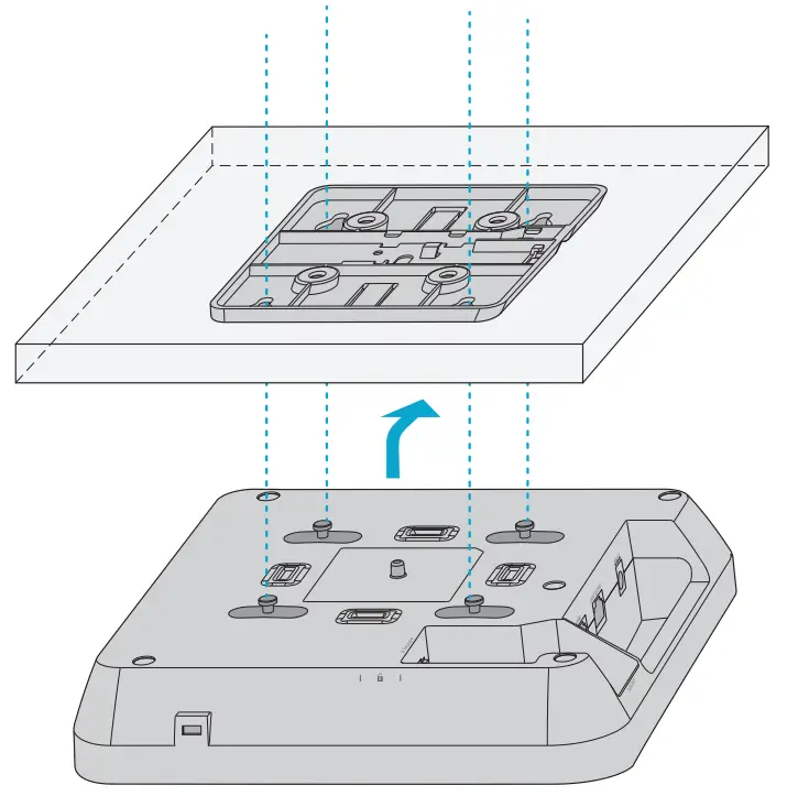
![]() NOTE:
NOTE:
- Connect the Ethernet cable before mounting the AP on the bracket.
- The AP should be pushed into the buckle holes smoothly.
- After mounting, check whether the AP is fixed.
- The steps of wall mount are the same as the ceiling mount.
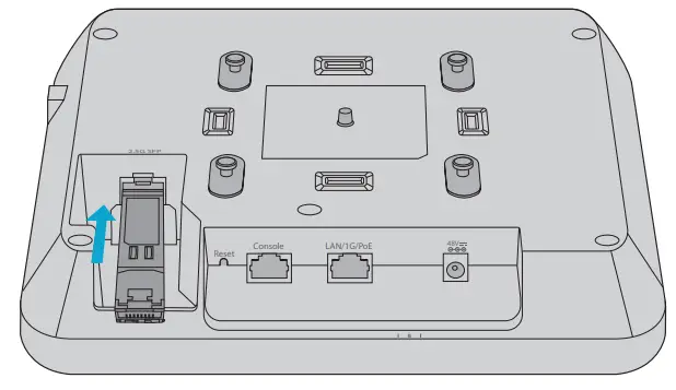
Installing the Optical Transceiver Module
- Insert the module into the SFP port.

- Insert one connector of a fiber cable into the module.


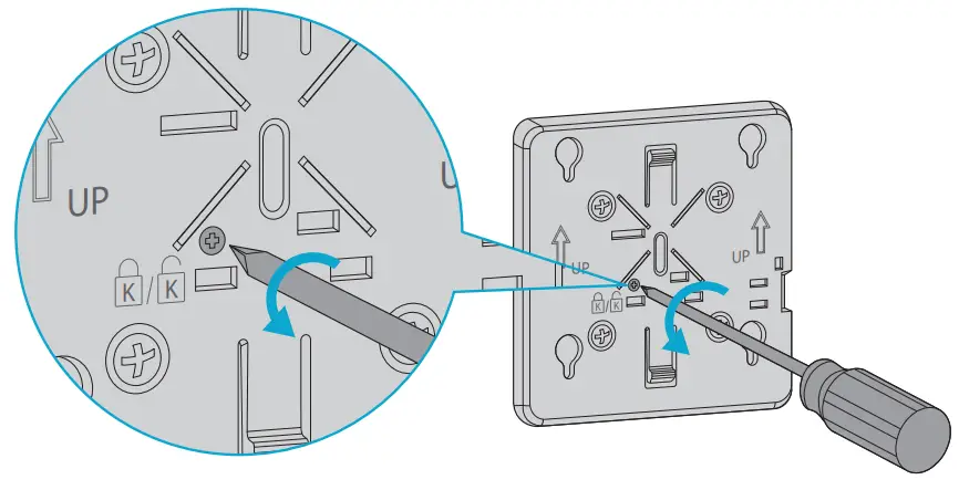
(Optional) Enabling the Anti-theft Lock
 Remove the screws on the mounting bracket with a screwdriver and enable anti-theft lock.
- Align the buckles behind the AP with the buckle holes of the mounting bracket and push the AP into the holes in the opposite direction of the arrow to fix.
 Remove the screws on the mounting bracket with a screwdriver and enable anti-theft lock.
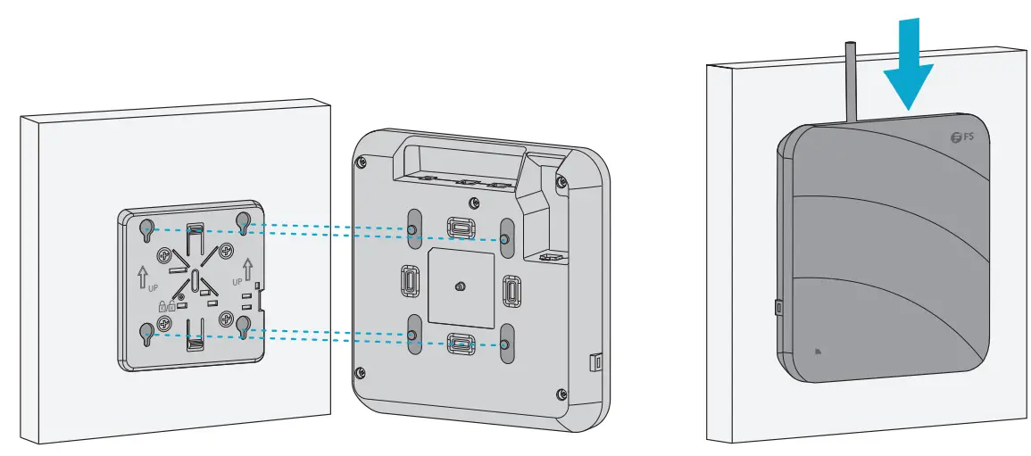
Dismounting the AP
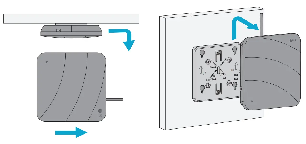 For both ceiling mount and wall mount, hold two sides of the AP and push it in the direction of the network port to release it from the buckle holes.
Configuring the Access Point
Configuring the AP via the Web-based Interface
Step 1: Connect a computer to the business port of the AP using the network cable.
Step 2: Set the IP address of the computer to “192.168.1.x” (“x” is any number from 2 to 254).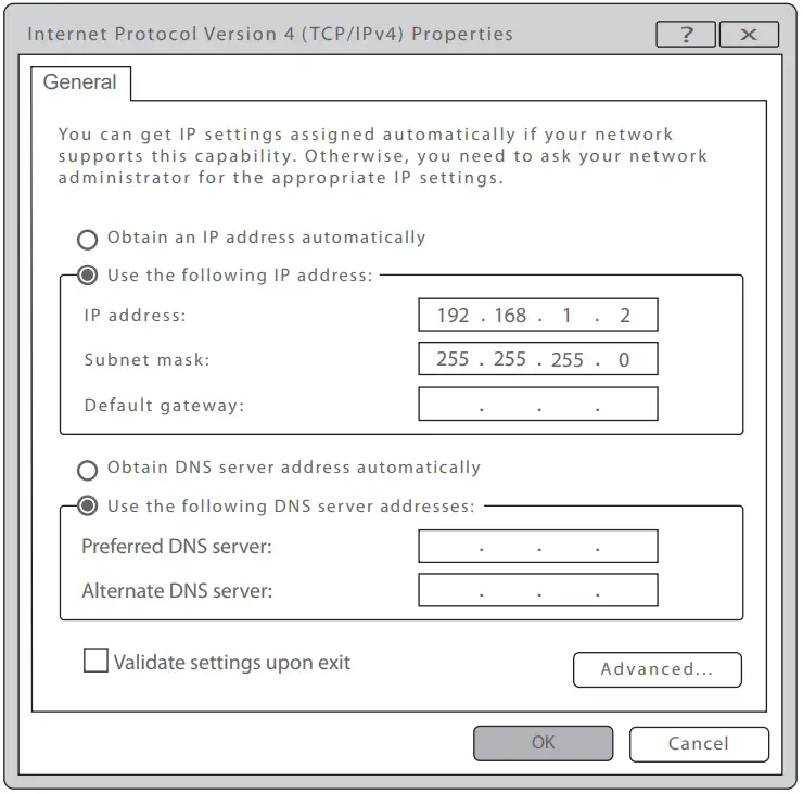 Step 3: Open a browser, type “http://192.168.1.1” and enter the default user name and password (both are “admin”)
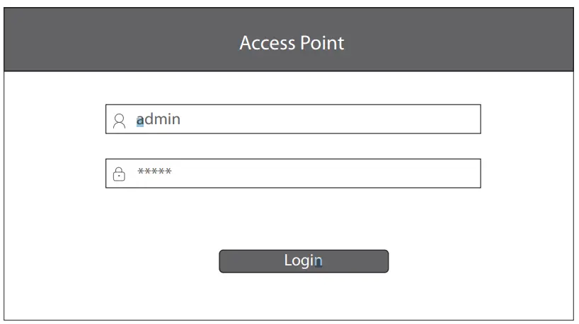 Step 4: Click “Login” to display the web-based configuration page.
Step 5: Click “System Mode Switch” to switch the FIT/FAP working mode. 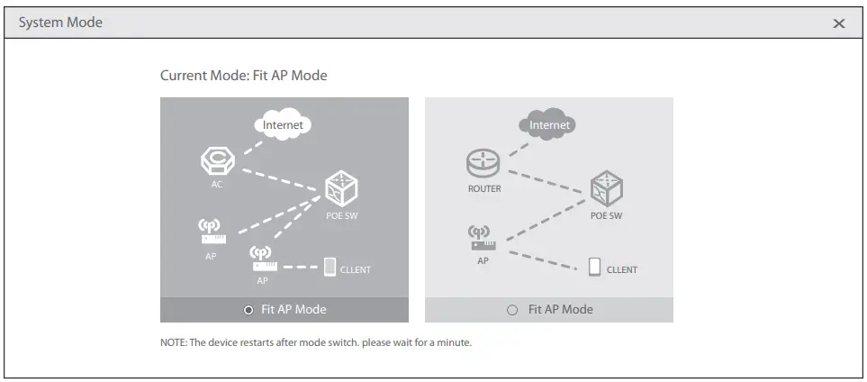
![]() NOTE: The AP works in Fit AP Mode by default.
NOTE: The AP works in Fit AP Mode by default.
Configuring the AP via the Console Port (FAT AP Mode)
Step 1: Connect a computer to the AP’s console port using the console cable.
Step 2: Start the terminal simulation software such as “HyperTerminal” on the computer.
Step 3: Set the parameters of the “HyperTerminal”: 9600 bits per second, 8 data bits, no parity, 1 stop bit and no flow control.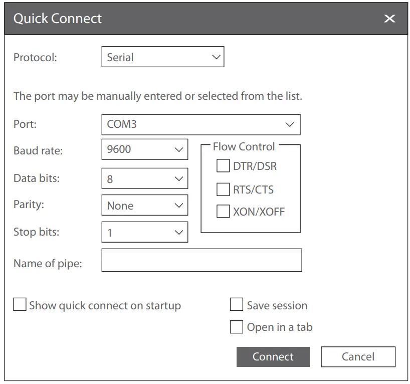 Step 4: After setting the parameters, click “Connect” to enter. And then enter the password (“admin” by default).
![]() NOTE: For more details, please refer to the Configuration Guide on the website.
NOTE: For more details, please refer to the Configuration Guide on the website.
Troubleshooting
The screen displays request timed out
- Check whether the network cable is intact.
- Check whether the hardware connection is correct.
- Check whether the IP address setting of the computer is correct.
- Check whether the indicators of AP and the computer are normal.
LED is off after the AP is powered on
- For PoE power supply, check whether the power source is IEEE 802.11af/at compliant, or whether the Ethernet cable is properly connected.
- For DC adapter power supply, check whether the adapter is connected to an active power outlet, or whether the adapter works properly.
Ethernet port is not working after connecting
Check whether the device at the other end of the Ethernet cable is working properly, the Ethernet cable is capable of providing the required data rate, or it is properly connected.
Wireless client cannot find the AP
- Check whether the power supply works properly.
- Check whether the Ethernet port is properly connected.
- Check whether the AP is correctly configured.
- Move the client device to adjust the distance between the client and the AP.
Online Resources
Download https://www.fs.com/products_support.html
Help Center https://www.fs.com/service/fs_support.html
Contact Us https://www.fs.com/contact_us.html
Product Warranty
FS ensures our customers that any damage or faulty items due to our workmanship, we will offer a free return within 30 days from the day you receive your goods. We will also offer free software update service. This excludes any custom made items or tailored solutions. Warranty: The Wi-fi 6 wireless access point enjoys 3 years limited warranty against defect in materials or workmanship. For more details about warranty, please check at https://www.fs.com/policies/warranty.html
![]() Return: If you want to return item(s), information on how to return can be found at https://www.fs.com/policies/day_return_policy.html
Return: If you want to return item(s), information on how to return can be found at https://www.fs.com/policies/day_return_policy.html
![]() Q.C. PASSED
Q.C. PASSED
Copyright © 2022 FS.COM
All Rights Reserved.
References
 FS.com - Data Center, Enterprise, Telecom
-
Contact Us - FS.com
-
Kontakt - FS.com Deutschland
-
Rückgaberecht - FS.com Deutschland
-
Ein weltweit führender Anbieter von Hochgeschwindigkeits-Konnektivitätsgeräten und -lösungen. - FS.com Deutschland
-
Technische Dokumente - FS.com Deutschland
-
Hilfezentrum - FS.com Deutschland
-
Comment Nous Contacter - FS.com France
-
Politique de retour - FS.com France
-
Fournisseur leader de solutions et matériels de connectivité à haut débit - FS.com France
-
Documents techniques - FS.com France
-
Centre d'aide - FS.com France
-
Return Policy - FS.com
-
Products Warranty - FS.com
-
Technical Documents - FS.com
-
Help Center - FS.com


