
LUTRON 040472 Vivarium Control Intent
Abstract
Environmental systems in vivaria frequently have more complex specifications than those commonly found controlling general building spaces. Validating that those controls can meet evolving research requirements is essential to project success. Providing the right types of features and flexibility while maintaining high reliability requires diligence and attention to detail.
The purpose of this specification guide is to help lighting and electrical engineering professionals successfully implement a Lutron system on a vivaria project.
How to Use this Document
This specification guide aids design choices with pre-structured sequence of operation and system commissioning documentation that can be used in the absence of client-provided documentation. The default Sequence of Operations (SoO) information can be adjusted to fit project needs but would require approval by a Lutron technical expert. Figures and tables may be useful in capturing complex and conditional functions. If a SoO is provided by others, an in-depth review by a Lutron technical expert is required. These reviews happen throughout the request for quote and submittal phases of projects as part of the Lutron construction management process.
System testing is performed during the commissioning process to ensure device communication, function, and conformance to SoO. System commissioning and testing is documented. If additional details of performance validation is required, a testing procedure and accompanying documentation into which results are recorded shall be provided for review by a Lutron technical expert.
Limit of Liability
Lutron commercial systems are covered by Lutron’s Commercial System Warranty, standard terms and conditions contained in that document are applicable for vivaria systems. Deviations from Lutron’s prescribed “Design Considerations” may lower system robustness and increase the chance of erroneous operation. See Lutron’s Illumination Control Overview for Vivaria for additional information on “Design Considerations”.
Background and Proposal
Due to their sensitive nature, Lutron takes exceptional care with vivarium projects, and a thorough review of the sequence of operations is part of every system’s quotation. The following document shall be provided as a default control narrative and SoO when the provided documentation is not complete.
The intent of this lighting specification is to detail function of the Networked Lighting Control System (NLCS) including interaction between the NLCS and the Environmental Monitoring System (EMS) or Building Management System (BMS). If the project is utilizing a CSI Specification Division 25 “Integrated Automation”, then it is recommended to cross reference NLCS and EMS / BMS functionality.
Vivarium and Laboratory Floor Lighting Control Programming
Nomenclature
- Animal Holding Room (Vivarium Area)
A room with a controlled environment, often mimicking day and night cycle, where live test subjects are held. - Area
A room or space as defined in the NLCS configuration software. An area may have permanent walls with fixed entry / exit points, or modular walls forming partitionable spaces. - Button Press
An interaction by an occupant with a physical control device to trigger an action in an area controlled by the NLCS. It is common that the button press triggers an action in the same area as it is located, but this is not a requirement. Button presses can trigger actions in areas other than the one it is physically located in, or simultaneous actions in multiple areas. - Critical Power
A backup power source activated on loss of utility power. Space typically retains regular lighting control operations. - Network Lighting Control System (NLCS)
A system of interconnected devices designed to provide control of lighting via automated time driven events, sensor driven events, or user triggered events. - Occupancy Mode
An area function in which an action takes place when an area’s occupancy state changes to occupied or unoccupied. Often the action will lights turn on, or brighten, when the area becomes occupied; and lights turn off, or reduce in level, when the area becomes unoccupied. - Occupancy State
A binary value applicable to areas. When any sensor in an area detects an occupant (movement and motion) the area occupancy state is set to occupied. All sensors that have detected an occupant will then start a timer and reset that timer each time it sees an occupant. Once that timer reaches the occupancy timeout it will report vacancy. Once all sensors report vacancy the area occupancy state is set to unoccupied. - Procedure Room (Vivarium Area)
A room with a controlled environment where procedures are run on test subjects. - Scene
A predefined light setting for an area. This may have a single zone at a single level, several zones at a single level, or several zones each at individual levels. - Timeout
The length of time between the last occupant vacating the area and the occupancy state changing. - Vacancy Mode
An area function in which an action takes place only when an area’s occupancy state changes to unoccupied. Often the action will lights turn off, or reduce in level, when the area becomes unoccupied. In this application, lighting is triggered manually by occupant button presses. - Zone
An individually controllable light or group of lights contained within an area.
Day / Night Cycle
- The NLCS will maintain a variable for each Area requiring differing day and night operation. These variables are controlled by the NLCS (default) or EMS / BMS (if specified) via BACnet IP.
- Default daily schedule:
- At 7 AM activate day mode
- At 7 PM activate night mode
This parameter allows the keypad to change functionality between day mode and night mode per the Area Function Narratives.
Power Requirements
Note: Normal, emergency, and critical power generation and distribution equipment is not provided by Lutron. Design, commissioning, testing, warranty, and maintenance of said equipment, or guarantee of its operation is not part of Lutron’s scope of work.
- Luminaires, NLCS equipment, EMS / BMS equipment, and ancillary equipment involved in
control and operation of areas listed under the vivarium specification shall be powered from an uninterruptable Critical Power Source, to preclude loss of function due to loss of utility power.
2. During a loss of utility power, vivarium areas shall continue to operate as if under normal
power conditions.
3. Luminaires, NLCS equipment, EMS / BMS equipment, and ancillary equipment involved in control and operation of non-sensitive areas listed under the vivarium specification shall conform to local codes for Emergency / Egress lighting requirements.
BACnet over IP
BACnet IP is a building integration protocol used by BMS to monitor and report on the multi-disciplinary functions of the lab such as lighting, temperature, air quality, etc. This third-party monitoring scheme is recommended as it contributes to the integrity of recorded data.
- By default, a BACnet / IP Integration license will be provided by Lutron to provide the following features:
- The NLCS will have public Protocol Implementation Conformance statements (PIC) to list all integration points supported via BACnet / IP.
- The NLCS will provide integration IDs for all devices in the system that are specified to be visible via BACnet.
- NLCS BACnet objects will be discoverable over IP.
- The EMS / BMS will, at a minimum, be able to:
- Control and monitor:
- Variable state (day / night variable)
- Lighting scene
- Monitor:
Occupancy state
- Control and monitor:
- Please reference Lutron Quantum and Athena BACnet Protocol Implementation Conformance Statements for additional information and functionality.
- Quantum system-level control: https://www.Lutron.com/TechnicalDocumentLibrary/3691114.pdf
- Quantum area-level control: https://www.lutron.com/TechnicalDocumentLibrary/3691115.pdf
- Athena: https://assets.lutron.com/a/documents/3691196.pdf
Area Function Narratives
Animal Holding Room
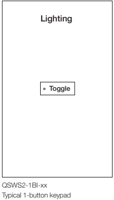
Animal Holding Room Control Narrative:
Diurnal cycle: At 7 AM set day / night variable to “day”, and at 7 PM set to “night”.
Manual control:
| Button | Button Engraving | Function | Day / Night Variable State | Scene Recalled | Purpose |
|
1 |
Toggle | Scene Toggle | Day | Bright White | Human Day Task Light |
| Dim White | Animal Day Normal Light | ||||
| Night | Red | Human Night Task Light | |||
| Off | Animal Night Normal Light |
Note: Advanced programming required to achieve 1-button keypad’s ability to recall different lighting states based on Day / Night State Variables
Automatic occupancy control
| System Input (Occupancy State) | Day/ Night Variable State | Scene Recalled (See Scene Table) |
| Occupied | Day | Unaffected |
| Unoccupied | Dim White | |
| Occupied | Night | Unaffected |
| Unoccupied | Off |
Scene Table
| Zones | ||
| Scenes | White Light Zone B | Red Light Zone B |
| Dimmed | Switched | |
| Off | 0 | Off |
| Bright White | 100 | Off |
| Dim White | 50 | Off |
| Red (Animal Dark) | Off | On |
| All Lights On (Test) | 100 | On |
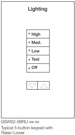
Procedure Room
Procedure Room Control Narrative:
Manual control
| Button | Button Engraving | Function | Scene Recalled | Purpose |
| 1 | High | Scene Select | High | General Lights: High Intensity |
| 2 | Medium | Scene Select | Medium | General Lights: Medium Intensity |
| 3 | Low | Scene Select | Low | General Lights: Low Intensity |
| 4 | Task | Toggle | Task On | Task Lights: On |
| Task Off | Task Lights: Off | |||
| 5 | Off | Scene Select | Off | All Lights: Off |
| Lower | Lower | General Lights: Lower Intensity | ||
| Raise | Raise | General Lights: Raise Intensity |
Automatic occupancy control
| System Input (Occupancy State) | Scene Recalled (See Scene Table) |
| Occupied | Unaffected |
| Unoccupied | Off |
Scene Table
| Scenes | Operating Area General Lighting | Operating Area Task Light |
| Zone A | Zone B | |
| High | 100% | Unaffected |
| Med | 60% | Unaffected |
| Low | 45% | Unaffected |
| Task On | Unaffected | On |
| Task Off | Unaffected | Off |
| Off | Off | Off |
| ▼ | Lower | Unaffected |
| ▲ | Raise | Unaffected |
System Commissioning Documentation
Commissioning Nomenclature
- Commissioning Milestones
Below are major project milestones that are essential to successful deployment of a Lutron system. Not all milestones are accomplished on-site. - Lutron Prewire Date(s)
An on-site visit designed to familiarize the electrical contractor with wiring and mounting of system devices, discuss the construction schedule, and review Lutron documentation. A Lutron field service engineer reviews the submittal package, particularly the oneline and the device specifications, and with the electrical contractor, answers questions regarding Lutron project submittals. - Lutron Commissioning Start
First day that Lutron service persons are on-site to begin commissioning the Lutron system. - All Lutron Devices Installed
Date when all Lutron devices are installed and energized according to instructions with all wiring terminations completed. - Lutron Server Commissioned
Lutron software installed and tested functional with connection to all processors. - Lutron Processors Network Configuration Complete
All Lutron supplied devices have been configured with IPv4 information provided by a network admin. Devices are on their permanent network and can correctly communicate with the server. - Lutron Commissioning Complete
All Lutron on-site commissioning activities, with the exception of training and acceptance
walk-throughs if applicable, have been completed. - Third-Party Acceptance Walkthrough Complete
Many projects hire third-party testing agencies to validate that systems operate as they were designed / intended to. This is the date that Lutron walked the system with the third-party representative to discuss system operation. - Customer Training Complete
This is the date that Lutron provided the end user, research staff, and / or facility team a full training on system operation and maintenance. - System Turned Over
Lutron has completed all startup activities and the system is under control of the site’s staff. Lutron is not expected back on-site, unless otherwise scheduled. - BACnet Enabled on Required Processors
All Lutron equipment has had its BACnet settings configured in accordance with design documents. - BACnet Integration IDs Configured and Transmitted
Lutron has provided a list of “Integration IDs”, numbers, and corresponding functions, to the appropriate parties. - BACnet Connection and Control Established by Others
The BACnet integrator has connected to and demonstrated an ability to control the Lutron system.
Commissioning Checklist
| Milestone | Commissioning Technician | Date |
| Lutron | ||
| Lutron Prewire Date(s) | ||
| Lutron Commissioning Started | ||
| All Lutron Devices Installed | ||
| Lutron Server Commissioned | ||
| Lutron Processors Network Configuration Complete | ||
| Lutron Commissioning Completed | ||
| Lutron On-site Testing Completed | ||
| Third-Party Acceptance Walkthrough Completed | ||
| Customer Training and Demonstration Completed | ||
| System Turned Over | ||
| BACnet Integration (Optional) | ||
| BACnet Enabled on Required Processors | ||
| BACnet Integration IDs Configured and Transmitted | ||
| BACnet Connection and Control Established by Others | ||
Processor Network Configuration Verification
| Processor Room Number | IP Address | Subnet Mask | Gateway | Lutron Configuration Completed By (Date) |
| Example: Room 101 | 10 121 233 2 | 255 255 255 252 | 10 121 233 1 | T Claudius (07/26/2021) |
Processor Network Configuration Documentation
This is where network configuration information of Lutron processors is recorded This information is provided by network admins that are controlling the network on which the vivarium system is operating
Room Commissioning Verification
| Room Number (Room Type) | Lutron Controlled Lighting Verified By (Date) | Room Functionally Tested By (Date) | Lutron Commissioning Completed (Date) |
| Example: Room 101 (Animal Holding) | A Tiberius (07/14/2021) | C Gaius (05/05/2021) | C Christofilakes (04/15/2022) |
Lutron Controlled Lighting Verification
Lutron services personnel will test all lighting zones connected to Lutron control devices to confirm they function as expected. These tests do not measure dimming performance or any other light quality factors.
Functional Test
A programmer qualified on the Lutron system specified will verify that programming of rooms matches approved submittals.
Animal Holding Room Testing Plan | Room Number
| Day / Night Variable | Trigger | Expected Output | Results Pass / Fail (Technician / Date) |
| Night to Day Transition | Trigger from Vue [Web Based UX] | Day/Night Variable: Day Unoccupied Light Level: Dim White [Scene] Applied: At Time of Event | |
|
Day | Toggle On [Keypad] | Bright White [Scene] | |
| Toggle Off [Keypad] | Dim White [Scene] | ||
| Occupied | Unaffected | ||
| Unoccupied | Dim White [Scene] | ||
| Day to Night Transition | Trigger from Vue [Web Based UX] | Day / Night Variable: Night Unoccupied Light Level: Off [Scene] Applied: At Time of Event | |
|
Night | Toggle On [Keypad] | Red (Animal Dark) [Scene] | |
| Toggle Off [Keypad] | Off [Scene] | ||
| Occupied | Unaffected | ||
| Unoccupied | Off [Scene] |


