URC LT-3100 Z-Wave Smart Dimmer
Thank you for purchasing the URC LT-3100 Dimmer!
This quick setup manual will help you plan and install your Z-Wave™ lighting solution. This product can be operated in any Z-Wave network with other Z-Wave certified devices from other manufacturers. All mains operated nodes within the network will act as repeaters regardless of vendor to increase reliability of the network.
Specifications
Power:
120V AC / 60Hz
Signal (Frequency):
908.42 MHz
Operating Temperature Range:
32-104 °F (0-40 °C)
Maximum Load:
400W Incandescent / 300W LED / 150 CFL (1-Gang), 300W Incandescent / 200W LED / 150 CFL (2-Gang) or 200W Incandescent / 150W LED / 100W CFL (3-Gang)
Approval:
UL Listed / FCC / IC / Z-Wave Plus™
Certified / CAN ICES-003 (B) / MB-003(B)
For indoor use. Specifications subject to change without notice due to continuing product improvement.
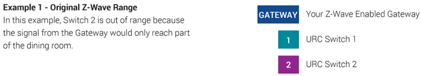
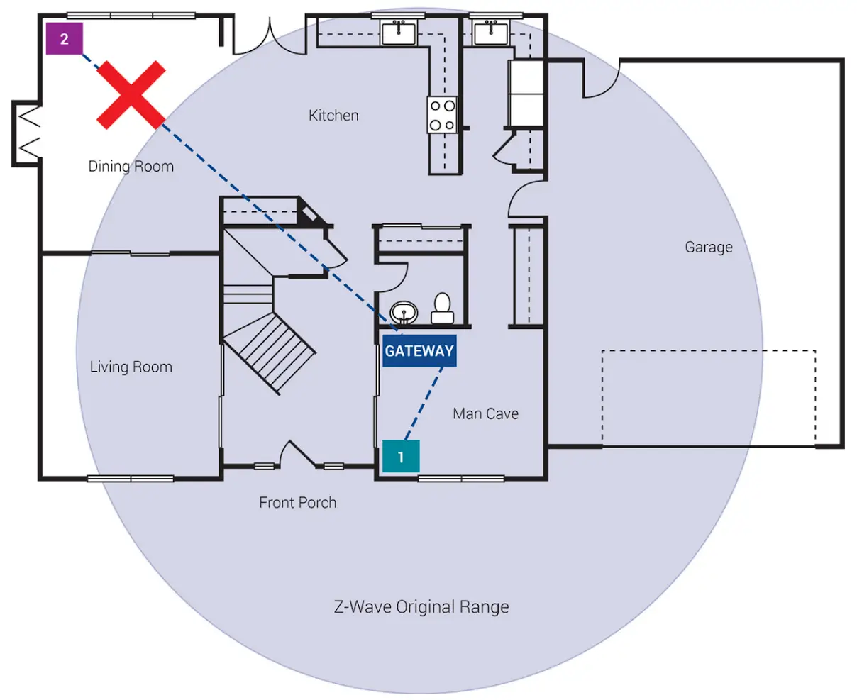
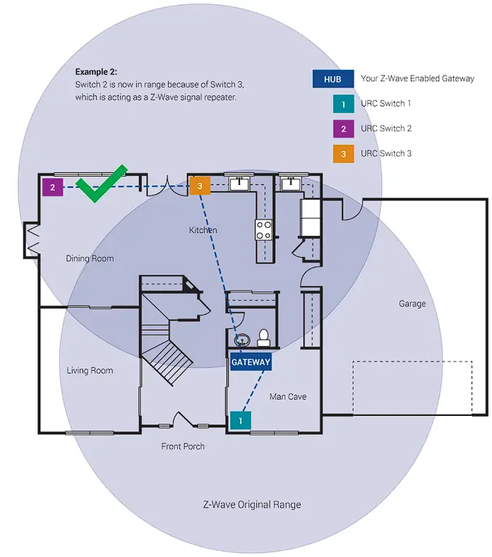
Z-Wave Network
Z-Wave can be used with a few devices or it can be used to build a large network. Below you’ll see two examples. In the first example, a user has a Gateway which is looking for Z-Wave devices within its radius. Z-Wave devices outside this radius will not be found and need to either be moved within the radius or use a repeating device to reach it. The second example shows how a repeater can be used to reach a device outside of the initial radius. Keep this in mind when building your own network and make sure to use the range estimator below.
| Material | Thickness | Signal Depreciation |
| Aerated Concrete Stone | < 30cm //11.8” | 20% |
| Aluminum Coating | < 1mm // 0.04” | 100% |
| Ceiling | < 30cm // 11.8” | 70% |
| Furniture [Non-wood] | < 30cm // 11.8” | 40-60% |
| Glass [No Metal Coating] | < 5cm // 2.0” | 10% |
| Inner Wall | < 30cm // 11.8” | 40% |
| Iron Reinforced Concrete | < 30cm // 11.8” | 30-90% |
| Metal Grid | < 1mm // 0.04” | 90% |
| Outer Wall | < 30cm // 11.8” | 60% |
| Plaster | < 10cm // 3.9” | 10% |
| Pumice | < 30cm // 11.8” | 10% |
| Red Brick | < 30cm // 11.8” | 35% |
| Stone | < 30cm // 11.8” | 30% |
NOTE: Z-Wave range will never be a perfect circle due to walls, furniture, etc. The above is for reference only.
Wiring Instructions
Please do not try installing this device if you are unsure of how electrical circuits operate within your home.
Technology upgrades can be exciting, but they can also be dangerous when not installed correctly.
|
| This device is intended for installation in accordance with the National Electric Code and local regulations in the United States, or the Canadian Electrical Code and local regulations in Canada. |
|
| Risk of Fire Risk of Electrical Shock Risk of Burns |
|
| TURN OFF THE POWER to the circuit for the dimmer and lighting fixture at the circuit breaker prior to installation. Wiring live connections can and will result in injury while also damaging the device. |
|
| This dimmer is designed for use only with permanently installed fixtures. To install multiple dimmers, remove the tabs as needed. Tabs 1-6 NOT REMOVED = 400W Tabs 1-3 REMOVED = 300W Tabs 4-6 REMOVED = 300W Tabs 1-6 REMOVED = 200W |
|
| To reduce the risk of overheating and possible damage to equipment, DO NOT attempt to control a receptacle, motor driven device, a fluorescent light fixture, or an appliance. |
|
| Please DO NOT use this dimmer to control Medical or Life Support equipment. |
|
| The metal plates surrounding the dimmer assembly are a heat sink. Max load rating of 400W is applicable when installed in a single gang-box with all six (6) tabs still intact. |
PLEASE NOTE: URC is unable to provide electrical and/or wiring advice outside of this document. If you are unable or unsure, please contact an electrician.
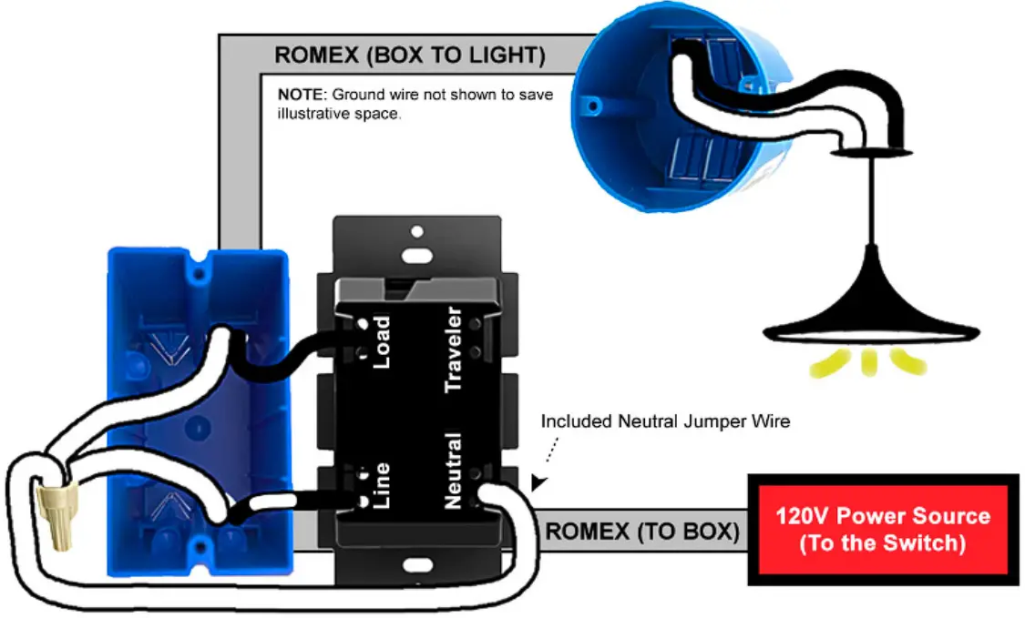
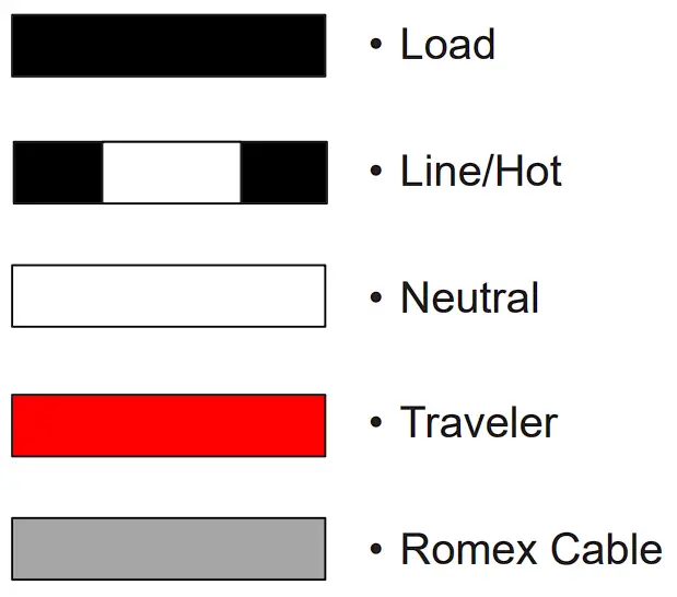
Wiring Instructions: Neutral Installation
Please use this if you have a neutral wire, typically white, in the installation area. For non-neutral installations or wiring configurations that use Traveler terminals of the LT-3100, more wiring diagrams and information are available within the product manual found at: https://urcportal.com/resources-total-control/
Single-Pole Installation (Single Dimmer)
3-Way Installation (Line/Load in Separate Boxes)
- The LT-3100 can be used in a 3-way/4-way lighting installation.
- The Master Load Controller must be defined in URC software.
- Secondary controllers must be defined in URC software.
- Multi-Way will not work without prior programming.
- Traveler Wire is not needed for Multi-Way configurations of two or more LT-3100s.
|
| Use two or more LT-3100s for the best possible user experience. |
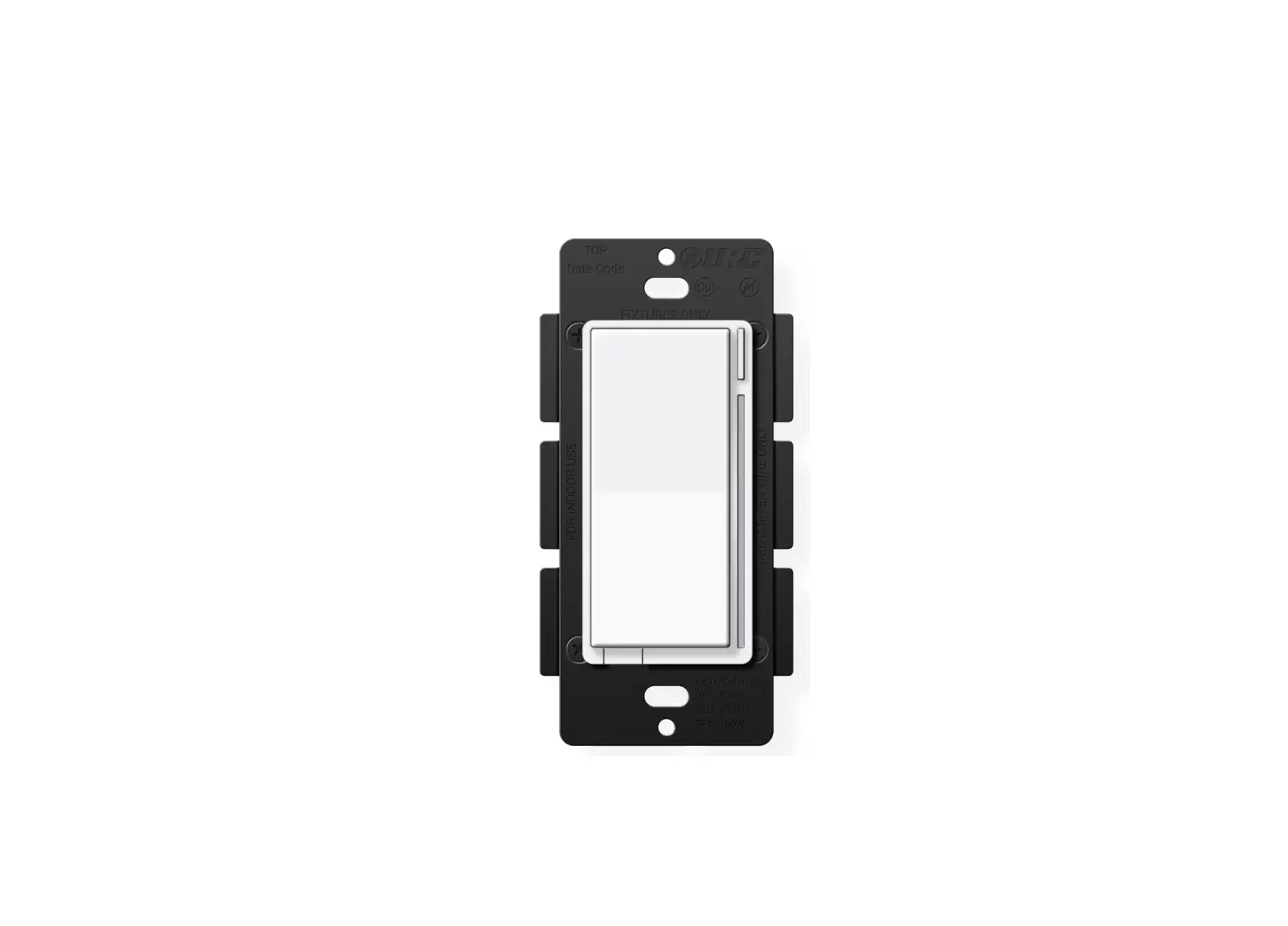
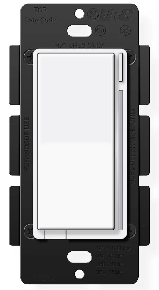
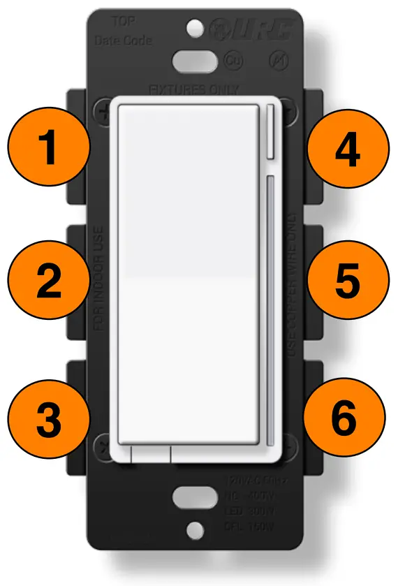
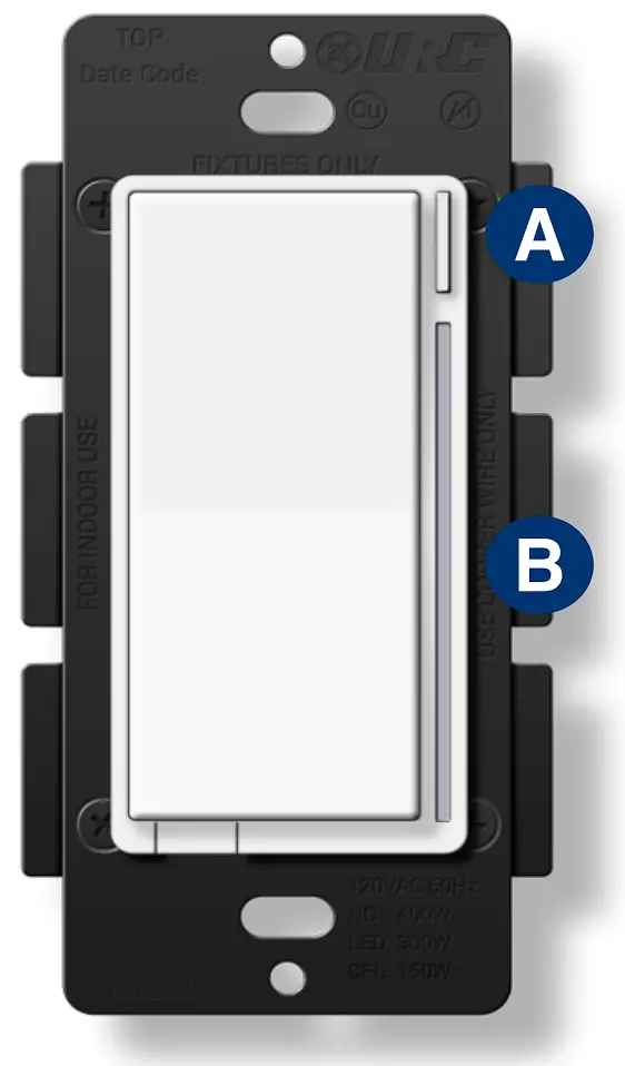
Product Description
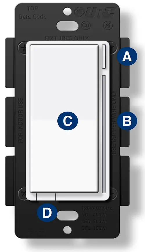
A. Config Button: This button is used to enter the configuration menu on your dimmer. When you hold it down for 10-15 seconds, the LED Bar (B) will light up Yellow to indicate you are in config mode. It can also be used to trigger a favorite scene. After setting up the scene, tap the button one time to trigger it.
B. RGB LED Notification Bar: This LED bar serves as a visual display for the dimness level of your lights as well as offering visual notifications based on events that are setup via the Gateway. It can be further configured, disabling or setting certain brightness levels.
C. Responsive Paddle: The paddle works in a similar manner to a standard dimmer. When you hold either up or down, the light dimmer will brighten or dim the lights to the preferred level. Tapping up will set the light to the last dim level. Tapping down will shut off the light.
The paddle may also be used for scene control. After creating the scenes, the paddle can be tapped up or down 1-5 times to trigger a scene.
D. Air Gap Dimmer: This will cut the power to the load your dimmer is wired to.
Including A Dimmer
Below are the steps for including (pairing) a dimmer to a Gateway.
Plan, Prep, and Install:
- Locate an area to install the dimmer that is within a recommend distance from the Gateway.
- Walls, ceilings, and even furniture may degrade communication between devices.
- Remember to turn off the power prior to installation.
- Check the signal range by holding the config button for 5-10 seconds.
[ Green = Good Signal / Red = Poor Signal ]
Including to the Network:
- Put the Gateway into inclusion mode.
- Once started, press the config button on the dimmer three times and the LED Bar will flash blue. If included successfully, the bar will turn green. If it turns red, the inclusion process failed.
Dimmer Not Including? Try an Exclusion:
- Put the Gateway into exclusion mode.
- Once started, press the config button on the dimmer three times. The LED Bar will turn Green if excluded successfully.
Dimmer Configuration Settings
There are a couple of ways to configure a dimmer. The first is via the dimmer itself, while the second is via the programming software.
| Parameter # | # Of Config Button Presses | About | Description |
| 1 | 1 | Dimming Speed | How fast or slow the light turns on. |
| 5 | 2 | Minimum Dim Level | Minimum level the light will dim to. |
| 6 | 3 | Maximum Dim Level | Maximum level the light will dim to. |
| 7 | 4 | Invert Dimmer | Inverts the dimmer. |
| 9 | 5 | Default Level (Local) | Dimmer default dim level when pressed locally. |
| 10 | 6 | Default Level (Z-Wave) | Dimmer default dim level when powered on via Z-Wave command. |
| 11 | 7 | Power On State | Which state the dimmer reverts to when power is restored. |
| 13 | 8 | LED Indicator Color | Default color of the LED Bar. |
| 14 | 9 | LED Indicator Intensity | Intensity level of the LED Bar. |
| 15 | 10 | LED Indicator Intensity (When Off) | Intensity level when the dimmer is off. |
| 17 | 11 | LED Indicator Timeout | Amount of time dim level is shown when the LED Bar is disabled. |
| 21 | 12 | AC Power Type | Set the power type the dimmer is using. |
| 22 | 13 | Dimmer Type | Set dimmer installation type. |
Configuration Logic
To enter configuration mode, hold down the Config Button (A) for 10-15 seconds and the LED Bar (B) will light up yellow.
Once your parameter has been selected,the LEDBar (B) will blink yellow. Now press up or down on the paddle to adjustthe parameter settings to yourliking.
Finally, once you’ve settled on a customization, it’s time to save the configuration settings.Hold the Config Button (A) for 10 seconds and the LED Bar (B) will then blink to confirm the settings were saved.
Security 2 DSK
The DSK can be found on the front of the switch (metal plate) and inside the box.
| Parameter # | Change at the Dimmer? | About | Description | Range | Default | Size (Bytes) |
| 1 | Yes | Dimming Speed | How fast or slow the light turns on when you hold the dimmer. (0 – Instant On) | 0-100s | 3s | 1 |
| 2 | No | Dimming Speed (from Dimmer) | How fast or slow the light turns dim when you adjust the dimmer remotely. (0 – Instant On | 101 – Sync w/ Param 1) | 0-101 | 101 | 1 |
| 3 | No | Ramp Rate | How fast or slow the light turns on when you press the dimmer 1x to bring from On to Off or Off to On. | 0-101 | 101 | 1 |
| 4 | No | Ramp Rate (from Dimmer) | How fast or slow the light turns on when you bring your dimmer from On to Off or Off to On remotely. | 0-101 | 101 | 1 |
| 5 | Yes | Minimum Dim Level | Minimum level the light dimmer will dim to. | 1-45% | 1% | 1 |
| 6 | Yes | Maximum Dim Level | Maximum level the light dimmer will dim to. | 55-99% | 99% | 1 |
| 7 | Yes | Invert Dimmer | Inverts the dimmer. | 0-1 | 0 (Disabled) | 1 |
| 8 | No | Auto Off Timer | Automatically turns the dimmer off after X amount of seconds. | 0-32767s | 0 (Off) | 2 |
| 9 | Yes | Default Level (Local) | Default Dim level for the dimmer when pressed locally. | 0-99% | 0 (Previous) | 1 |
| 10 | Yes | Default Level (Z-Wave) | Default Dim level for the dimmer when powered on via Z-Wave. | 0-99% | 0 (Previous) | 1 |
| 11 | Yes | Power On State | When power is restored, the dimmer reverts to either On, Off, or Last Level. | 0-99, 101 | 0 (Off) | 1 |
| 12 | Yes | Association Behavior | When should the switch send commands to associated devices [01 = Local / 02 = 3-Way / 03 = 3-Way & Local / 04 = Z-Wave Hub / 05 = Z-Wave Hub & Local / 06 = Z-Wave Hub & 3-Way / 07 = Z-Wave Hub & Local & 3-Way / 08 = Timer / 09 = Timer & Local / 10 = Timer & 3-Way / 11 = Timer & 3-Way & Local / 12= Timer & Z-Wave Hub / 13 = Timer & Z-Wave Hub & Local / 14 = Timer & Z-Wave Hub & 3 -Way / 15 = Al | 01-15 | 15 | 1 |
| 13 | Yes | LED Indicator Color | This will set the default color of the LED bar. | 0-255 | 170 (Blue) | 2 |
| 14 | Yes | LED Indicator Intensity | This will set the intensity of the LED bar. (0 – Off | 1 – Low | 5 – Med | 10 – High) | 0-10 | 5 | 1 |
| 15 | Yes | LED Indicator Intensity (When Off) | This is the intensity of the LED bar when the dimmer is off. (0 – Off | 1 – Low | 5 – Med | 10 – High) | 0-10 | 1 | 1 |
| 16 | No | LED Strip Effect | This will allow you to add some effects to your LED bar. | Varies by Byte* | 0 | 4 |
| 17 | Yes | LED Indicator Timeout | Changes the amount of time the RGB bar shows the Dim level if the LED bar had been disabled. | 0-10s | 3 | 1 |
| 18 | No | Active Power Reports | The power level change that will result in a new power report being sent. (0 – Disabled | 10 – 10% of prev report) | 0-100% | 10 | 1 |
| 19 | No | Periodic Power & Energy Reports | Time periods between consecutive power and energy reports being sent | 0-32767s | 3600 | 2 |
| 20 | No | Energy Reports | The energy level change that will result in a new energy report being sent. (0 – Disabled | 10 – 10% of prev report) | 0-100% | 10 | 1 |
| 21 | Yes | AC Power Type | Select whether you are wiring with or without a neutral wire. | 0-1 | 1 (Neutral) | 1 |
| 22 | Yes | Dimmer Type | Select which type of dimmer is installed. | 0-2 | 0 | 1 |
| 50 | No | Delay Adjustment | Time adjustments for how quickly the Dimmer reacts to paddle presses. | 1-9ms | 7 | 1 |
| 51 | No | Instant On | There is a delay that allows for multi-tap scene control. (0 – No Delay | 1 – Delay) | 0-1 | 1 (Delay) | 1 |
| 52 | No | Smart Bulb Mode | Puts the dimmer into Smart Bulb mode, disabling local control. | 0-1 | 0 (Normal) | 1 |
Association Groups
| Grouping Identifier | Max Nodes | Send Commands |
| Group 1 | 0x05 | Central Scene Notification |
| Basic Report | ||
| Multilevel Report | ||
| Protection Report | ||
| Device Reset Locally | ||
| Meter Report | ||
| Group 2 | 0x05 | Basic Set |
| Group 3 | 0x05 | Dimmer Multilevel Set |
| Group 4 | 0x05 | Dimmer Multilevel Set |
Group 1: Lifeline
Members of this group will receive unsolicited messages related to the status of the dimmer.
Group 2: Basic Setup
Sends start and stop level change to associated devices.
Group 3: Dimmer Multilevel Set
Sends dim/brighten commands to associated devices when the dimmer is pressed. This group can be used to keep the dimmers in sync.
Group 4: Dimmer Multilevel Set [Auxiliary Dimmer]
Sends start and stop level change to associated devices. This group allows an accessory dimmer to control multiple bulbs and/or dimmers.
Factory Default
You may factory reset the switch by holding down the Config Button for twenty (20) or more seconds. The LED Bar will turn Red and blink three (3) times to confirm. However, we recommend using a certified Z-Wave controller to remove the device from your network for factory resetting the switch. Only use either of these procedures in the event that the network primary controller is missing or otherwise inoperable.
About | Description | Config Button | LED Effect | LED Color | Duration | |
| Press / Hold | # Press / Sec | |||||
| Clear Notifications | Clears the RGB Bar of any notifications. | Press | 2x | N/A | N/A | N/A |
| Inclusion / Exclusion | 3x Tap of Config Button (30s timeout) | Press | 3x | Pulse | Blue (Default) | See desc |
| Disable Internal Relay | Disables the internal relay. | Press | 8x | Fast Blink | Red | 3x Blink |
| Enable Internal Relay | Enables the internal relay. | Press | 8x | Fast Blink | Green | 3x Blink |
| Z-Wave Signal Test | Tests the signal strength of the dimmer. | Hold | 5-10s | Solid | Green | N/A |
| Parameter Configuration | Change the parameters from the dimmer. | Hold | 10-15s | Solid | Yellow | N/A |
| Factory Reset | Factory reset the dimmer. | Hold | 20s | Solid | Red | 3x Blink |
Z-Wave Command Classes
5E – COMMAND_CLASS_ZWAVEPLUS_INFO
26 – COMMAND_CLASS_DIMMER_MULTILEVEL
70 – COMMAND_CLASS_CONFIGURATION
85 – COMMAND_CLASS_ASSOCIATION
59 – COMMAND_CLASS_ASSOCIATION_GRP_INFO
55 – COMMAND_CLASS_TRANSPORT_SERVICE
86 – COMMAND_CLASS_VERSION
72 – COMMAND_CLASS_MANUFACTURER_SPECIFIC
5A – COMMAND_CLASS_DEVICE_RESET_LOCALLY
73 – COMMAND_CLASS_POWERLEVEL
98 – COMMAND_CLASS_SECURITY
9F – COMMAND_CLASS_SECURITY_2
5B – COMMAND_CLASS_CENTRAL_SCENE
6C – COMMAND_CLASS_SUPERVISION
32 – COMMAND_CLASS_METER
75 – COMMAND_CLASS_PROTECTION
22 – COMMAND_CLASS_APPLICATION_STATUS
7A – COMMAND_CLASS_FIRMWARE_UPDATE_MD
FCC Statement
This device complies with part 15 of the FCC Rules. Operation is subject to the following two conditions: (1) This device may not cause harmful interference, and (2) this device must accept any interference received, including interference that may cause undesired operation.
This equipment should be installed and operated with minimum distance of 20 cm between the radiator and your body.
NOTE: This equipment has been tested and found to comply with the limits for a Class B digital device, pursuant to part 15 of the FCC Rules.
These limits are designed to provide reasonable protection against harmful interference in a residential installation. This equipment generates, uses and can radiate radio frequency energy and, if not installed and used in accordance with the instructions, may cause harmful interference to radio communications. However, there is no guarantee that interference will not occur in a particular installation. If this equipment does cause harmful interference to radio or television reception, which can be determined by turning the equipment off and on, the user is encouraged to try to correct the interference by one or more of the following measures.
- Reorient or relocate the receiving antenna.
- Increase the separation between the equipment and receiver.
- Connect the equipment into an outlet on a circuit different from that to which the receiver is connected.
- Consult the dealer or an experienced radio/TV technician for help.
MODIFICATION: Any changes or modifications not expressly approved by the grantee of this device could void the user’s authority to operate the device.
IC Statement
This device contains licence-exempt transmitter(s)/receiver(s) that comply with Innovation, Science and Economic Development Canada’s licenceexempt RSS(s). Operation is subject to the following two conditions:
- This device may not cause interference.
- This device must accept any interference, including interference that may cause undesired operation of the device.
This equipment complies with IC radiation exposure limits set forth for an uncontrolled environment. This equipment should be installed and operated with minimum distance of 20 cm between the radiator and your body.
Warranty
Universal Remote Control, Inc. (“URC”) warrants that the URC equipment shall be free from defects in material and workmanship under normal usage for one (1) year from purchase for all products with the exception of all Total Control® whole-house products which is for two (2) years from purchase, when such is purchased from URC. This limited warranty is valid only in the United States of America. URC warrants that the software will substantially conform in any material respect to its functional specifications at the time of delivery. URC shall not be liable for operational, technical or editorial errors and/or omissions made in the URC documentation. URC does not warrant that the URC software is bug-free or error free or that there are no errors/bugs in the URC software.URC equipment purchased from other than an authorized URC dealer or distributor are without warranty.In the event of any warranty claim, URC will, at its sole option, repair the URC equipment using new or comparable rebuilt parts, or exchange the URC equipment for new or rebuilt equipment. In the event of a defect, these are the end user’s exclusive remedies. All the URC equipment returned for service, exchange or repair require an RGA number. To obtain an RGA number, you must complete a Return Request Form which you may obtain by calling (914) 835-4484 or contacting URC at [email protected]. To obtain warranty service, end user must deliver the URC equipment, freight prepaid, in its original packaging or packaging affording adequate protection to URC at 37 Ramland Road, Unit 104, Orangeburg, NY 10962. It is end user’s responsibility to backup any macro programming, artwork, software or other materials that may have been programmed into the unit. It is likely that such data, software, or other materials will be lost during service and URC will not be responsible for any such damage or loss. A dated purchase receipt, bill of sale, installation contract or other verifiable proof of purchase is required.For detailed information regarding warranties and returns, please visit URC’s website available at http://www.urc-automation.com/warranty or call the Customer Service Center at (914) 835-4484.


 Manual")


