Seagate Barracuda ST2000LM015 2.5″ Internal Hard Drive
Introduction
This manual describes the functional, mechanical, and interface specifications for the following Seagate BarraCuda model drives:
| Standard models |
| ST2000LM015 |
| ST1000LM048 |
| ST500LM030 |
- These drives provide the following key features:
- 1000 Gs of non-operating shock and 400 Gs of operating shock.
- 128MB buffer.
- 5400-RPM spindle speed.
- Full-track multiple-sector transfer capability without local processor intervention.
- High instantaneous (burst) data-transfer rates (up to 6Gb/s).
- MTC TechnologyTM, proprietary data flow management
- Native Command Queuing (NCQ) with command ordering.
- Perpendicular recording technology.
- Quiet operation. Fluid Dynamic Bearing (FDB) motor.
- SeaToolsTM diagnostic software performs a drive self-test that eliminates unnecessary drive returns.
- State-of-the-art cache and on-the-fly error correction algorithms.
- Support for Read Multiple and Write Multiple commands.
- Support for S.M.A.R.T. drives monitoring and reporting.
- Worldwide Name (WWN) capability uniquely identifies the drive.
About the Serial ATA Interface
The Serial ATA interface provides several advantages over the traditional (parallel) ATA interface.
The primary advantages include the following:
- Easy installation and configuration with proper plug-and-play connectivity. It is not necessary to set any jumpers or other configuration options.
- Thinner and more flexible cabling for improved enclosure airflow and ease of installation.
- Scalability to higher performance levels.
In addition, Serial ATA makes the transition from parallel ATA easy by providing legacy software support. Serial ATA was designed to allow users to
install a Serial ATA host adapter and Serial ATA disk drive in the current system and expect all of the existing applications to work as normal. The Serial ATA interface connects each disk drive in a point-to-point configuration with the Serial ATA host adapter. There is no master/slave relationship with Serial ATA devices like there is with parallel ATA. If two drives are attached to one Serial ATA host adapter, the host operating system views the two devices as if they were both “masters” on two separate ports. This essentially means both drives behave as if they are Device 0 (master) devices.
Note
The host adapter may, optionally, emulate a master/slave environment to host software where two devices on separate Serial ATA ports are represented to host software as Device 0 (master) and Device 1 (slave) accessed at the same set of host bus addresses. A host adapter that emulates a master/slave environment manages two sets of shadow registers. This is not a typical Serial ATA environment.
The Serial ATA host adapter and drive share the function of emulating parallel ATA device behavior to provide backward compatibility with existing host systems and software. The Command and Control Block registers, PIO and DMA data transfers reset, and interrupts are all emulated.
The Serial ATA host adapter contains a set of registers that shadow the contents of the traditional device registers, referred to as the Shadow Register Block. All Serial ATA devices behave like Device 0 devices. For additional information about how Serial ATA emulates parallel ATA, refer to the Serial ATA International Organization: Serial ATA (Revision 3.2). The specification can be downloaded from www.serialata.org.
Drive Specifications
Unless otherwise noted, all specifications are measured under ambient conditions, at 25°C, and nominal power. For convenience, the phrases the
drive and this drive are used throughout this manual to indicate the following drive models:
The specification summaries listed in the following tables are for quick reference. For details on specification measurement or definition, refer to the
appropriate section of this manual.
Table 1: Drive Specifications Summary
| Drive Specification | ST2000LM015 | ST1000LM048 | ST500LM030 |
| Formatted capacity (1) | 2TB | 1TB | 500GB |
| Guaranteed sectors | 3,907,029,168 | 1,953,525,168 | 976,773,168 |
| Heads | 4 | 2 | |
| Disks | 2 | 1 | |
| Bytes per sector | 512 (logical) / 4096 (physical) | ||
| Recording density | 2276 Kb/in | ||
| Track density | 580 Ktracks/in avg | ||
| Areal density | 1320 Gb/in2 avg | ||
| Spindle speed | 5400 RPM | ||
| Maximum sustained data rate, OD read | 140 MB/s | ||
| Interface | SATA 6Gb/s | ||
|
ATA data-transfer modes supported | PIO modes 0–4 Multiword DMA modes 0–2
Ultra DMA modes 0–6 | ||
| Cache buffer | 128 MB | ||
| Height (mm/in) | 7.0 (± 0.2) / 0.276 (± 008) | ||
| Width (mm/in) | 69.85 (± 0.25) / 2.750 (± 0.010) | ||
| Length (mm/in) | 100.35 (+0.20/-0.25) / 3.951 (+0.008/-0.010) | ||
| Weight (g/lb) max | 90 / 0.198 | 85 / 0.187 | |
| Average latency | 5.6 ms | ||
| Startup current, Max (+5V) | 1.0 A | ||
| Voltage tolerance (including noise) | 5V ± 5% | ||
| Non-Operating (Ambient °C) | –40° to 70° | ||
| Operating ambient temperature (min °C) | 0° | ||
| Operating temperature (drive case max °C) | 60° † | ||
| Temperature gradient | 20°C per hour max (operating) 35°C per hour max (non-operating) | ||
| Relative humidity | 5% to 95% (operating)
5% to 95% (non-operating) | ||
| Relative humidity gradient (max) | 30% per hour | ||
| Wet bulb temperature | 37.7°C max (operating) 40.0°C max (non-operating) | ||
| Altitude, operating | –304.8 m to 3048 m (–1000 ft to 10,000+ ft) | ||
| Altitude, non-operating (below mean sea level, max) | –304.8 m to 12,192 m (–1000 ft to 40,000+ ft) | ||
| Drive Specification | ST2000LM015 | ST1000LM048 | ST500LM030 |
| Operational Shock | 400 Gs at 2 ms max | ||
| Non-Operational Shock | 1000 Gs at 1 ms max | ||
| Vibration, operating | 5–200 Hz: 2.0 Gs
201–500 Hz: 1.0 Gs | ||
| Vibration, non-operating | 5–500 Hz: 5.0 Gs | ||
| Non-recoverable read errors | 1 per 1014 bits read | ||
|
Rated workload | Average annualized workload rating: <55 TB/year.
The AFR specification for the product assumes the I/O workload does not exceed the aver- age annualized workload rate limit of 55 TB/year. Workloads exceeding the annualized rate may degrade the product AFR and impact reliability as experienced by the particular appli- cation. The average annualized workload rate limit is in units of TB per calendar year. | ||
|
Warranty | To determine the warranty for a specific drive, use a web browser to access the following web page: http://www.seagate.com/support/warranty-and-replacements/.
From this page, click on the “Is my Drive under Warranty” link. The following are required to be provided: the drive serial number, model number (or part number) and country of purchase. The system will display the warranty information for the drive. | ||
| Load-unload cycles | 600,000 at 25°C, 50% rel. humidity | ||
| Supports Hotplug operation per the Serial ATA Revision 3.2 specification | Yes | ||
One GB equals one billion bytes when referring to hard drive capacity. Accessible capacity may vary depending on the operating environment and formatting.
Seagate does not recommend operating at sustained case temperatures above 60°C. Operating at higher temperatures will reduce the useful life of the product.
Formatted Capacity
| Model | Formatted Capacity(1) | Guaranteed Sectors | Bytes per Sector |
| 2TB model | 2000 GB | 3,907,029,168 |
512 (logical) / 4096 (physical) |
| 1TB model | 1000 GB | 1,953,525,168 | |
| 500GB model | 500 GB | 976,773,168 |
One GB equals one billion bytes when referring to hard drive capacity. Accessible capacity may vary depending on the operating environment and formatting.
LBA mode
When addressing these drives in LBA mode, all blocks (sectors) are consecutively numbered from 0 to n–1, where n is the number of guaranteed
sectors as defined above.
Refer to Configuring and Mounting the Drive on page 18 (words 60-61 and 100-103) for additional information about 48-bit addressing support
of drives with capacities over 137 GB.
Physical organization
| Drive model | Read/write heads | Number of discs |
| ST2000LM015 | 4 | 2 |
| ST1000LM048 and ST500LM030 | 2 | 1 |
Recording and Interface Technology
| Interface | SATA 6Gb/s |
| Recording method | Perpendicular |
| Recording density | 2276 Kb/in |
| Track density | 580 ktracks/in avg |
| Areal density | 1320 Gb/in2 avg |
| Spindle speed | 5400 RPM |
| Data transfer rate (up to) | 140 MB/s |
Physical Characteristics
| Height (mm/in) | 7.0 (± 0.2) / 0.276 (± 008) |
| Width (mm/in) | 69.85 (± 0.25) / 2.750 (± 0.010) |
| Length (mm/in) | 100.35 (+0.20/-0.25) / 3.951 (+0.008/-0.010) |
| Typical weight (g/lb) | 90 / 0.198 (ST2000LM015)
85 / 0.187 (ST1000LM048 & ST500LM030) |
| Cache buffer | 128MB |
Seek time
Seek measurements are taken with nominal power at 25°C ambient temperature. All times are measured using drive diagnostics. The specifications in the table below are defined as follows:
- Track-to-track seeks time is an average of all possible single-track seeks in both directions.
- Average seek time is a true statistical random average of at least 5000 measurements of seeks between random tracks, with less overhead.
Table 2 Typical seek times
| Typical seek times (ms) | Read |
| Track-to-track | 1.5 |
| Average | 13.0 |
| Average latency | 5.6 |
Note
These drives are designed to consistently meet the seek times represented in this manual. Physical seeks, regardless of mode (such as track-to-track and average), are expected to meet the noted values. However, due to the manner in which these drives are formatted, benchmark tests that include command overhead or measure logical seeks may produce results that vary from these specifications.
Start/stop times
Table 3 Start/stop times
| Capacity | 1-disk models | 2-disk models | 1-disk models | 2-disk models |
| Typical seek times (ms) | Typical | Max @ 25°C | ||
| Power-on to ready (sec) | 2.8 | 3.3 | 3.0 | 3.5 |
| Standby to ready (sec) | 2.5 | 3.0 | ||
Power Specifications
The drive receives DC power (+5V) through a native SATA power connector (refer to Figure 3).
Power consumption
Power requirements for the drives are listed in the table in Table 4. Typical power measurements are based on an average of drives tested, under nominal conditions, at 25°C ambient temperature. These power measurements are done with Interface Power Management modes like HIP M and DIPM enabled.
- Spinup power
Spinup power is measured from the time of power-on to the time that the drive spindle reaches operating speed. - Seek mode
During seek mode, the read/write actuator arm moves toward a specific position on the disk surface and does not execute a read or write operation. Servo electronics are active. Seek mode power is measured based on three random seek operations every 100 ms. This model is not typical. - Read/write power and current
Read/write power is measured with the heads on track, based on three 63-sector read or write operations every 100 ms. - Idle mode power
Idle mode power is measured with the drive up to speed, with servo electronics active, and with the heads in a random track location. - Standby mode
During standby mode, the drive accepts commands, but the drive is not spinning, and the servo and read/write electronics are in power-down mode.
Table 4 DC Power Requirements
| Power Dissipation | 1-disk models
+5V input average (25° C) | 2-disk models
+5V input average (25° C) |
| Spinup (max) | 1.00A | |
| Write average | 1.70W | 1.80W |
| Read average | 1.60W | 1.70W |
| Idle, performance (1) | 1.40W | 1.50W |
| Idle, active | 0.69W | 0.85W |
| Idle, low power mode | 0.45W | 0.50W |
| Standby(2) | 0.13W | |
| Sleep | 0.13W | |
- During periods of drive idle, some offline activity may occur according to the S.M.A.R.T. specification, which may increase acoustic and power to operational levels.
- Standby power is measured at a steady state (after 200ms from transition)
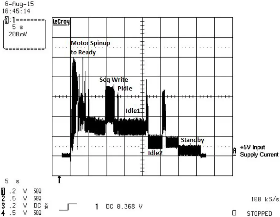
Typical current profiles
The typical 5V startup and operation current profile is shown in Figure 1 and Figure 2.
Figure 1 Typical 1D – 5V Startup and Operation Current Profile
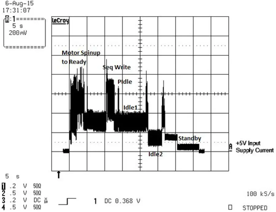 Figure 2 Typical 2D – 5V Startup and Operation Current Profile
Conducted noise
Input noise ripple is measured at the host system power supply across an equivalent 15-ohm resistive load on the +5 volt line.
- Using 5-volt power, the drive is expected to operate with a maximum of 100 mV peak-to-peak square-wave injected noise at up to 20 MHz.
Note: Equivalent resistance is calculated by dividing the nominal voltage by the typical RMS read/write current.
Supply Voltage
| Allowable voltage | 5V ± 5% |
| Allowable noise/ripple | 100 p-p max, 0-20 MHz |
| Allowable supply rise time | <100 ms |
Power management modes
The drive provides programmable power management to provide greater energy efficiency. In most systems, power management is controlled through the system setup program. The drive features the following power-management modes:
| Power modes | Heads | Spindle | Buffer |
| Active (operating) | Tracking | Rotating | Full power |
| Idle, performance | Tracking | Rotating | Self-refresh—low power |
| Idle, Active | Floating | Rotating | Self-refresh—low power |
| Idle, low power | Parked | Rotating | Self-refresh—low power |
| Standby | Parked | Stopped | Self-refresh—low power |
| Sleep | Parked | Stopped | Self-refresh—low power |
Active mode
The drive is in active mode during the read/write and seek operations.
Idle mode
The buffer remains enabled, and the drive accepts all commands and returns to active mode any time disk access is necessary.
Standby mode
The drive enters standby mode when the host sends a standby Immediate command. If the host has set the standby timer, the drive can also enter standby mode automatically after the drive has been inactive for a specific length of time. The standby timer delay is established using a standby or idle command. In standby mode, the drive buffer is enabled, the heads are parked and the spindle is at rest. The drive accepts all commands and returns to active mode any time disk access is necessary.
Sleep mode
The drive enters sleep mode after receiving a sleep command from the host. In sleep mode, the drive buffer is disabled, the heads are parked and the spindle is at rest. The drive leaves sleep mode after it receives a hard reset or soft reset from the host. After receiving a reset, the drive exits sleep mode and enters standby mode with all current translation parameters intact.
Idle and standby timers
Each time the drive performs an active function (read, write, or seek), the standby timer is reinitialized and begins counting down from its specified delay times to zero. If the standby timer reaches zero before any driving activity is required, the drive makes a transition to standby mode. In both Idle and standby modes, the drive accepts all commands and returns to active mode when disk access is necessary.
Environmental Specifications
This section provides the temperature, humidity, shock, and vibration specifications for BarraCuda drives. Ambient temperature is defined as the temperature of the environment immediately surrounding the drive. Above 1000 feet (305 meters), the maximum temperature is derated linearly by 1°C every 1000 feet.
Table 5: Environmental specifications
| Parameters | Operating | Non-Operating |
| Ambient temperature | 0° to 60°C (32° to 140°F) | -40° to 70°C (-40° to 158°F) |
| Temperature gradient | 20°C per hour (36°F per hour) max, without condensation | 35°C per hour (63°F per hour) max, without condensation |
| Humidity | 5% to 95% non-condensing
(30% per hour) | 5% to 95% non-condensing
(30% per hour) |
| Wet bulb | 37.7°C (99.8°F) max | 40°C (104°F) max |
| Altitude | -304.8m to 3048m
(-1000ft to 10,000ft) | -304.8m to 12,192m
(-1000ft to 40,000ft) |
- Note: Seagate does not recommend operating at sustained case temperatures above 60°C. Operating at higher temperatures will reduce the useful life of the product.
- Note: The recommended storage period:
- 1 year under controlled conditions of 34°C 90%RH or less
- 90 days in uncontrolled storage conditions
Shock
All shock specifications assume that the drive is mounted securely with the input shock applied at the drive mounting screws. Shock may b e applied in the X, Y, or Z axis.
Operating shock
These drives comply with the performance levels specified in this document when subjected to a maximum operating shock of 400 Gs based on half-sine shock pulses of 2ms. Shocks should not be repeated more than one time per axis.
Non-operating shock
The non-operating shock level that the driver can experience without incurring physical damage or degradation in performance when subsequently put into operation is 1000 Gs based on a nonrepetitive half-sine shock pulse of 1 ms duration.
Vibration
All vibration specifications assume that the drive is mounted securely with the input vibration applied at the drive mounting screws. Vibration may be applied in the X, Y, or Z axis.
Operating vibration
The maximum vibration levels that the drive may experience while meeting the performance standards specified in this document are specified below.
| 5–200 Hz | 2.0 Gs (0 to peak). Max displacement may apply below 10 Hz. |
| 201–500 Hz | 1.0 Gs (0 to peak). |
Non-operating vibration
The maximum non-operating vibration levels that the drive may experience without incurring physical damage or degradation in performance when subsequently put into operation are specified below.
5–500 Hz: 5.0 Gs (0 to peak). Max displacement may apply below 22 Hz.
Acoustics
Drive emission of sound is measured consistent with the ECMA-74 and its referenced standards. Testing is conducted at room temperatur e (approximately 25°C). Emission levels are reported as the total A-weighted sound power levers for steady state, idle, and active seeks modes of operation.
Table 6 Drive A-weighted Sound Power Levels (SWL, BA)
| 1-disk models | 2-disk models | |
| Idle(1) | 2.0 bels (typ)
2.2 bels (max) | 2.2 bels (typ)
2.4 bels (max) |
| Performance Seek | 2.2 bels (typ)
2.4 bels (max) | 2.4 bels (typ)
2.6 bels (max) |
- During periods of drive idle, some offline activity may occur according to the S.M.A.R.T. specification, which may increase acoustic and power to operational levels.
Test for prominent discrete tones (PDTs)
Seagate follows the ECMA-74 standards for the measurement and identification of PDTs. An exception to this process is the use of the absolute threshold of hearing. Seagate uses the lower limit for the threshold curve* to discern tone audibility and to compensate for the inaudible components of sound prior to the computation of tone ratios according to Annex D of the ECMA-74 standards.
*Defined as the median curve given by ISO 389-7 (Tf curve) minus 10dB at all frequencies.
Electromagnetic Immunity
When properly installed in a representative host system, the drive operates without errors or degradation in performance when subjected to the radio frequency (RF) environment as defined in Table 7.
Table 7 Radio Frequency Environments
| Test | Description | Performance Level | Reference Standard |
| Electrostatic discharge | Contact, HCP, VCP: ± 4 kV; Air: ± 8 kV | B | EN 61000-4-2: 95 |
| Radiated RF immunity | 80 to 1GHz, 3 V/m, 80% AM with 1 kHz sine
900 MHz, 3 V/m, 50% pulse modulation @ 200 Hz | A | EN 61000-4-3: 96
ENV 50204: 95 |
| Electrical fast transient | ± 1 kV on AC mains, ± 0.5 kV on external I/O | B | EN 61000-4-4: 95 |
| Surge immunity | ± 1 kV differential, ± 2 kV common, AC mains | B | EN 61000-4-5: 95 |
| Conducted RF immunity | 150 kHz to 80 MHz, 3 Vrms, 80% AM with 1 kHz sine | A | EN 61000-4-6: 97 |
| Power Frequency H-field immunity | 1 A/m, 50Hz/60Hz, 3 axes | A | EN 61000-4-8: 97 |
|
Voltage dips interrupts | 30% Reduction for 25 cycles
>95% Reduction for 250 cycles >95%, 0.5 cycles | C C B |
EN 61000-4-11: 94 |
DC Magnetic Field Immunity
Table 8: DC Magnetic Field Immunity
| Test | Product Spec (Standalone) |
| DC Magnetic Field Immunity 1, 2, 3 | 400 Gauss, RMS |
| 1 Field in Gauss at the drive envelope. Testing per procedures 20800109-349 and 20800109-350.
2 Passing Field in Gauss at the drive envelope. In practice, testing is conducted using a fixed distance from the bottom of the mag-net to the top of the drive. Calibration of the field vs. distance is done with a Hall probe with no magnetic materials present. 3 Testing to be done with magnet .375” dia. x 0.100” Ni-plated NdFeB; B,~11.5 kG, magnetized along its length; the magnet is oriented with the length perpendicular to the drive cover/PCBA. Drive to be properly secured during test. | |
Reliability
| Non-recoverable read errors | 1 per 1014 bits read, max |
| Load/Unload (U/UL)
25°C, 50% relative humidity |
600,000 software-controlled power on/off cycles 20,000 hard power on/off cycles |
| Rated workload | Average annualized workload rating: <55 TB/year.
The AFR specification for the product assumes the I/O workload does not exceed the average annualized workload rate limit of 55 TB/year. Workloads exceeding the annualized rate may degrade the product AFR and impact reliability as experienced by the particular application. The average annualized workload rate limit is in units of TB per calendar year. |
| Warranty | To determine the warranty for a specific drive, use a web browser to access the following web page: http://www.seagate.com/support/warranty-and-replacements/.
From this page, click on the “Is my Drive under Warranty” link. The following are required to be provided: the drive serial number, model number (or part number) and country of purchase. The system will dis- play the warranty information for the drive. |
Agency Certification
Safety certification
These products are certified to meet the requirements of UL60950-1, CSA60950-1, and EN60950 and so marked as to the certified agency.
The following regulatory model number represents all features and configurations within the series:
Regulatory Model Numbers: SDC001/SDC003
Electromagnetic Compatibility (EMC)
Hard drives that display the CE mark comply with the European Union (EU) requirements specified in the Electromagnetic Compatibility Directive 2004/108/EC (Until 19th April 2016) and 2014/30/EU (From 20th April 2016). Testing is performed to the levels specified by the product standards for Information Technology Equipment (ITE). Emission levels are defined by EN 55022, and Class B and immunity levels are defined by EN 55024.
Drives are tested in representative end-user systems. Although CE-marked Seagate drives comply with the directives when used in the test systems, we cannot guarantee that all systems will comply with the directives. The drive is designed for operation inside a properly designed enclosure, with properly shielded I/O cable (if necessary) and terminators on all unused I/O ports. Computer manufacturers and system integrators should confirm EMC compliance and provide CE marking for their products.
Korean RRA
If these drives have the Korean Communications Commission (KCC) logo, they comply with paragraph 1 of Article 11 of the Electromagnetic Compatibility Control Regulation and meet the Electromagnetic Compatibility (EMC) Framework requirements of the Radio Research Agency (RRA ) Communications Commission, Republic of Korea.
These drives have been tested and comply with the Electromagnetic Interference/Electromagnetic Susceptibility (EMI/EMS) for Class B products. Drives are tested in a representative, end-user system by a Korean-recognized lab.
Australian RCM Compliance Mark
Models displayed with the RCM compliance mark, comply with the mandatory standards as per the Australian Communications and Media Author-ity (ACMA) Electromagnetic Compatibility (EMC) regulatory arrangement.
FCC verification
These drives are intended to be contained solely within a personal computer or similar enclosure (not attached as an external device). As such, each drive is considered to be a subassembly even when it is individually marketed to the customer. As a subassembly, no Federal Communications Commission verification or certification of the device is required.
Seagate has tested this device in enclosures as described above to ensure that the total assembly (enclosure, disk drive, motherboard, power supply, etc.) does comply with the limits for a Class B computing device, pursuant to Subpart J, Part 15 of the FCC rules. Operation with noncertified assemblies is likely to result in interference to radio and television reception.
Radio and television interference. This equipment generates and uses radio frequency energy and if not installed and used in strict accordance with the manufacturer’s instructions, may cause interference to radio and television reception.
This equipment is designed to provide reasonable protection against such interference in a residential installation. However, there is no guarantee that interference will not occur in a particular installation. If this equipment does cause interference to radio or television, which can be determined by turning the equipment on and off, users are encouraged to try one or more of the following corrective measures:
- Reorient the receiving antenna.
- Move the device to one side or the other of the radio or TV.
- Move the device farther away from the radio or TV.
- Plug the computer into a different outlet so that the receiver and computer are on different branch outlets.
If necessary, users should consult the dealer or an experienced radio/television technician for additional suggestions. Users may find helpful th e following booklet prepared by the Federal Communications Commission: How to Identify and Resolve Radio-Television Interference Problems. Thi s booklet is available from the Superintendent of Documents, U.S. Government Printing Office, Washington, DC 20402. Refer to publication number 004-000-00345-4.
Environmental Protection
Seagate designs its products to meet environmental protection requirements worldwide, including regulations restricting certain chemical substances.
European Union Restriction of Hazardous Substances (RoHS) Directive
The European Union Restriction of Hazardous Substances (RoHS) Directive, restricts the presence of chemical substances, including Lead, Cadmium, Mercury, Hexavalent Chromium, PBB, and PBDE, in electronic products, effective July 2006. This drive is manufactured with components and materials that comply with the RoHS Directive.
China Requirements — China RoHS 2
China RoHS 2 refers to the Ministry of Industry and Information Technology Order No. 32, effective July 1, 2016, titled Management Methods for the Restriction of the Use of Hazardous Substances in Electrical and Electronic Products. To comply with China RoHS 2, we determined this product’s Environmental Protection Use Period (EPUP) to be 20 years in accordance with the Marking for the Restricted Use of Hazardous Substances in Electronic and Electrical Products, SJT 11364-2014.
(Management Methods for the Restriction of the Use of Hazardous Substances in Electrical and Electronic Products _ China RoHS)
(Name and Content of the Hazardous Substances in Product)
Table 9 Hazardous Substances
|
Part Name | Hazardous Substances | |||||
| Lead
(Pb) | Mercury
(Hg) | Cadmium
(Cd) | Hexavalent Chromium
(CF (VI)) | Polybrominated
biphenyls (PBB) | Polybrominated
diphenyl ethers (PBDE) | |
| PCBA | X | O | O | O | O | O |
| Chassis | X | O | O | O | O | O |
| SJ/T 11364
This table is prepared in accordance with the provisions of SJ/T 11364-2014 O: Indicates that the hazardous substance contained in all of the homogeneous materials for this part is below the limit requirement of GB/T26572. X: Indicates that the hazardous substance contained in at least one of the homogeneous materials used for this part is above the limit requirement of GB/T26572. | ||||||
Corrosive Environment
Seagate electronic drive components pass accelerated corrosion testing equivalent to 10 years of exposure to light industrial environments containing sulfurous gases, chlorine, and nitric oxide, classes G and H per ASTM B845. However, this accelerated testing cannot duplicate every potential application environment.
Users should use caution exposing any electronic components to uncontrolled chemical pollutants and corrosive chemicals as electronic drive component reliability can be affected by the installation environment. The silver, copper, nickel, and gold films used in Seagate products are especially sensitive to the presence of sulfide, chloride, and nitrate contaminants. Sulfur is found to be the most damaging. In addition, electronic components should never be exposed to condensing water on the surface of the printed circuit board assembly (PCBA) or exposed to an ambient relative humidity greater than 95%. Materials used in cabinet fabrication, such as vulcanized rubber, that can outgas corrosive compounds should be minimized or eliminated. The useful life of any electronic equipment may be extended by replacing materials near circuitry with sulfide-free alternatives.
Configuring and Mounting the Drive
This section contains the specifications and instructions for configuring and mounting the drive.
Handling and Static-Discharge Precautions
After unpacking, and before installation, the drive may be exposed to potential handling and electrostatic discharge (ESD) hazards. Observe the following standard handling and static-discharge precautions.
CAUTION
- Keep the drive in the electrostatic discharge (ESD) bag until ready for installation to limit the drive’s exposure to ESD.
- Before handling the drive, put on a grounded wrist strap, or ground yourself frequently by touching the metal chassis of a computer that is plugged into a grounded outlet. Wear a grounded wrist strap throughout the entire installation procedure.
- Handle the drive by its edges or frame only.
- The drive is extremely fragile—handle it with care. Do not press down on the drive top cover.
- Always rest the drive on a padded, antistatic surface until mounting it in the computer.
- Do not touch the connector pins or the printed circuit board.
- Do not remove the factory-installed labels from the drive or cover them with additional labels. Removal voids the warranty. Some factory-installed labels contain information needed to service the drive. Other labels are used to seal out dirt and contamination.
Configuring the Drive
Each drive on the Serial ATA interface connects in a point-to-point configuration with the Serial ATA host adapter. There is no master/slave relationship because each drive is considered a master in a point-to-point relationship. If two drives are attached to one Serial ATA host adapter, the host operating system views the two devices as if they were both “masters” on two separate ports. Both drives behave as if they are Device 0 (master) devices.
Serial ATA Cables and Connectors
The Serial ATA interface cable consists of four conductors in two differential pairs, plus three ground connections. The cable size may be 30 to 26 AWG with a maximum length of one meter (39.37 in). Refer to Table 10 for connector pin definitions. Either end of the SATA signal cable can be attached to the drive or host.
For direct backplane connection, the drive connectors are inserted directly into the host receptacle. The drive and the host receptacle incorporate features that enable the direct connection to be hot-pluggable and blind-mateable. For installations that require cables, users can connect the drive as shown in Figure 3.
Figure 3 Attaching SATA Cabling
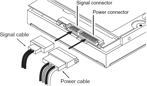
Each cable is keyed to ensure correct orientation. BarraCuda drives support latching SATA connectors.
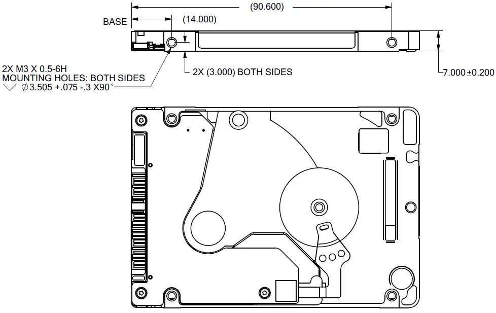
Drive Mounting
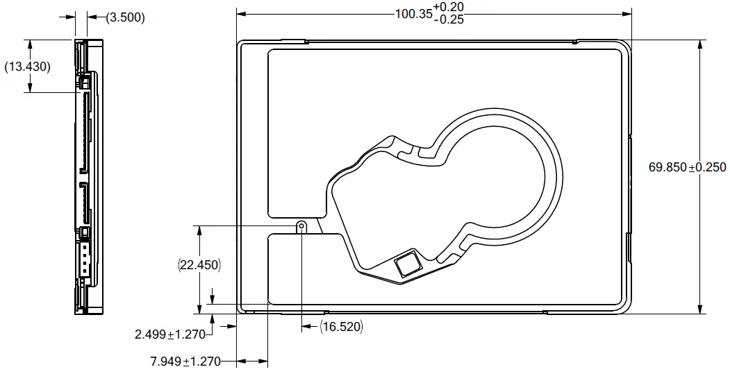
Users can mount the drive in any orientation using four screws in the side-mounting holes or four screws in the bottom-mounting holes. Refer to Figure 4 and Figure 5 for drive mounting dimensions. Follow these important mounting precautions when mounting the drive:
- Allow a minimum clearance of 0.030 in (0.76 mm) around the entire perimeter of the drive for cooling.
- Use only M3 x 0.5 mounting screws.
- Do not overtighten the mounting screws. Maximum torque: 4.0 in-lb (0.4519 N-m).
- Four (4) threads (0.080 in, 2.032 mm) minimum screw engagement recommended.
- Avoid excessive drive distortion when mounting. Refer to the following specifications for stiffness/deflection information:
| Top cover stiffness/deflection | |
| Operating: no performance degradation, emitted noise, mechanical damage, or hard errors | 10 mm probe: 2.0kgf (typical) |
| Non-operating: no hard errors | 10 mm probe: maximum 2.0kgf (instantaneous) |
Figure 4 Mounting Dimensions (for 1-disk models).
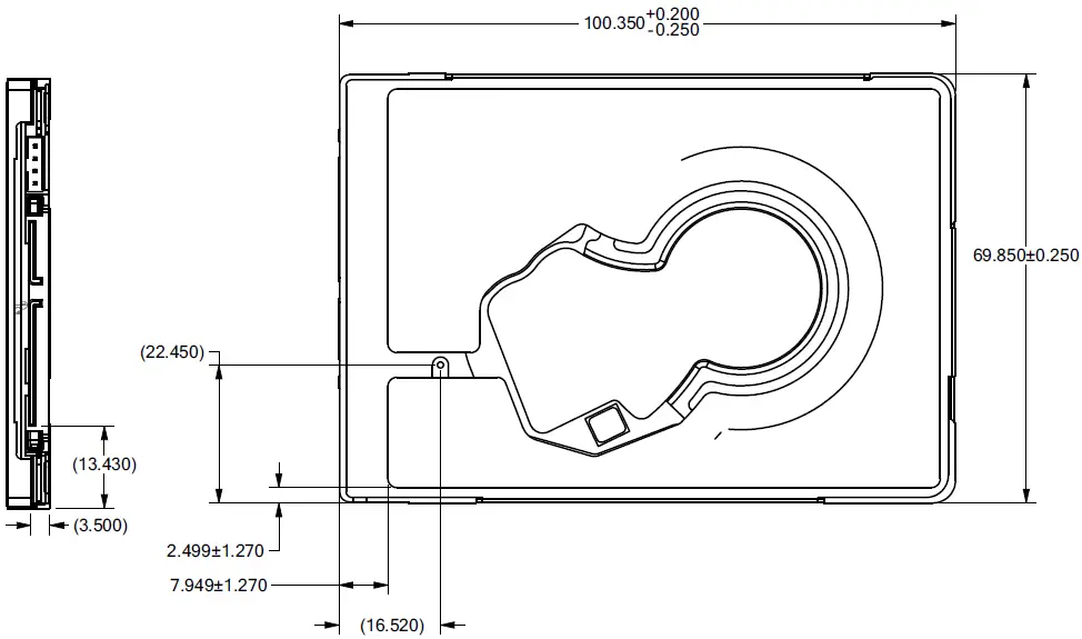
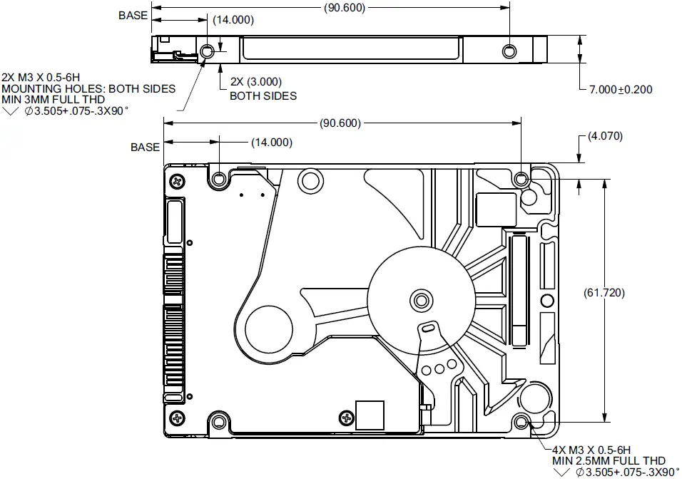 Figure 5 Mounting Dimensions (for 2-disk models)
Serial ATA (SATA) Interface
These drives use the industry-standard Serial ATA interface that supports FIS data transfers. It supports ATA programmed input/output (PIO) modes 0–4; multiword DMA modes 0–2, and Ultra DMA modes 0–6. The drive also supports the use of the IORDY signal to provide reliable high-speed data transfers.
For detailed information about the Serial ATA interface, refer to the Serial ATA: High Speed Serialized AT Attachment specification.
Hot-Plug Compatibility
BarraCuda drives incorporate connectors that enable users to hot plug these drives in accordance with the Serial ATA: High-Speed Serialized A T Attachment specification revision 2.0. This specification can be downloaded from www.serialata.org. This device requires a COMRESET from the host after a hotplug event.
Serial ATA Device Plug Connector Pin Definitions
Table 10 summarizes the signals on the Serial ATA interface and power connectors. Refer to the Notes below.
Table 10 Serial ATA Connector Pin Definitions
| Segment | Pin | Function | Definition |
|
Signal | S1 | Ground | 2nd mate |
| S2 | A+ | Differential signal pair A from Phy | |
| S3 | A- | ||
| S4 | Ground | 2nd mate | |
| S5 | B- | Differential signal pair B from Phy | |
| S6 | B+ | ||
| S7 | Ground | 2nd mate | |
| Key and spacing separate signal and power segments | |||
|
Power | P1 | V33 | 3.3V power |
| P2 | V33 | 3.3V power | |
| P3 | V33 | 3.3V power, pre-charge, 2nd mate | |
| P4 | Ground | 1st mate | |
| P5 | Ground | 2nd mate | |
| P6 | Ground | 2nd mate | |
| P7 | V5 | 5V power, pre-charge, 2nd mate | |
| P8 | V5 | 5V power | |
| P9 | V5 | 5V power | |
| P10 | Ground | 2nd mate | |
| P11 | Ground or LED signal | If grounded, drive does not use deferred spin | |
| P12 | Ground | 1st mate | |
| P13 | V12 | 12V power, pre-charge, 2nd mate | |
| P14 | V12 | 12V power | |
| P15 | V12 | 12V power | |
Notes
- All pins are in a single row, with a 1.27 mm (0.050 in) pitch.
- The comments on the mating sequence apply to the case of the backplane blind mate connector only. In this case, the mating sequences are:
- the ground pins P4 and P12.
- the pre-charge power pins and the other ground pins.
- the signal pins and the rest of the power pins.
- There are three power pins for each voltage. One pin from each voltage is used for pre-charge when installed in a blind-mate backplane
configuration. - All used voltage pins (Vx) must be terminated.
Supported ATA Commands
Table 11 lists Serial ATA standard commands that the drive supports. For a detailed description of the ATA commands, refer to the Serial AT A
International Organization: Serial ATA (Revision 2.6). Refer to www.sata-io.org. Refer to S.M.A.R.T. commands on page 29 for details and subcommands used in the S.M.A.R.T. implementation.
Table 11 Supported ATA commands
| ATA-standard commands names | Command code (in hex) | ||
| Device Configuration Restore | B1h/C0h | ||
| Device Configuration Freeze Lock | B1h/C1h | ||
| Device Configuration Identify | B1h/C2h | ||
| Device Configuration Set | B1h/C3h | ||
| Download Microcode | 92h | ||
| Execute Device Diagnostics | 90h | ||
| Flush Cache | E7h | ||
| Flush Cache Extended | EAh | ||
| Identify Device | ECh | ||
| Initialize Device Parameters | 91h | ||
| Read Buffer | E4h | ||
| Read DMA | C8h | ||
| Read DMA Extended | 25h | ||
| Read DMA without Retries | C9h | ||
| Read Long with Retries | 22h | ||
| Read Long without Retries | 23h | ||
| Read Multiple | C4h | ||
| Read Multiple Extended | 29h | ||
| Read Native Max Address | F8h | ||
| Read Native Max Address Extended | 27h | ||
| Read Sectors | 20h | ||
| Read Sectors Extended | 24h | ||
| Read Sectors without Retries | 21h | ||
| Read Verify Sectors | 40h | ||
| Read Verify Sectors Extended | 42h | ||
| Read Verify Sectors without Retries | 41h | ||
| Seek | 70h | ||
| Set Features | EFh | ||
| Set Max Address | F9h | ||
| Note: Individual Set Max commands are identified | Address: | 00H | |
| by the value placed in the Set Max Features | Password: | ||
| 01H | |||
| register as defined to the right. | Lock: | ||
| 02H | |||
| Unlock: | 03H | ||
| Freeze Lock: | |||
| 04H | |||
| Set Max Address Ext | 37h | ||
| Set Multiple Mode | C6h | ||
| S.M.A.R.T. Disable Operations | B0h/D9h | ||
| S.M.A.R.T. Enable/Disable Autosave | B0h/D2h | ||
| S.M.A.R.T. Enable Operations | B0h/D8h | ||
Table 11 Supported ATA commands
| ATA-standard commands names | Command code (in hex) | |
| S.M.A.R.T. Enable/Disable Auto Offline | B0h/DBh | |
| S.M.A.R.T. Enable One Attribute Modification | B0h/E0h | |
| S.M.A.R.T. Execute Offline | B0h/D4h | |
| S.M.A.R.T. Free Fall Protection Host Interface | FEh | |
| S.M.A.R.T. Read Attribute Thresholds | B0h/D1h | |
| S.M.A.R.T. Read Data | B0h/D0h | |
| S.M.A.R.T. Read Log Sector | B0h/D5h | |
| S.M.A.R.T. Return Status | B0h/DAh | |
| S.M.A.R.T. Save Attribute Values | B0h/D3h | |
| S.M.A.R.T. Write Attribute Thresholds | B0h/D7h | |
| S.M.A.R.T. Write Attribute Values | B0h/E1h | |
| S.M.A.R.T. Write Log Sector | B0h/D6h | |
| Trusted Receive | 5Ch | (SED only) |
| Trusted Receive DMA | 5Dh | (SED only) |
| Trusted Send | 5Eh | (SED only) |
| Trusted Send DMA | 5Fh | (SED only) |
| Write Buffer | E8h | |
| Write DMA | CAh | |
| Write DMA Extended | 35h | |
| Write DMA without Retries | CBh | |
| Write Long with Retries | 32h | |
| Write Long without Retries | 33h | |
| Write Multiple | C5h | |
| Write Multiple Extended | 39h | |
| Write Sectors | 30h, 31h | |
| Write Sectors Extended | 34h | |
| ATA-standard power-management commands | ||
| Check Power Mode | E5h | |
| Idle | E3h | |
| Idle Immediate | E1h | |
| Sleep | E6h | |
| Standby | E2h | |
| Standby Immediate | E0h | |
| ATA-standard security commands | ||
| Security Set Password | F1h | |
| Security Unlock | F2h | |
| Security Erase Prepare | F3h | |
| Security Erase Unit | F4h | |
| Security Freeze Lock | F5h | |
| Security Disable Password | F6h | |
Identify Device command
The Identify Device command (command code ECH) transfers information about the drive to the host following power-up. The data is organized as a single 512-byte block of data, whose contents are shown in Table 12. All reserved bits or words should be set to zero. Parameters listed with an “x ” are drive-specific or vary with the state of the drive. Refer to Drive Specifications on page 6 for default parameter settings. The following commands contain drive-specific features that may not be included in the Serial ATA specification.
Table 12 Identify Device command
| Word | Description | Value |
|
0 | Configuration information:
• Bit 15: 0 = ATA; 1 = ATAPI • Bit 7: removable media • Bit 6: removable controller • Bit 0: reserved | 0C5AH |
| 1 | Number of logical cylinders | 16,383 |
| 2 | Specific configuration | C837H |
| 3 | Number of logical heads | 16 |
| 4 | Retired | 0000H |
| 5 | Retired | 0000H |
| 6 | Number of logical sectors per logical track: 63 | 003FH |
| 7–9 | Retired | 0000H |
| 10–19 | Serial number: (20 ASCII characters, 0000H = none) | ASCII |
| 20 | Retired | 0000H |
| 21 | Retired | 8000H |
| 22 | Obsolete | 0004H |
| 23–26 | Firmware revision: (8 ASCII character string, padded with blanks to end of string) | x.xx |
| 27–46 | Drive model number:
(40 ASCII characters, padded with blanks to end of string) | ST1000LM048 ST2000LM015 ST500LM030 |
| 47 | (Bits 7–0) Maximum sectors per interrupt on Read multiple and Write multiple (16) | 8010H |
| 48 | Trusted Computing Feature set options | 4001H |
| 49 | Standard Standby timer, IORDY supported and may be disabled | 2F00H |
| 50 | Capabilities | 4000H |
| 51 | PIO data-transfer cycle timing mode | 0200H |
| 52 | Retired | 0200H |
| 53 | Words 54–58, 64–70 and 88 are valid | 0007H |
| 54 | Number of current logical cylinders | xxxxH |
| 55 | Number of current logical heads | xxxxH |
| 56 | Number of current logical sectors per logical track | xxxxH |
| 57–58 | Current capacity in sectors | xxxxH |
| 59 | Number of sectors transferred during a Read Multiple or Write Multiple command | xxxxH |
| 60–61 | Total number of user-addressable sectors
This field contains a value that is one greater than the total number of user-addressable sectors. The maximum value that shall be placed in this field is 0FFFFFFFh. The 0FFFFFFFh value applies to all capacities over 137GB (see Section 2.1, Formatted Capacity for related information). | ST1000LM048 = 0FFFFFFFh ST2000LM015 = 0FFFFFFFh ST500LM030 = 0FFFFFFFh |
| 62 | Retired | 0000H |
Table 12 Identify Device command
| Word | Description | Value |
| 106 | Physical sector size / Logical sector size | 6003H |
| 107 | Seagate reserved | 0000H |
| 108-111 | The mandatory value of the worldwide name (WWN) for the drive.
NOTE: This field is valid if word 84, bit 8 is set to 1 indicating 64-bit WWN support. | Each drive will have a unique value. |
| 112-118 | ATA-reserved | 0000H |
| 119 | Free Fall Protection support (bit 5) | 1 = Free Fall Protection supported
0 = Free Fall Protection not supported |
| 120 | Free Fall Protection enable/disable (bit 5) | 1 = Free Fall Protection feature is enabled 0 = Free Fall Protection feature is disabled |
| 121–127 | ATA-reserved | 0000H |
| 128 | Security status | 0021H |
| 129–159 | Seagate-reserved | xxxxH |
| 160–221 | ATA-reserved | 0000H |
| 222 | Transport major version number | 101FH |
| 223–254 | ATA-reserved | 0000H |
| 255 | Integrity word | xxA5H |
Note: See the bit descriptions below for words 63, 88, and 93 of the Identify Drive data. (on next page)
Table 13 Bit Descriptions
| Description (if bit is set to 1) | |
| Bit | Word 63 |
| 0 | Multiword DMA mode 0 is supported. |
| 1 | Multiword DMA mode 1 is supported. |
| 2 | Multiword DMA mode 2 is supported. |
| 8 | Multiword DMA mode 0 is currently active. |
| 9 | Multiword DMA mode 1 is currently active. |
| 10 | Multiword DMA mode 2 is currently active. |
| Bit | Word 88 |
| 0 | Ultra DMA mode 0 is supported. |
| 1 | Ultra DMA mode 1 is supported. |
| 2 | Ultra DMA mode 2 is supported. |
| 3 | Ultra DMA mode 3 is supported. |
| 4 | Ultra DMA mode 4 is supported. |
| 5 | Ultra DMA mode 5 is supported. |
| 6 | Ultra DMA mode 6 is supported. |
| 8 | Ultra DMA mode 0 is currently active. |
| 9 | Ultra DMA mode 1 is currently active. |
| 10 | Ultra DMA mode 2 is currently active. |
| 11 | Ultra DMA mode 3 is currently active. |
| 12 | Ultra DMA mode 4 is currently active. |
| 13 | Ultra DMA mode 5 is currently active. |
| 14 | Ultra DMA mode 6 is currently active. |
| Bit | Word 93 |
| 13 | 1 = 80-conductor cable detected, CBLID above VIH 0 = 40-conductor cable detected, CBLID below VIL |
Set Features command
This command controls the implementation of various features that the drive supports. When the drive receives this command, it sets BSY, checks the contents of the Features register, clears BSY, and generates an interrupt. If the value in the register does not represent a feature that the drive supports, the command is aborted. Power-on default has the read look-ahead and writes caching features enabled. The acceptable values for the Features register are defined as follows:
Table 14 Set Features command values
| 02H | Enable write cache (default). |
| 03H | Set transfer mode (based on value in Sector Count register). Sector Count register values:
00H Set PIO mode to default (PIO mode 2). 01H Set PIO mode to default and disable IORDY (PIO mode 2). 08H PIO mode 0 09H PIO mode 1 0AH PIO mode 2 0BH PIO mode 3 0CH PIO mode 4 (default) 20H Multiword DMA mode 0 21H Multiword DMA mode 1 22H Multiword DMA mode 2 40H Ultra DMA mode 0 41H Ultra DMA mode 1 42H Ultra DMA mode 2 43H Ultra DMA mode 3 44H Ultra DMA mode 4 45H Ultra DMA mode 5 46H Ultra DMA mode 6 |
| 55H | Disable read look-ahead (read cache) feature. |
| 82H | Disable write cache |
| AAH | Enable read look-ahead (read cache) feature (default). |
| C1H | Disable the Free Fall Protection feature (41H above enables the Free Fall Protection feature) |
| F1H | Report full capacity available |
Note: At power-on, or after a hardware or software reset, the default values of the features are as indicated above
S.M.A.R.T. provides near-term failure prediction for disk drives. When S.M.A.R.T. is enabled, the drive monitors predetermined drive attributes that are susceptible to degradation over time. If self-monitoring determines that a failure is likely, S.M.A.R.T. makes a status report available to the host. Not all failures are predictable. S.M.A.R.T. predictability is limited to the attributes the drive can monitor. For more information on S.M.A.R.T. commands and implementation, see the Draft ATA-5 Standard.
SeaTools diagnostic software activates a built-in drive self-test (DST S.M.A.R.T. command for D4H) that eliminates unnecessary drive returns. The diagnostic software ships with all new drives and is also available at: http://www.seagate.com/support/downloads/seatools/.
This drive is shipped with S.M.A.R.T. features disabled. Users must have a recent BIOS or software package that supports S.M.A.R.T. to enable this feature. The table below shows the S.M.A.R.T. command codes that the drive uses.
Table 15 S.M.A.R.T. Commands
| Code in features register | S.M.A.R.T. command |
| D0H | S.M.A.R.T. Read Data |
| D2H | S.M.A.R.T. Enable/Disable Attribute Autosave |
| D3H | S.M.A.R.T. Save Attribute Values |
| D4H | S.M.A.R.T. Execute Off-line Immediate (runs DST) |
| D5H | S.M.A.R.T. Read Log Sector |
| D6H | S.M.A.R.T. Write Log Sector |
| D8H | S.M.A.R.T. Enable Operations |
| D9H | S.M.A.R.T. Disable Operations |
| DAH | S.M.A.R.T. Return Status |
Note: If an appropriate code is not written to the Features Register, the command is aborted and 0x 04 (abort) is written to the Error register
Seagate Technology LLC
AMERICAS Seagate Technology LLC 10200 South De Anza Boulevard, Cupertino, California 95014, United States, 408-658-1000 ASIA/PACIFIC Seagate Singapore International Headquarters Pte. Ltd. 7000 Ang Mo Kio Avenue 5, Singapore 569877, 65-6485-3888 EUROPE, MIDDLE EAST, AND AFRICA Seagate Technology SAS 16-18 rue du Dôme, 92100 Boulogne-Billancourt, France, 33 1-4186 10 00
Publication Number: 100807728, Rev. A
FAQ’s
BarraCuda hard drives from Seagate are ideal for a variety of storage applications, including all-in-one storage and mobile storage.
Some of the quickest speeds in the market for cheap HDDs may be found with the Seagate BarraCuda 1TB. While you’re gaming or editing, the 7200 rpm spin speed, 64 MB cache, and SATA 6GB/s transfer rates reduce lag and load times.
Hard disc drive mechanisms frequently have MTBF ratings between 300,000 and 1,200,000 hours, which could lead one to believe that the specification guarantees between 30 and 120 years of uninterrupted operation.
For instance, the Seagate BarraCuda has an AFR of less than 1.0% throughout a five-year service life when operating 2,400 hours per year and under “normal” workload conditions. For its WD Black performance drives, Western Digital (WD) reports the anticipated number of load/to unload cycles, which comes in at 300,000.
The Seagate Barracuda is a line of hard disc drives first released in 1993 and later upgraded to solid-state drives by Seagate Technologies.
Data loss could result from a virus or malware deleting and stealing information from your hard drive.
The 1TB storage is sufficient for numerous backups. Spin speeds of 7200 rpm produce quick performance. Lag and load times are reduced via a 64MB cache. Up to 6GB/s (600MB/s) of transfer speeds are supported.
The Barracuda SATA SSD from Seagate outperforms HDDs by up to 20 percent. Based on internal PCMark8 storage 2.0 bandwidth tests, the SSD has a 169.2MB/s BC speed compared to the HDD’s 8.34MB/s.
Although smaller drives (those under 12TB) accounted for the bulk of problems, overall failure rates were minimal, with an average AFR of 1.01% across all drives.
Hard drives that are external are mechanical and have moving parts. This implies that they will eventually fail. Your external hard disc will eventually fail; the question is not if, but rather when. External hard drives are more prone to physical harm because they have moving parts.
Any computer having a USB-C, Thunderbolt 3, or USB-A (USB 3.0 or USB 2.0) connector can be used to connect a Seagate device.
Unlike RAM, hard drives can store data without electricity once information has been written to them.
BarraCuda SSD products are available in 2.5 SATA and M. 2 2280 form factors, making them ideal for mini PCs, desktop PCs, and ultra-thin and ultra-compact laptops that require next-generation SSD speed for accelerated apps and multitasking.
Protect is not present. If you have previously developed a backup strategy. Getting a hold of a new job, starting a family, or just going to the grocery store can be stressful.
Thus, the majority of Seagate discs now come with Rescue Data Recovery Services.
Download this PDF Link: Seagate Barracuda 2.5″ Internal Hard Drive User Manual


