![]() INSTALLATION INSTRUCTIONS
INSTALLATION INSTRUCTIONS
T ![]() talSense™ Series
talSense™ Series
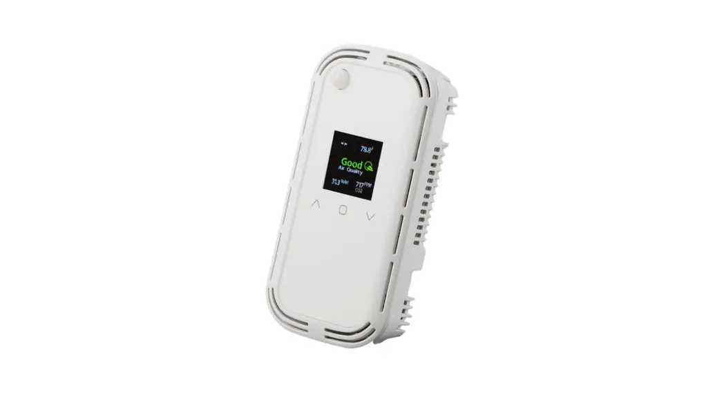
Indoor Air Quality Sensor
BACnet/Modbus/Analog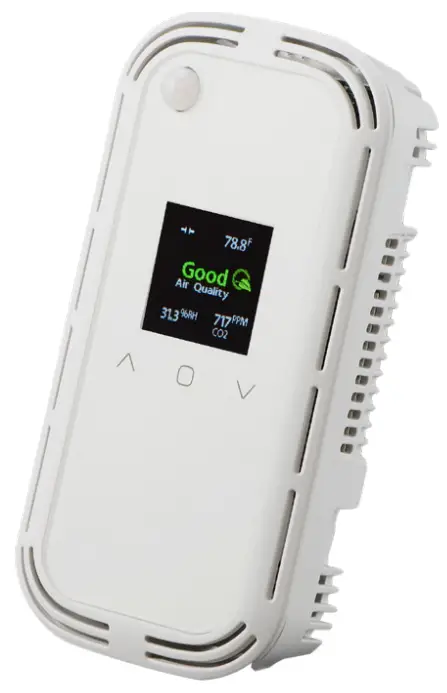
![]()
IMPORTANT WARNINGS
- Only qualified trade installers should install this product
- This product is not intended for life-safety applications
- Do not install in hazardous or classified locations
- The installer is responsible for all applicable codes
- De-energize power supply prior to installation or service
PRODUCT APPLICATION LIMITATION:
Senva products are not designed for life or safety applications. Senva products are not intended for use in critical applications such as nuclear facilities, human implantable devices, or life support. Seva is not liable, in whole or in part, for any claims or damages arising from such uses.
FEATURES
The TotalSense series design allows customization for a sensorthat meets project requirements for monitoring temperature,
carbon dioxide (CO2), total volatile organic compounds (TVOC), particulate matter (PM), relative humidity (RH), passive-infrared occupancy sensor (PIR), and ambient light.
The product can be ordered as a stand-alone CO2, RH, Temp,
TVOC, PM, or PIR sensors as well as almost any combination of sensors. Resistive-set-point sliders and pushbuttons are also available to meet the equirements for any job. All models come standard with a programmable set-point relay (except on PM models) and barometric pressure compensation for CO2. Choose the analog version to receive up to three selectable and programmable analog outputs or utilize the version of the communication to access a myriad of data through Modbus RTU or BACnet MS/TP. The communications version comes standard with ambient light sensing.
To verify the features see the ‘Product Identification’ section of the installation manual or use the configuration tool at senvainc.com or scan the QR code on the right.

PRODUCT IDENTIFICATION
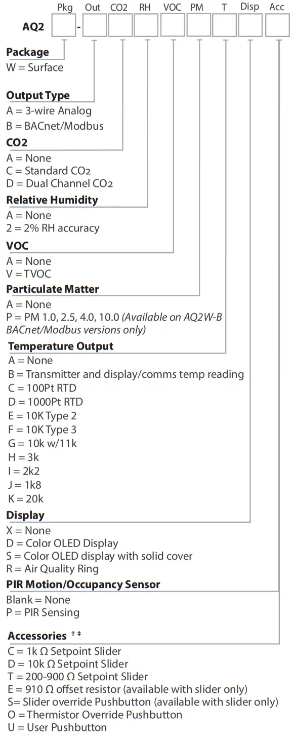
† Additional Setpoint sliders and offset resistors available upon request
‡ Slider and pushbutton options not available with PM sensor
INSTALLATION
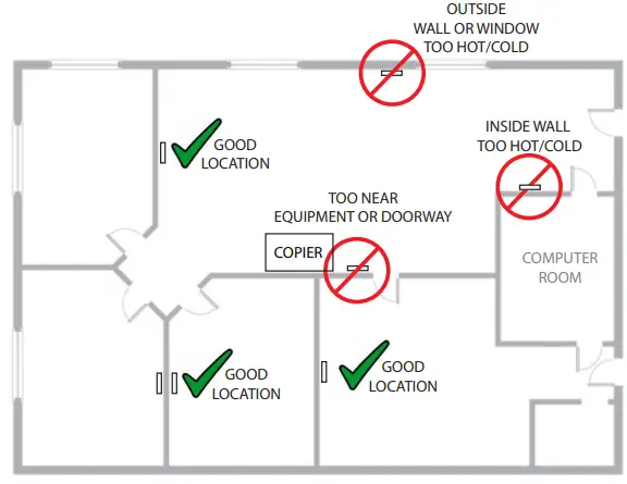
- IMPORTANT! Locate the device in an area away from ventilation sources and heat-generating equipment and appliances. The device should be mounted at light switch height in a vertical orientation. Use insulating material behind the device to ensure reading accuracy.
NOTE: Do not install the device in multi-gang electrical boxes with line voltage or other electrical devices.
- Wire according to application. See the “Setup- Wiring” section for details.
- Install the backplate to the wall or junction box using the screws provided. If using the optional trim ring, click the TotalSense into it and secure using 1 screw. Then, mount it to the wall or junction box.
- Apply power.
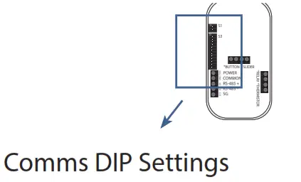
- To configure communications or analog voltage scaling, configure DIP switches according to the “Setup – Analog” or “setup – Communications” sections. To configure the device using the color OLED screen, reference the “Setup – Display” section. Comms Terminals Analog T
DIMENSIONS
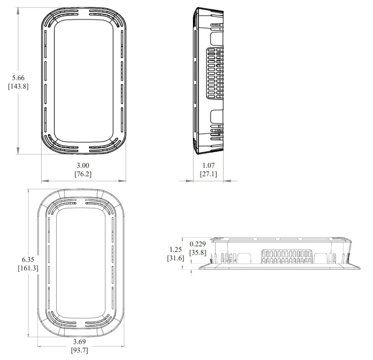
A concealment ring is provided to hide oversized cutouts or to mount using a European-sized junction box.
SETUP – WIRING
The following diagrams show terminal locations for each version of the total sense. The number of options selected will determine which of the terminals are included on each device, for example, if only one sensor is chosen, only 1 pair of analog terminals will be present. Each device will have 4-8 terminals
on the left side, 0-4 on the top, and 0-4 on the right side.
Analog Wiring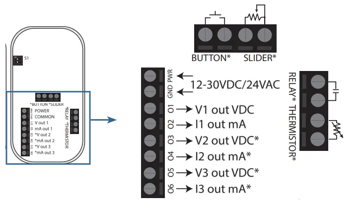 *These terminals may not be populated depending on which model is ordered.
Communications Wiring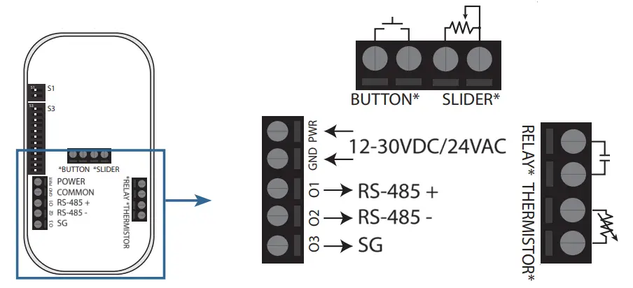
NOTE: A 120 Ω termination resistance may be added in parallel with the RS-485 +/- by moving the very top DIP switch (DIP 1) to the left position. See the “DIP Configuration” section for more information.
SETUP – ANALOG
Switch 1 with two DIP switches will be provided with every device and Switch 2 with an additional 12 DIP switches will be provided with communications devices. The following diagram shows how each setting can be configured using the provided switches.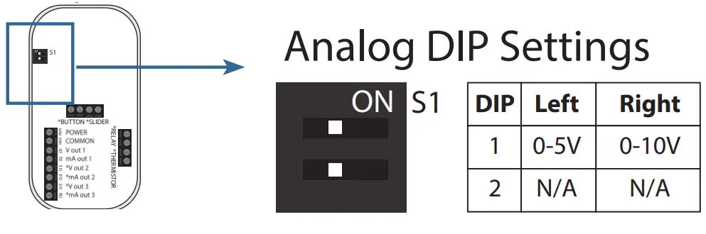 For analog voltage output, select either 0-5V (left) or 0-10V (right) outputs. These analog ranges can be adjusted using the color OLED display. Adjustments made using the OLED display will override this DIP switch setting.
SETUP – COMMUNICATIONS
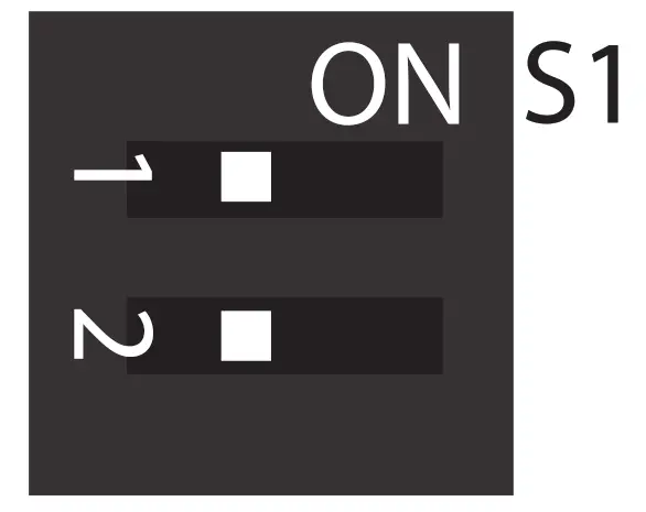
| DIP | Left | Right |
| 1 | N/A | Termination Resistor |
| 2 | Modbus | BACnet |
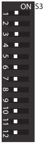
| DIP | Function | Left | Right |
| 1 | MAC6 | 0 (off) | 1 (on) |
| 2 | MAC5 | 0 | 1 |
| 3 | MAC4 | 0 | 1 |
| 4 | MAC3 | 0 | 1 |
| 5 | MAC2 | 0 | 1 |
| 6 | MAC1 | 0 | 1 |
| 7 | MAC0 | 0 | 1 |
| 8 | BAUD2 | 0 | 1 |
| 9 | BAUD1 | 0 | 1 |
| 10 | BAUD0 | 0 | 1 |
| 11 | D/P/S1 | 0 | 1 |
| 12 | D/P/S0 | 0 | 1 |
| DIP | Function |
| 1-7 | MAC Address/ Modbus Address 0-127 (binary) |
| 8-10 | Baud Rate 0(000)=9600 1(001)=19200 2(010)=38400 3(011)=57600 4(100)=76800 5(101)=115200 |
| 11-12 | Data/Parity/Stp 0(00)=8N1 1(01)=8N2 2(10)=8O1 3(11)=8E1 |
DIP switches 1-7 can be arranged in 127 binary configurations to set the MAC address (BACnet) or the Modbus address. Similarly, the baud rate can be set by DIP switches 8-10 and the data/parity/stop bit can be set by DIP switches 11 and 12.
ADVANCED SETUP
 | ||
| http://tny.sh/AQ2DisplayGuide | http://tny.sh/AQ2BACnet | http://tny.sh/AQ2Modbus |
SETUP – DISPLAY
Example screen:
otalSense devices ordered with color OLED display can be configured from the display or over communications (if applicable). The default screen layout will vary depending on which model is ordered. Each of the 5 sections can be customized. See “Display Navigation Guide” for information.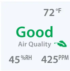
Screen Lock:
If the screen is locked, a lock icon will show when any button is pressed. To unlock, hold the UP and DOWN arrows for 5 seconds. To disable the lock feature, see “Display Navigation Guide”.
Changing Settings:
To change any setting, press ENTER to see the setup menu and navigate to the desired parameter type, and press ENTER again to choose. The example below shows how to adjust the center reading on the display. The dashed blue line shows the desired selections and the blue buttons show how to navigate.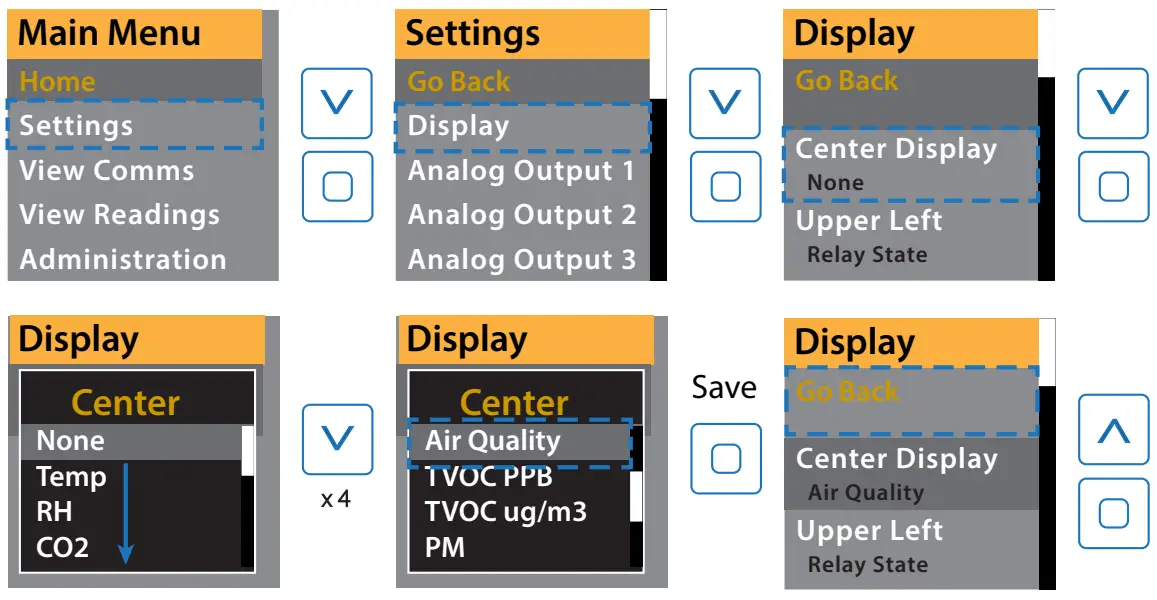 Changing a value:
To adjust a numerical setting, set each digit individually and press ENTER to move the cursor from left to right. When all digits are set, the value will be saved when ENTER is pressed again.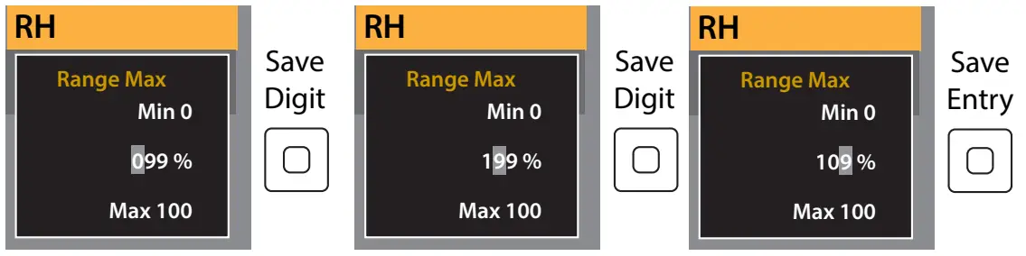
FEATURE – AIR QUALITY
If Air Quality is selected to be displayed or if the Air quality Ring option is selected, the device will monitor each CO2, VOC, PM, RH, and Temp sensor present and will display accordingly. The average air quality is calculated as follows:
- Each sensor’s current reading is rated according to the below thresholds and given an air quality index (AQI). For each sensor, a good rating is given an AQI of 90, fair is given an AQI of 60, and poor is given an AQI of 0
- The average air quality is calculated and a total air quality rating is assigned based on the following thresholds. These thresholds can be adjusted using communications or in the “Air Quality Settings” menu from the display.
a. Good ≥ 75
b. 55 < Fair < 75
c. Poor ≤ 55GOOD (AQI 90) FAIR (AQI 60) POOR (AQI 0) PM2.5 <35 ug/m3 35-55 ug/m3 >55ug/m3 TVOC <1000 ug/m3 1000-3000 ug/m3 >3000 ug/m3 CO2 <1200 PPM 1200-2000 PPM >2000 PPM Temp 64-79°F <64°F, >79°F RH 30-60% <30%, >60% <10%, >90%
FEATURE – PIR OCCUPANCY
If the PIR option is selected, the PIR (Passive Infrared) sensor will trigger anytime it detects motion. If used to activate the relay or as a communications data point, an off-delay can be programmed using the display or through communications. The below shows the distance at which the sensor will trigger
a motion event based on its adjustable sensitivity rating. A motion event, for the purpose of this graph, is considered the movement of a person or large object. 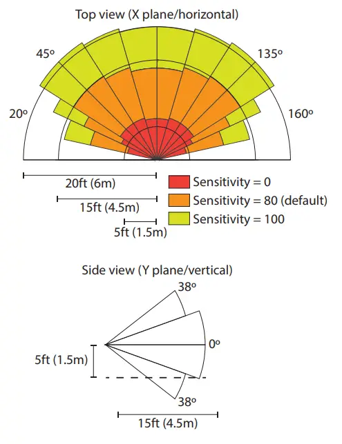
FEATURE – AIR QUALITY RING
An Air Quality (AQ) Ring may be selected in place of a display.
The AQ ring will glow green, yellow, or red according to the detected levels of CO2, PM, VOC, RH, and Temp. See the “Feature – Air Quality” section for thresholds. The AQ Ring may be disabled or brightness may be adjusted if the communications model is selected. Additionally, it may be set to only display yellow or red when air quality has degraded to fair or poor levels. See TotalSense “BACnet/Modbus User Guide” for more information. AQ Ring will turn on and off at a 5-second interval if a sensing error occurs. See the “Troubleshooting” section for information.
FEATURE – SETPOINT RELAY
All TotalSense models come standard with a setpoint relay except those ordered with a PM sensor. The relay source determines which reading or status will activate the relay. This can be set or adjusted using the display or communications. See ‘Display Navigation Guide’ or the applicable protocol guide for details. Each source selection has a range listed below. To set turnon and turn-off thresholds, a percentage of this range can be entered into each corresponding parameter. On display versions, the calculated value will show as the percentage is adjusted. Each time a new source is selected, a default relay threshold will be set based on which technology is chosen. These auto-set values are listed in the table below.
| Source Selection | Range | Default Turn-on Threshold | Calculated Turn-on value | Default Turn-off Threshold | Calculated Turn-off value |
| CO2 | 0-10,000 PPM | 8.% | 800 PPM | 7.% | 700 PPM |
| RH | 0-100% RH | 60% | 60% RH | 55% | 55% RH |
| Temp* | -40 – 122 °F | 74% | 80°F | 73% | 78°F |
| TVOC | 0-10000 pg/ m3 | 4% | 400 pg/m3 | 4.% | 350 pg/m3 |
*To calculate threshold % for a given temperature, use the following equation:
% Threshold = (T+40)/162*100
Where T is the temperature in °F
TVOC OPERATION
Training Mode
The TVOC sensor has artificial intelligence (AI) that allows it to sense and understand different environments. This AI may take up to 7 days to acclimate o an environment once installed. For this reason, a TVOC reading is not included in the Air Quality calculation until it has been powered for 7 days. During this time, the sensor will go into “training mode” and will not display or output a TVOC value. Instead, the display will show “Training days” where X” is how many days the device has been in training mode and 7 days is the expected duration. Once it reaches 7 days, reading will be shown. Using communications, the TVOC reading will show a countdown from -7 to 0 days; once it hits zero the device will switch into normal operation. 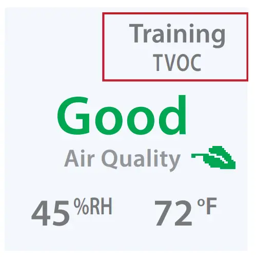
Manual Calibration
No manual field calibration is necessary. To maintain accuracy TVOC sensor will be required to be exposed to fresh air at least once every 10 days. This can be accomplished by increasing airflow in an area or by opening a window.
Scaling:
Seva’s TVOC sensor uses an Ethanol reading to determine a raw TVOC value. Additionally, conversion from µg/m3 uses the molecular weight of Ethanol. To scale based on a different gas baseline, the user may enter a scaling factor in TVOC Settings on the display or user communications.
CO2 CALIBRATION
Automatic Calibration feature:
The CO2 sensor will automatically baseline CO2 levels and gradually make adjustments to compensate for sensor drift due to the long-term aging of the IR light source. In applications where CO2 levels are continuously elevated, or spaces are occupied day and night, it is recommended to use our dual channel CO2 sensor with automatic calibration disabled. Seva CO2 sensors are factory calibrated to control test gases. No field calibration is necessary or recommended. However, to facilitate compliance with job requirements and commissioning procedures, provisions for field calibration are provided:
- Locate calibration instruments and sensors in close proximity to each other in a controlled environment free of drafts, people, and equipment to reduce the influence on CO2 and temperature.
- Compare the output of the sensor to the calibration instrument, and note the difference. (In 0-10V mode/2000ppm range, 1V =200ppm) Refer to the “Setup- display” section to adjust the offset value for CO2 as needed. Factory calibration may be restored by setting the offset back to 0. In extreme cases where the sensor module has been damaged, a new module may be installed in the field. Consult the factory for replacement modules and instructions.
TROUBLESHOOTING
| Symptom | Solution |
Ring | The device has experienced an error with one of the sensors. Navigate to the “Advanced Settings” > “Diagnostics” screen to view more information. All zeros will be displayed if no error is present. See “Display Navigation Guide”, or the applicable communications guide or consult the factory for troubleshooting help or replacement element. |
| No output | Check to wire. Ensure the power supply meets requirements. |
| Reading error | Verify control panel software is configured for correct output scaling. |
| Verify the accuracy of the test instrument. Observe installation and calibration guidelines. | |
| Verify unit is located away from sources of hot/ cold. | |
| Verify sensing element is inserted properly. | |
| Perform calibration only if necessary. |
SENVA TECHNICAL SUPPORT
Need further assistance? Call our toll-free number for live technical support: (866) 660-8864 or feel free to email us at [email protected]
SPECIFICATIONS
| Power Supply | Without Display With LED Ring or Display | 16-30VDC/24VAC(1), 3.5W nominal, 4W max. 24-30 VDC/24VAC(1), 4.3W nominal, 5W max | |
| Interface | Color OLED (optional) | 1.5” Organic LED Display, 128×128 PX, color | |
| Air Quality Ring | Color changing (red/yellow/green) LED ring | ||
| Analog Outputs (Analog version only) | Quantity | Up to 3 outputs | |
| Source | CO2, RH%, Temp, Temp slider, TVOC (selectable) | ||
| Scale | 0-5V, 0-10V, 4-20mA (switch selectable, programmable per output) | ||
| Protocol Output (Communications version only) | Protocol | BACnet MS/TP or Modbus RTU | |
| Connection | 3-wire RS-485, with isolated ground | ||
| Data Rate | 9600, 19200, 38400, 57600, 76800, 115200 (switch selectable) | ||
| Address Range | 0-127 | ||
| Relay Set-point (standard except for PM models) | Type | Solid-state output, 1A @ 30VAC/DC, N.O. | |
| Source | CO2 setpoint, RH setpoint, Temp setpoint, TVOC setpoint, PIR motion, air quality, off (selectable) | ||
| Polarity | NO/NC (selectable) | ||
| CO2 (optional) | Type | Non-dispersive Infrared (NDIR) | |
| Accuracy | ±(30ppm + 3% of reading) (400-2000ppm), -10-50ºC, 0-85%RH ±(50ppm+ 5% of reading) (2000-5000ppm), -10-50ºC, 0-85%RH >5000ppm consult factory | ||
| Resolution | 1 ppm | ||
| Range | 0-2000 PPM (Default) (Programmable up to 10,000 PPM) | ||
| Response time | 90 seconds to 90% reading | ||
| Sample rate | 1s | ||
| Temp and Pressure | Compensated. Barometric pressure also readable over communications | ||
| Relative Humidity (optional) | Type | Digital CMOS | |
| Accuracy(2) | ±2% over 0 to 80%RH range | ||
| Resolution | 0.05%RH | ||
| Response time (3) | 30s | ||
| Sample rate | 3s | ||
| Operating range | 0 to 100%RH (non-condensing) | ||
| Operating conditions (4) | -4 to 140oF (-20 to 60° C) @ RH>90%; -4 to 176oF @ RH=50% | ||
| Temperature Transmitter (optional) | With RH option | Without RH option | |
| Type | Silicon Band-gap | NTC Thermistor | |
| Nominal Accuracy | ±0.3° C (operating range) | ±0.5° C (operating range) | |
| Maximum Accuracy (2) | ±0.5° C (at 25° C), ±1.0° C | ±1.0° C (at 25° C), ±2.0° C | |
| Resolution | 0.01° C | 0.05° C | |
| Response time | 30s | 30s | |
| Sample rate | 3s | 100ms | |
| TVOC (optional) | Type | MOS | |
| Gas | Total VOC | ||
| Range | 0-10,000 μg/m3 | ||
| Response Time | <10s | ||
| Temp, Pressure | Compensated | ||
| Output | 0-2000 μg/m3 (default) Programmable up to 10,000 μg/m3 | ||
| PMx (optional) CLASS 1 LASER PRODUCT | Type | Optical | |
| Size Range | PM1.0, PM2.5, PM4.0, PM10.0 | ||
| Scale | 0-1000 μg/m3 | ||
| Lower detection limit | 0.3 μm | ||
| Precision | ±10 μg/m3 (0-100μg/m3); ±10% (100-1000 μg/m3) | ||
| PIR (optional) | Type | Passive Infrared | |
| Axis X field of view | 140o, 15 ft (4.5m) | ||
| Axis Y field of view | 76o, 15 ft (4.5m) | ||
| Ambient Light | Type | Phototransistor | |
| Scale | 0-100 FC (lm/ft2), readable over communications | ||
| Operating Environment | Temperature | 32 to 122oF (0 to 50oC) | |
| Humidity | 0-95% non-condensing | ||
| Enclosure | Material | ABS Plastic | |
| Dimensions | 5.67”h x 3.00”w x 1.07”d | ||
| Compliance | Agency | CE, RoHS | |
- One side of the transformer, the secondary is connected to the signal common. A dedicated transformer is recommended.
Issued 7/28/2021 Document #152-0401-0C - Models with PM sensors included achieving ±5% accuracy over the 0 to 80%RH range and an additional temperature shift of up +0.5° C
- Time for reaching 63% of reading at 25° C and 1 m/s airflow
- Long-term exposures to conditions outside the normal range at high humidity may temporarily offset the RH reading (+3%RH after 60 hours.)
![]()


