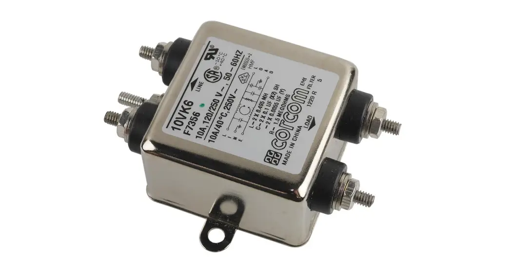
![]() VK6 K Series Corcom General Purpose RFI Power Line Filter
VK6 K Series Corcom General Purpose RFI Power Line Filter
User Guide
![]() UL Recognized CSA Certified VDE Approved**
UL Recognized CSA Certified VDE Approved**
K Series
- Suitable for high-impedance loads
- Well suited to applications where pulsed, continuous, and/or intermittent RFI interference is present
- EK models meet the very low leakage current requirements for VDE portable equipment and non-patient care medical equipment
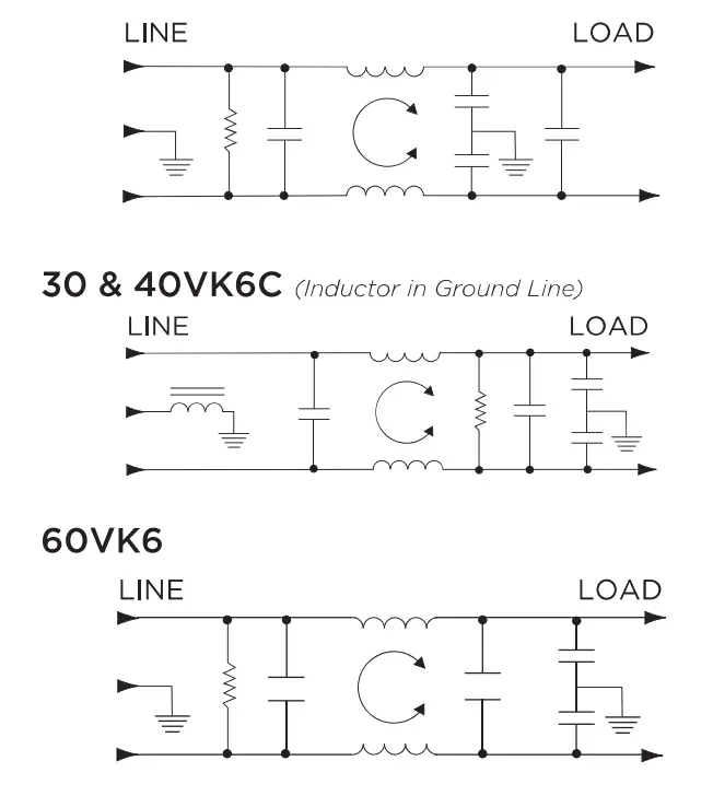
- Available with ground line inductor (choke)
Ordering Information

*1-75A: IEC 60320-1 C14 inlet mates with C13 connector
20VK7: C20 inlet mates with C79 connector

Specifications
Maximum leakage current each Line to Ground:
| VK Models | EK Models | |
| @ 120 VAC 60 Hz: | .5 mA | .21 mA |
| @250 VAC 50 Hz: | 1.0 mA | .36 mA |
Hipot rating (one minute):
| The line to Ground: | 2250 VDC |
| Line to Line: | 1450 VDC |
| Rated Voltage (max): | 250 VAC |
| Operating Frequency: | 50/60 Hz |
| Rated Current: | 1 to 60A* |

Available Part Number
| DIROZ | DIRZ | 2>IAOL |
| VIL>130L | 2>13L | LNAOL |
| L>IROL | DIRL | klbiAS |
| 2>I3OL | 9>1A09 | blAS |
| DI3OL | 09>IA017 | 2>IAS |
| WEARS | 9>IA017 | LNAS |
| L>199 | D9NA02 | IAJLAA2 |
| 2>119 | 9>IA02 | L.>IA2 |
| DIDS | *DIAOZ | >1A2 |
| WL>132 | 9>IAOZ | DIA2 |
| L>I32 | DIAOZ | 2NAZ |
| 2>112 | lAIDIAOL | DIAZ |
| LN12 | LAAOL | 2NAL |
| 2>ISZ | 9NAOL | DIAL |
**20VK7, 20A model tested by Underwriters Laboratories to US and Canadian requirements and is VDE approved at 76A, 250VAC
Electrical Schematics
Accessories
GA400: NEMA 5-15P to IEC 60320-1 C-13 line cord

Case Styles

Typical Dimensions:
| ( Line/Load Terminals (4): | ..250 [6.3] with .07 [1.8] Dia. hole |
| Ground Terminal (1): | .250 [6.3] with .07 x .16 [1.8 x 3.8] slot |
| Mounting Holes (2): | .188 [4.78] Dia. |

Typical Dimensions:
| ( Line/Load Terminals (4): | ..250 [6.3] with .07 [1.8] Dia. hole |
| Ground Terminal (1): | .250 [6.3] with .07 x .16 [1.8 x 3.8] slot |
| Mounting Holes (2): | .188 [4.78] Dia. |

Typical Dimensions:
| Wire Leads (5): | 4.0 [101.6] Min., AWG18 (AWG16 for 10A) |
| Mounting Holes (2): | .188 [4.78] Dia. |

Typical Dimensions:
| Terminals (5): | 8-32, Torque 18 Ibf-in. [2.03 N-m] max. ± 2 [.22] |
| Mounting Holes (2): | .188 [4.78] Dia. |

Typical Dimensions:
| Terminals (5): | 8-32, Torque 18 Ibf-in. [2.03 N-m] max. ± 2 [.22] |
| Mounting Holes (2): | .188 [4.78] Dia. |
30 VK6/6C & 40VK6/6C 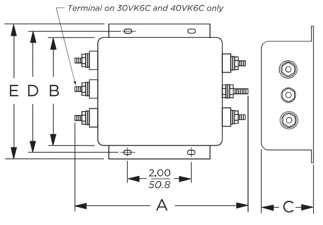 Typical Dimensions:
| Terminals (5): | B-32, Torque 18 Ibf-in. [2.03 N-m] max. ± 2 [.22] |
| Mounting Slots (4): | .250 x .156 [6.35 x 3.96] Dia. |
60VK6
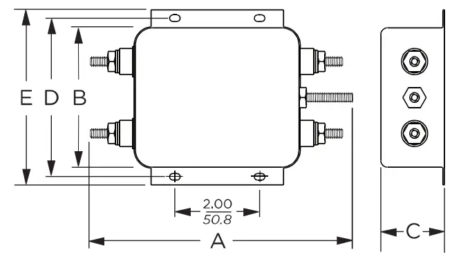
Typical Dimensions:
| Terminals (5): | B-32, Torque 18 Ibf-in. [2.03 N-m] max. ± 2 [.22] |
| Mounting Slots (4): | .250 x .156 [6.35 x 3.96] Dia. |
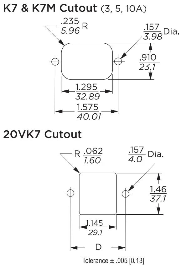
K7 & K7M ( 3.5.10A)

Typical Dimensions:
| Load Terminals (2): | .250 [6.3] with .07 [1.8] Dia. hole |
| Ground Terminal (1): | 250 [6.3] with .07 x .16 [1.8 x 3.8] slot |
| Line Inlet (1): | IEC 60320-1 C14 |
| K7 Tapped Inserts (2): | 6-32 x 1/4 |
| K7M Tapped Inserts (2): | M3 x .5 |
20VK7

Typical Dimensions:
| Load Terminals (2): | .250 [6.3] with .07 [1.8] Dia. hole |
| Ground Terminal (1): | 250 [6.3] with .07 x .16 [1.8 x 3.8] slot |
| Line Inlet (1): | IEC 60320-1 C14 |
| K7 Tapped Inserts (2): | 6-32 x 1/4 |
| K7M Tapped Inserts (2): | M3 x .5 |
Case Dimensions
| Part No. | A (max) | B (max) | C (max) | D ± .015 ±38 | E (max) |
| 1VK1, 1EK1, 2VK1, 2EK1 | 3.1 78.7 | 2.07 52.6 | 0.91 23.1 | 2.375 60.33 | 2.81 74.1 |
| 1VK3, 1EK3, 2VK3, 2EK3 | 1.81 46.0 | 2.07 52.6 | 0.91 23.1 | 2.375 60.33 | 2.81 74.1 |
| 3VK1, 3EK1, 5VK1, 5EK1 | 3.10 78.7 | 2.07 52.6 | 1.16 29.5 | 2.375 60.33 | 2.81 74.1 |
| 3VK3, 3EK3, 5VK5, 5EK3 | 1.81 46.0 | 2.07 52.6 | 1.16 29.5 | 2.375 60.33 | 2.81 744 |
| 3V K7/7 M , 3EK7/7M | 3.21 81.5 | 2.25 57.2 | 1.28 32.5 | 1.575 40.01 | 0.63* 16.0* |
| 5VK7/7M, 5EK7/7M | 3.21 81.5 | 2.25 57.2 | 1.28 32.5 | 1.575 40.01 | 0.63* 16.0′ |
| 10VK1, 10EK1 | 3.35 85.1 | 2.07 52.6 | 1.16 29.5 | 2.375 60.33 | 2.81 71.4 |
| 10VK3, 10EK3 10VK6 | 2.07 52.6 3.46 87.9 | 2.07 52.6 2.07 52.6 | 1.16 29.5 1.16 29.5 | 2.375 60.33 2.375 60.33 | 2.81 71.4 2.81 71.4 _ |
| 10VK7/7M, 10EK7/7M | 3.71 94.2 | 2.25 57.2 | 1.28 32.5 | 1.575 40.01 | 0.63* 16.0′ |
| 20V K1, 20EK1 20VK6 20VK7 | 3.35 85.1 3.46 87.9 3.8 90.4 | 2.56 65.0 2.56 65.0 2.28 54.6 | 1.53 38.9 1.53 3&9 1.78 39.6 | 2.938 7463 2.938 _ 74.63 1.575 74.63 | 3.35 85.1 3.35 _ 85.1 .846′ 85.8′ |
| 30VK6, 30VK6C | 5.34 135.6 | 3.38 85.9 | 1.53 38.9 | 3.75 95.25 | 4.20 106.7 |
| 40VK6, 40VK6C | 134 135.6 | 3.38 85.9 | 1.53 38.9 | 3.75 95.25 | 4.20 106.7 |
| 60VK6 | 6.0 152.4 | 3.38 85.9 | 1.53 38.9 | 3.75 95.25 | 4.20 106.7, |
Recommended panel Cutouts
Performance Data
Typical Insertion Loss
Measured in closed 50 Ohm system


| Frequency – MHz | ||||||
| Current Rating | 0.15 | 0.5 | 1 | 5 | 10 | 30 |
| Vk Models | ||||||
| 1, A | 15 | 30 | 30 | 50 | 50 | 50 |
| 2,A 5A, 10,A | 6 | 19 | 38 | 42 | 45 | 50 |
| 20A | 6 | 19 | 28 | 42 | 45 | 50 |
| 30A, 40A | 6 | 19 | 28 | 42 | 45 | 50 |
| 60A | 6 | 22 | 28 | 32 | 39 | 35 |
| Ek Models | ||||||
| 1A,3A | 15 | 29 | 35 | 45 | 45 | 50 |
| 2A,5A,10A | 8 | 19 | 25 | 38 | 40 | 45 |
| 20A | 8 | 19 | 25 | 38 | 40 | 45 |
| Frequency – MHz | ||||||
| Current Rating | 0.15 | 0.5 | 1 | 5 | 10 | 30 |
| Vk Models | ||||||
| 1A,3A | – | – | 48 | 55 | 50 | 35 |
| 2,A 5A, 10,A | – | – | 30 | 50 | 30 | 30 |
| 20A | 6 | 6 | 30 | 50 | 30 | 30 |
| 30A, 40A | 2 | 40 | 60 | 65 | 57 | 55 |
| 60A | 13 | 49 | 67 | 57 | 53 | 53 |
| Ek Models | ||||||
| 1A,3A | – | – | 48 | 55 | 50 | 35 |
| 2,A 5A, 10,A | – | – | 30 | 50 | 30 | 30 |
| 20A | 6 | 6 | 30 | 50 | 30 | 30 |
Dimensions are in inches and millimeters unless otherwise specified. Values in italics are metric equivalents. Dimensions are shown for reference purposes only. Specifications are subject to change.
For email, phone or live chat, please go to
te.com/help
corcom.com


