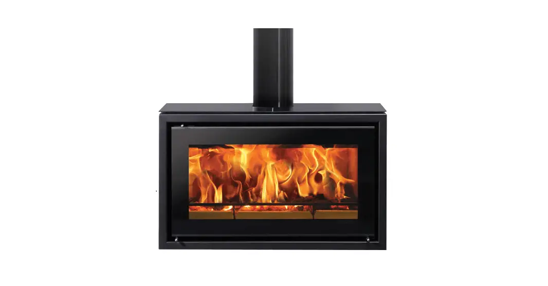

STOVAX RVFST-1EU Freestanding Range
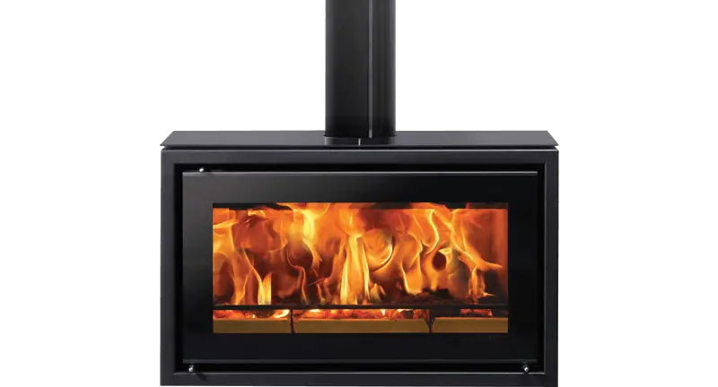
Freestanding Range
| Studio 1 | RVFST-1EU |
| Studio 2 | RVFST-2EU |
| Studio 3 | RVFST-3EU |
ESSENTIAL INFORMATION
| GENERAL | Model:
Studio 1 Studio 2 Studio 3 |
Studio 1 |
Studio 2 |
Studio 3 | ||
| Nominal Heat Output | Wood | kW | 5.0 | 8.5 | 12.6 | |
| Efficiency | Wood | % | 77.8 | 76.3 | 76.1 | |
| CO @ 13% O2 | Wood | % | 0.11 | 0.11 | 0.1 | |
| Weight | Kg | 76 | 83 | 120 | ||
| Recommended Fuels | Wood | Seasoned Wood (less than 20% moisture content) | ||||
As tested to the requirements of EN 13229 for intermittent operation
| FLUES |
Flue/Chimney Size | With Liner of Factory made system (diameter) installed in accordance with manufacturers instructions | mm | 153 | 153 | 153 |
| inch | 6 | 6 | 6 | |||
| Flue/Chimney minimum height | All products | m | 4.5 | 4.5 | 4.5 | |
| feet | 15 | 15 | 15 | |||
|
Flue Draught | Min |
Pa | 10 | 10 | 10 | |
| Nominal | 12 | 12 | 12 | |||
| Max | 20 | 20 | 20 | |||
| Flue Gas Mass Flow | Wood | g/s | 4.9 | 7.7 | 9.3 | |
| Average Flue Gas Temperature | Wood | oC | 276 | 304 | 361 | |
| Flue Outlet Size (Top Option) | mm | 153 | 153 | 153 | ||
| inch | 6 | 6 | 6 |
European Min Spec for Solid Fuel Chimney Flue – T400 N2 D 3 G50
| VENTILATION | A) Traditionally Built Homes • Where leakage is greater than 5m3/hour/m2. • Ventilation normally required = 550mm2 per kW output over 5kW | B) Modern Construction Homes • Where leakage is less than 5m3/hour/m2. • Ventilation normally required = 550mm2 per kW | ||||
| A | Additional Ventilation | mm2 | None | 1650 | 3850 | |
| cm2 | None | 16.5 | 38.50 | |||
| in2 | None | 2.6 | 5.3 | |||
| B |
Additional Ventilation | mm2 | 2750 | 4400 | 6600 | |
| cm2 | 27.5 | 44 | 66.0 | |||
| in2 | 4.44 | 7.1 | 10.65 | |||
‡In the U.K. Additional information covering the installation of the appliance may be found in the following British Standards: BS EN 15287, BSEN1856-2:2009, BS8303.
GENERAL INFORMATION
Installing the Appliance
Each installation is unique to the property so it is not possible to give details to suit every setting. The installation must comply with Building Regulations and be made using “best practice” construction methods. Take care when installing the appliance. Careless handling and use of tools can damage the finish and/or area.
Appliance Location
Many fireplace openings have a supporting lintel. Do not remove without supporting the remaining structure of the building. Do not support the structure with the appliance or the flue system.
If installing with a Dedicated External Air Kit, please consult manual PM1690 prior to installation
Registered Professional:
Before installation and/or use of this appliance please read these instructions fully and carefully to ensure that you have fully understood their requirements.
The appliance must be fitted by a registered installer, or approved by your local building control officer.
Structural Support:
If installing on a wooden floor check that the floor joists are strong enough to bear the weight of the insert, chimney and construction parts.
Hearth:
A Constructional Hearth with a depth of 125mm and a 12mm. Decorative Hearth Plate must be installed to protect a combustible floor from the risk of falling embers if mounted directly on the floor.
The Decorative Hearth must extend 300mm in front of the hearth and can be made of natural stone, concrete, metal or glass.
Final inspection of the installation:
When it has been installed, the appliance must be commissioned in accordance with standards and practices to ensure full working order and a correct handover given to the customer.
Flue and Chimney
- The flue or chimney system must be able to withstanding flue temperatures of up to 4000C.
- The external diameter of the connection sleeve is 155mm.
- In normal operating mode, draft in the chimney should be 20-25 Pa close to the connection sleeve. The draft is affected primarily by the length and area of the chimney and also by how well sealed it is.
- The minimum recommended chimney length is 3.5m and a suitable cross-section area is 150-200cm² (140-160 mm in diameter).
- Sharp bends and horizontal lengths in a flue pipe reduce the draft in the chimney.
- It must be possible to sweep the full length of the flue, and the soot doors must be easily accessible.
- Carefully check that the chimney is sealed and that there is no leakage of smoke from the connections.
Combustion Air Supply
- When the appliance is installed, it is essential to ensure adequate air is supplied to the room. Air can be provided indirectly via a vent in the outer wall or via a duct from the outside that connects to the sleeve on the underside of the insert. The required volume of combustion air is about 20 m3/hour.
- The outer diameter of the combustion air connection sleeve is 80mm. If a pipe is longer than 1 m, its diameter must be increased to 100mm and a larger wall vent will be required.
- In heated spaces, the flue must be insulated to prevent condensation using 30mm mineral wool covered with a vapour barrier. The hole in the wall (or floor) at the exit point must be properly sealed with flue jointing compound.
- A flexible pipe to provide external directly into the appliance is available and must be fitted at the time of installation.
CO Alarms
Building regulations require that whenever a new or replacement fixed solid fuel or wood/biomass appliance is installed in a dwelling a carbon monoxide alarm, complying with BS EN50291, must be fitted in the same room as the appliance.
HETAS recommend the unit is permanently fixed in accordance with the manufacturer’s installation instructions or with the guidance contained in Approved Document J where no other information is available. Provision of an alarm must not be considered a substitute for either installing the appliance correctly or ensuring regular servicing and maintenance of the appliance and chimney system.
PRODUCT FICHE – Information Requirement for Solid Fuel Local Space Heater
| Model |
Studio 1 |
Studio 2 |
Studio 3 |
| Direct Efficiency Class | A | A | A |
| Direct Heat Output (kW) | 5.0 | 8.5 | 12.6 |
| Indirect Output (kW) | – | – | – |
| Energy Efficiency Index (EEI) | 104 | 102 | 101 |
| Useful Energy Efficiency at Nominal Heat Output | 77.8% | 76.3% | 76.1% |
| Safety Precautions | Appliance must be installed, Used and Maintained in accordance with the manufacturers instructions supplied | ||
PRODUCT MATERIAL INFORMATION
The following substances, preparations or components should be disposed of or recovered separately from other WEEE in compliance with Article 4 of EU Council Directive 75/442/EEC.
| Metal | Steel | Can be taken to a local recycling centre for reuse to reduce waste going to landfill. |
| Cast iron | ||
| Glass | Can be taken to a local recycling centre for reuse to reduce waste going to landfill. | |
| Vermiculite linings | Non hazardous material. Vermiculite can be crushed up and used for plant bedding and ash used for composting or disposed of at a local recycling centre for reuse to reduce waste going to landfill. | |
|
Rope seals | Rope seals are made from Refractory Ceramic Fibre (RCF), a material which is commonly used for this application. Protective clothing is not required when handling these articles, but it is recommended to follow normal hygiene rules of not smoking, eating or drinking in the work area and always wash hands before eating or drinking. When servicing the appliance it is recommended that the replaced items are not broken up, but are sealed within heavy duty polythene bags and labelled as RCF waste. RCF waste is classed as stable, non-reactive hazardous waste and may be disposed of at a licensed landfill site. | |
| Electrical components | (Fan kits etc if applicable) | Dispose of at a local recycling centre in accordance with the WEEE directive. |
SMOKE CONTROL
SMOKE CONTROL KITS
These instructions apply to the Studio 1 & 2 models when fitted with a Smoke Control kit.
NOTE: These appliances have been independently tested to PD6434 and have been exempt from the controls that generally apply in smoke control areas hence are considered suitable for use in Smoke Control Area when burning wood and ONLY when fitted with the relevant Smoke Control kit detailed below.
| Product Code | Appliance | Smoke control kit Part No. |
| RVST-1EU | Riva Studio 1 | RVS-MEC11860 |
| RVST-2EU | Riva Studio 2 |
To meet the Smoke Control requirement this appliance MUST be operated correctly in order to minimise the amount of smoke produced.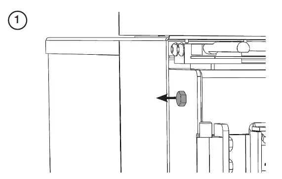
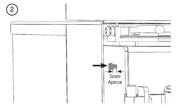
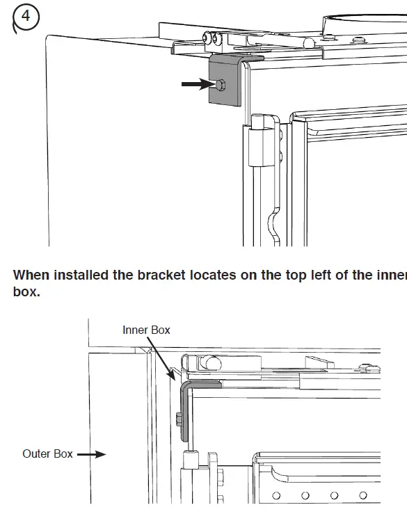
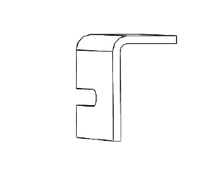
FITTING THE SMOKE CONTROL KIT STUDIO 1 & 2 ONLY
The Smoke Control kit for this product is a sliding bracket that prevents the Airwash slider from completely shutting down, allowing a small amount of air into the firebox to aid clean combustion.