
VOXX APS25Z Electronics Prestige Car Alarm System
INSTALLATION
This manual assumes the installer has adequate knowledge of the following expertise. Therefore, it does not cover these topics in detail:
- 12-volt electronics
- Testing and verifying circuits
- Making safe and lasting wiring connections
- Factory ignition, power, lighting, data bus and sensing systems
- Factory systems and components to avoid
- Safe wire routing, circuit protection and product placement
- Access to vehicle-specific technical information
In addition, this manual assumes the installer has the proper tools, skill and facilities to perform a professional installation. Performing an improper installation could result in damage to the vehicle or its components, improper system function, unsafe vehicle operation or physical injury. Such instances would not be covered by the vehicle manufacturer’s warranty, nor by Voxx Electronics, Inc.
Detailed Descriptions
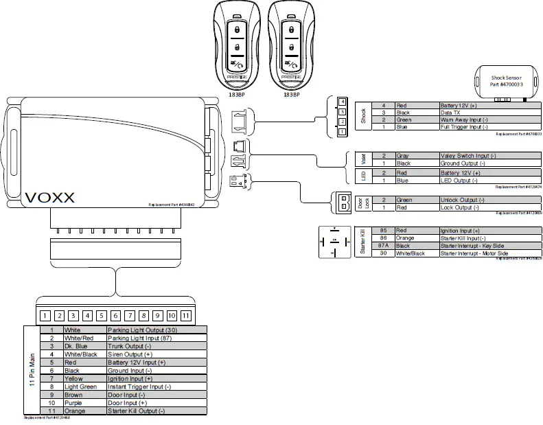
Wire Harness Colors and Functions
Main Input / Output Connector (11-pin connector)
These wires are listed in order of their placement in the harness connector
| 1 | 2 | 3 | 4 | 5 | 6 | 7 | 8 | 9 | 10 | 11 |
- WHITE – Parking Light Relay Output
- At its default setting, the WHITE wire supplies 12-Volt (+) or Ground (-) to the vehicle’s park light wire based on the connection of the relay input (WHITE/RED wire). Verification: The vehicle parking light wire registers 12-Volt (+) or Ground (-) when the park lights are turned on. Note: This wire can be programmed to perform the Trunk Release Output function by changing its options. Refer to Bank 2, Feature 6 on page 8.
- WHITE/RED – Parking Light Relay Input (Internal Relay Pin 87)
- The WHITE/RED connects to vehicle 12-Volt (+) or Ground (-) to supply the relay output (WHITE wire). Verification for default setting: • If the vehicle parking light wire registers 12-Volt (+) when the park lights are on, connect the WHITE/RED wire to a constant 12-Volt (+) vehicle wire. • If the vehicle parking light wire registers Ground (-) when the park lights are on, connect the WHITE/RED wire to a reliable vehicle ground source. Note: This wire can be programmed to perform the Trunk Release Output function by changing its options
- DARK BLUE – Trunk Release Output (-)
- At its default setting, the DARK BLUE wire connects to the vehicle trunk release wire or relay and supplies Ground (-) when activated from the remote control. Verification: The vehicle trunk release wire registers 12-Volt (+) or Ground (-) when the trunk release button is activated. Note: This wire can be programmed to perform the Parking Lights Output function by changing its options.
- WHITE/BLACK – Siren Output (+)
- The WHITE/BLACK wire supplies 12-Volt (+) to power the siren. After mounting the siren, connect its BLACK wire to a reliable ground source, and connect the BROWN wire to the siren’s RED wire.
- RED – 12-Volt Input (+)
- The RED wire connects to the vehicle’s primary 12-Volt (+) wire to power the system. Verification: The power wire registers 12-Volt (+) at all times. Note: Before making this connection, remove all module fuses until the system is completely connected.
- BLACK – Ground Input (-)
- The BLACK wire connects to a reliable vehicle ground (-) source to power the system. Verification: The vehicle ground (-) source wire registers ground (-) at all times. Note: Before making this connection, remove all module fuses until the system is completely connected.
- YELLOW – Ignition Input (+)
- The YELLOW wire connects to the vehicle’s primary ignition wire. This wire will be used for system programming and override. Verification: This ignition wire registers 12-Volt (+) when the key is in the accessory, ignition, and start positions. Note: Before making this connection, remove all module fuses until the system is completely connected
- LIGHT GREEN – Instant Trigger Input(-)
- The LIGHT GREEN wire connects a device or switch that, when triggered, supplies a Ground (-) output. If the system is armed, this input will trigger the alarm.
- BROWN – Door Trigger Input (-)
- The BROWN wire connects to the vehicle’s door trigger wire. This wire will detect Ground (-) input. Verification: The vehicle door trigger wire registers Ground (-) when a door is opened and opposite when closed. Note: If the door registers as 12-Volt (+) when the door is opened, use the PURPLE (Pin 3) input.
- PURPLE – Door Trigger Input (+)
- The PURPLE wire connects to the vehicle’s door trigger wire. This wire will detect a 12-Volt (+) input. Verification: The vehicle door trigger wire registers 12-Volt (+) when a door is opened and opposite when closed. Note: If the door trigger registers as Ground (-) when a door is opened, use the BROWN, Pin 8, input.
- ORANGE – Starter Kill Output N.C. (-)
- The ORANGE wire supplies Ground (-) when the alarm is armed
Door Lock Connector (2-pin connector)
- RED – Door Lock (-)
- The RED wire supplies Ground (-) when the Lock function is activated from the remote control or system. Verification: The vehicle lock wire registers 12-Volts (+) or Ground (-) when the Lock button is activated. Note: Additional parts may be required. See Page 11 for common door lock wire diagrams.
- GREEN – Door Unlock (-)
- The GREEN wire supplies Ground (-) when the Unlock function is activated from the remote control or system. Verification: The vehicle lock wire registers 12-Volt (+) or Ground (-) when the Unlock button is activated. Note: Additional parts may be required. See Page 11 for common door lock wire diagrams
External Components & Operation
Shock Sensor
The shock sensor plugs into a 4-pin connector on the Prestige module. It should be securely attached to a vehicle surface or sturdy wire harness. Testing takes place after all connections are made and the system is powered up. Refer to Quick Reference: System Diagnostics on page 10 for instructions on testing and adjusting the shock sensor.
LED / Valet Programming Port
The LED / Valet Programming port is used to for feature programming and Valet Override.
- Find a sutiable location to mount the supplied LED / Valet Programming button. Locate a clear spot on the vehicle’s dashboard that will be seen from the outside of the vehicle.
- Drill a 5/16 inch hole and mount the LED / Valet button. Route the wires to module and plug into proper location.
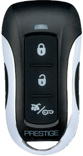
Remote Control Operation
This system includes two (2) 1-Way three (3) button remotes. The matrix below describes the basic functions of each remote. See Owners Guide for complete remote operation matrix.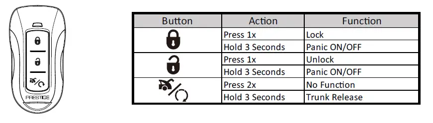
Valet Alarm Override
The Valet Override procedure will disable the alarm when the remote is not available or has become inoperative. If the vehicle door is opened without disarming, the alarm will sound and the vehicle will not start when attempting to start with the key. To disable the alarm:
- Turn the vehicle ignition to ON.
- Within 5sec, press and release valet button on Antenna 1x.
The alarm will silence and the vehicle will now start normally with the key
Setup Options
Bank 1: Add / Remove Remote Controls
Remote programming is located in Feature Bank 1. This system will Auto Program basic functions of the remote with one (1) button press. Basic functions are channels 1-3, Lock, Unlock, and Trunk / Start
| Feature Bank 1 | Description | ||
| CH. | 1 | Auto Program/Lock | Press Lock button on remote |
| 2 | Unlock | Press Unlock button on remote | |
| 3 | Trunk/Start | Press Start button on remote | |
To Auto Program a remote control:
- Turn the ignition key to ON.
- Press and release the valet/override button three (3) times.
- The system will beep one (1) time, indicating you have accessed Bank 1, Remote Programming.
- Press the Lock button of each remote control you wish to program. (Channels 1-3 of the remote control will be programmed.) The system will beep one (1) time when each remote control is added.
- Turn the ignition key to OFF to exit programming mode, or cycle the ignition key OFF/ON to advance to the next Feature Bank.
To delete a remote control:
This system will store a maximum of four (4) remote controls in the memory. Additional programmed remote controls will delete the oldest-programmed remote control.
Deleting All Remotes:
- Perform steps 1-3 above.
- Press and Hold the Valet/Override Button for five (5) seconds.
- The system will sound one (1) long beep. This indicates all remotes have been deleted from memory.
Notes:
- The system will store in the memory a maximum of four (4) remote controls. Additional programmed remote controls will delete the oldest-programmed remote control.
- The system will accept a maximum of two (2) 2-Way remote controls.
- During normal operation, the Programmed Transmitter Notification (PTN) function indicates how many remote controls are programmed by flashing the LED a certain number of times when the vehicle ignition is turned on.
Security Control (Bank 2)
| Feature Bank 2 | Options | |||||||
| 1 Chirp | 2 Chirp | 3 Chirp | 4 chirp | 5 Chirp | 6 Chirp | |||
| Features | 1 | Lock / Unlock Function | 500ms | 3.5sec | 500ms L, Dbl UL | DBL L, 500ms UL | DBL L, DBL UL | 500ms L, 350ms UL |
| 2 | Accessory Lock | OFF | ON | |||||
| 3 | Accessory Unlock | OFF | ON | |||||
| 4 | Auto Relock | OFF | Auto Lock | Auto Lock & Arm | ||||
| 5 | Auto Arming | OFF | Auto Arm | Auto Lock & Arm | ||||
| 6 | Parking Light/Trunk Swap | OFF | ON | |||||
| 7 | Silent Choice | OFF | From Transmitter | OEM Style | ||||
| 8 | Exterior Illumination | OFF | With Arm | With Disarm | With Arm & Disarm | |||
Feature 1: Lock / Unlock Function
Function: Set the lock / unlock output timing and functionality for specific vehicle lock types. Setting Choices:
- Option 1 – Lock and Unlock outputs will pulse for 500 milliseconds.
- Option 2 – Lock and Unlock outputs will pulse for 3.5 seconds.
- Option 3 – Lock output will pulse for 500ms ; Unlock output will pulse twice, 500ms each.
- Option 4 – Lock output will pulse twice, 500ms each ; Unlock output will pulse for 500ms.
- Option 5 – Lock and Unlock outputs will pulse twice for 500ms.
- Option 6 – Lock output will pulse for 500ms ; Unlock output will pulse for 350ms.
Feature 2: Accessory-Activated Lock
Function: Set the door locks to lock after the ignition is turned ON. Setting Choices:
- Option 1 – Doors do not lock with ignition on.
- Option 2 – Doors Lock with ignition on.
Feature 3: Accessory-Activated Unlock
Function: Set the door locks to unlock when the ignition is turned off with the key. Setting Choices:
- Option 1 – Doors do not unlock with ignition off.
- Option 2 – All Doors Unlock with ignition off.
Feature 4: Auto ReLock Setting
Function: Set the doors to re-lock if the system has been accidentally disarmed. Setting Choices:
- Option 1 – Auto ReLock is disabled.
- Option 2 – If the system has been disarmed but no doors have been opened in 3 minutes, the system will relock the doors but not re-arm the alarm.
- Option 3 – If the system has been disarmed but no doors have been opened in 3 minutes, the system will relock the doors and re-arm the alarm.
Note: This feature is not associated with the Auto Arming / Locking.
Feature 5: Automatic Arming
Function: Set the system to arm automatically after exiting the vehicle. Setting Choices:
- Option 1 – System will arm and doors will lock only when the alarm is armed from the remote control.
- Option 2 – System will arm automatically 1 minute after the last door is closed, and when the alarm is armed from the remote control.
- Option 3 – System will arm and lock doors automatically 1 minute after the last door is closed, and when the alarm is armed from the remote control.
Feature 6: Park Light / Trunk Relay Function
Function: Reverse the functionality of the trunk and park light outputs (i.e. when the built-in relay is needed for the trunk connection but not needed for the park light connection.) Setting Choices
- Option 1 – Functionality follows default settings.
- Option 2 – The Trunk Release Output (Dark Blue) wire works with the Parking Lights function; the Parking
- Lights Input (White/Red) and Parking Lights Output (White) wires work with the trunk release function.
Feature 7: Silent ChoiceTM
Function: Set audible beeps on or off when arming and disarming the system. Setting Choices:
- Option 1 – Pressing Lock or Unlock at any time will perform the function with audible beeps.
- Option 2 – Pressing Lock or Unlock for 1.5sec on remote will control system without an audible beep.
- Option 3 – First press of Lock or Unlock on the remote control will perform the function without an audible beep. Second press within 10sec will result in audible beeps.
Feature 8: Exterior Illumination
Function: Set the parking lights to remain on for 30 seconds when the doors are locked or unlocked with the remote control. Setting Choices:
- Option 1 – The lights will function normally.
- Option 2 – The lights will remain on for 30 seconds when the doors are locked with the remote control.
- Option 3 – The lights will remain on for 30 seconds when the doors are unlocked with the remote control.
- Option 4 – The lights will remain on for 30 seconds when the doors are locked or unlocked with the remote control
Programming Mode Entry and Exit Procedure
Once the system is installed and powered up, you will use the vehicle ignition, override button and a programmed remote control to set all system options. Feature options are divided into categories, or Banks, as described throughout this section. Ensure that at least one remote control is programmed to the system. If not, or if you need to program more remote controls, use the diagram steps to access Bank 1. The siren and LED will indicate your status and selections. Follow the diagram below to enter and maneuver through the programming procedure.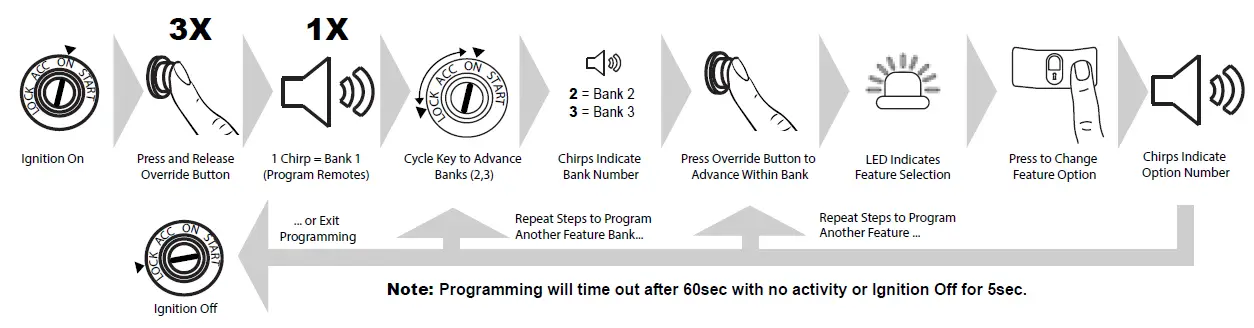
- Turn the ignition ON.
- Press and release the valet/override button 3x.
- The system will beep (1) one time, indicating you have accessed Bank 1.
- Each cycle of the Ignition, OFF/ON, will advance to the next bank (up to Bank 3) then restart at Bank 2. (Note: To reaccess
- Bank 1 for transmitter programming, you will need to exit and re-enter programming mode.)
- The system will beep a number of times to indicate the Bank number:
- 1 beeps: Bank 1 – Programming Remote Controls
- 2 beeps: Bank 2 – Security Control Options
- Once you have accessed the desired bank, press the valet/override button to advance though the features. The LED will flash a number of times to indicate the feature, based on the charts that follow this section. The system will chip a number of times to indicate the Option programmed.
- Once you have accessed the desired feature, press the LOCK button on the remote control to advance though the feature’s setting options. The system will beep a number of times to indicate the Option setting, based on the charts that follow this section.
- Once you have made the desired setting, you can press the valet/override button to advance through the features within the bank, or cycle the Ignition key OFF/ON to advance to the next bank.
- Once you have completed programming, you MUST turn the ignition key to OFF to exit the programming mode. Programming will automatically exit after 60sec of inactivity.
Bank 1: Transmitter Programming Options
| Feature Bank 1 | Description | ||
| CH. | 1 | Auto Program/Lock | Press Lock button on remote |
| 2 | Unlock | Press Unlock button on remote | |
| 3 | Trunk/Start | Press Start button on remote | |
Bank 2: Security Options
| Feature Bank 2 | Options | |||||||
| 1 Chirp | 2 Chirp | 3 Chirp | 4 chirp | 5 Chirp | 6 Chirp | |||
| Features | 1 | Lock / Unlock Function | 500ms | 3.5sec | 500ms L, Dbl UL | DBL L, 500ms UL | DBL L, DBL UL | 500ms L, 350ms UL |
| 2 | Accessory Lock | OFF | ON | |||||
| 3 | Accessory Unlock | OFF | ON | |||||
| 4 | Auto Relock | OFF | Auto Lock | Auto Lock & Arm | ||||
| 5 | Auto Arming | OFF | Auto Arm | Auto Lock & Arm | ||||
| 6 | Parking Light/Trunk Swap | OFF | ON | |||||
| 7 | Silent Choice | OFF | From Transmitter | OEM Style | ||||
| 8 | Exterior Illumination | OFF | With Arm | With Disarm | With Arm & Disarm | |||
Dome Light Delay
To program the Prestige system to wait until the dome light turns off before arming:
- Close all doors.
- With the vehicle ignition off, press LOCK, UNLOCK, LOCK ,UNLOCK, LOCK, UNLOCK, LOCK on the remote control. The dash-mounted LED will turn on.
- Immediately OPEN then CLOSE the door WITHOUT disarming the system. After the dome light turns off, the LED will flash to indicate programming completion.
- Disarm and exit the vehicle.
To return the system to default dome light sensing:
- Turn the vehicle ignition ON then OFF 3 times, then press and hold the valet button for 5 seconds.
- The system will beep 1 time indicating the learned delay has been cleared.
Silent Arm and Disarm
Program the Prestige system to arm and disarm without notification beeps. (The siren will sound if the system is triggered while armed.)
- Turn the ignition ON then OFF.
- Press and release the valet/programming button three (3) times. The system will respond with one (1) beep for ON or two (2) beeps for OFF
User Selectable LED
This feature will control whether the LED is ON or OFF when the system is Armed/Locked. This will be selectable in feature programming OR on-the-fly without entering the programming feature banks.
- Turn the ignition ON, OFF, ON, OFF.
- Press and hold valet button for five (5) seconds. The system will respond with one (1) beep for ON or two (2) beeps for OFF.
Troubleshooting Trigger Zones
Test the doors, hood, trunk, and shock sensor to ensure they trigger the security system. Once triggered, the LED flashes to indicate the trigger source:
| 1 | Shock |
| 2 | Trunk / Hood |
| 3 | Door |
Adjusting the Shock Sensor
- Arm the system, wait 5-10 seconds, then with an open palm carefully apply impact to areas of the vehicle to test the shock sensor’s sensitivity.
- To adjust, turn the adjustment knob on the shock sensor counter-clockwise for less sensitivity; clockwise for more sensitivity.
- If the proper sensitivity still cannot be achieved, re-locate the shock sensor
Wiring Diagrams
Door Lock Connections
Negative-Trigger Door Locks
Verification: The vehicle wires register Ground when the Lock and Unlock switches are activated.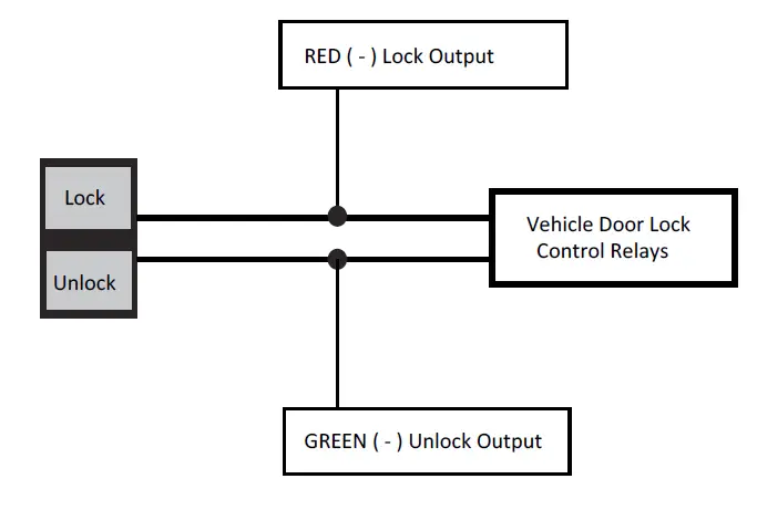
Positive-Trigger Door Locks
Verification: The vehicle wires register 12V+ when the Lock and Unlock switches are activated 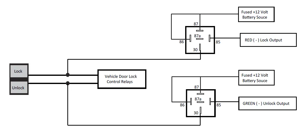
Single-Wire Negative Multiplex Door Locks (Relays required)
Verification: The vehicle wire registers variable Ground values when the Lock and Unlock switches are activated. Please consult the vehicle-specific wire and location chart for resistor values.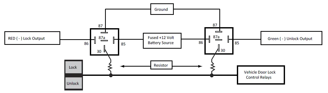
Single-Wire Positive Multiplex Door Locks (Relays required)
Verification: The vehicle wire registers variable 12V+ values when the Lock and Unlock switches are activated. Please consult the vehicle-specific wire and location chart for resistor values.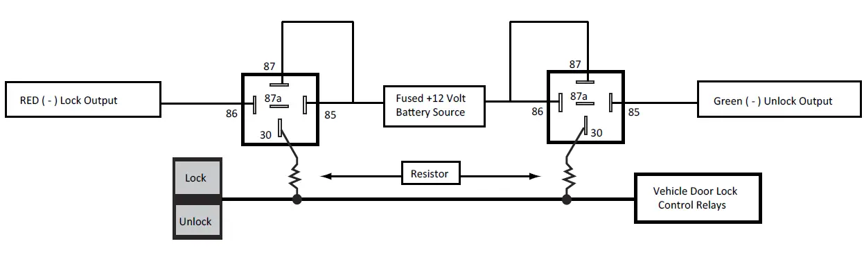
Reverse-Polarity Door Locks (Relays required)
Verification: The vehicle wires rest at Ground and register 12V+ when the Lock and Unlock switches are activated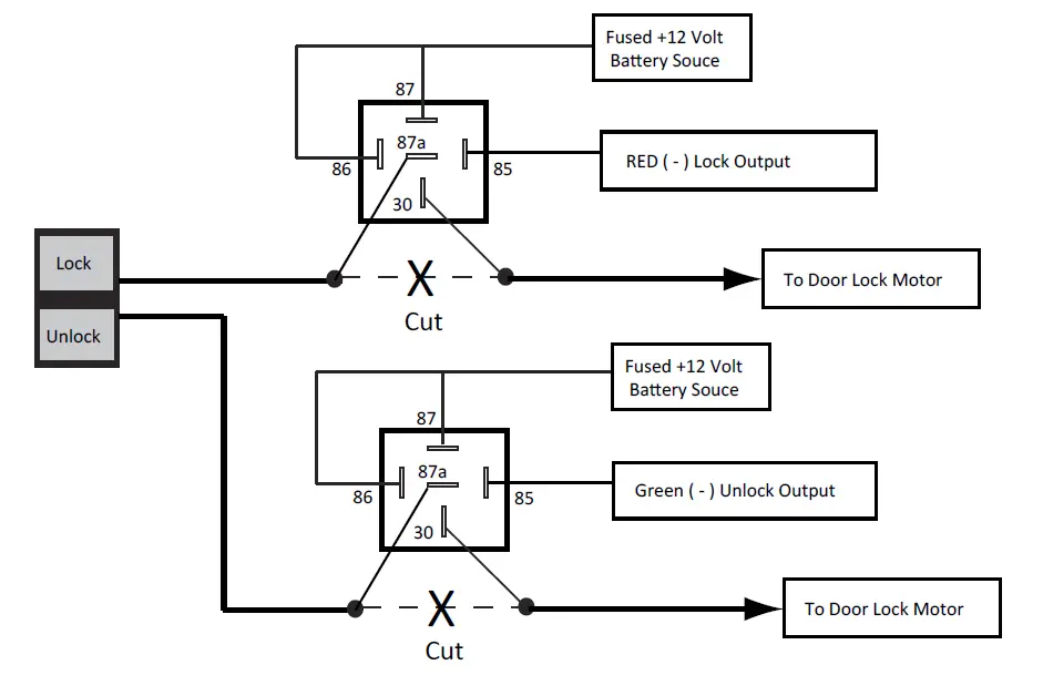
Aftermarket Actuators (Relays and door lock actuators required)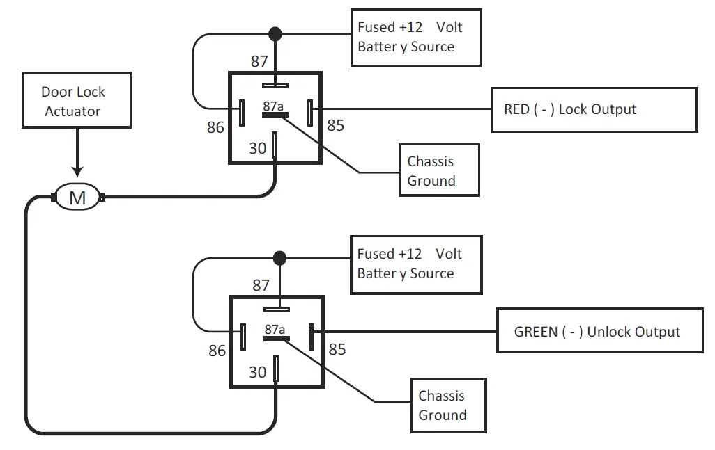
Starter Kill / Anti-Grind Relay Connections
Included Starter Kill / Anti-Grind Relay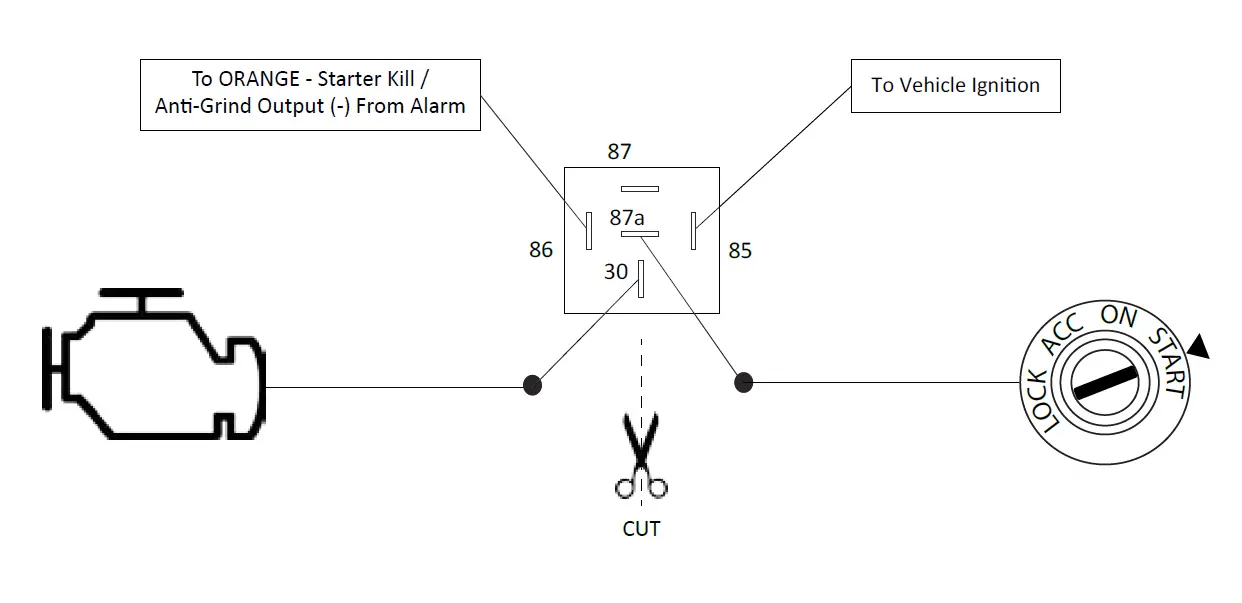
FAQS
Yes it come with installation instructions? i could only find the owners manual on the voxx website
Yes these remotes use code-hopping technologies
Not this model.the aps997z and aps 787z have remote start
These are transmitters. The “brain” must be wired into the vehicle’s wiring harness which takes a knowledge of basic electrical theory and wiring diagrams.
Yes you can hook the alarm wires to the horn instead of the alarm
Any alarm fits most cars. Its really a question of the installation. If you have never done a car alarm before, I would suggest professional installation.
According to manufacturer you have to program the alarm to recognize when the light shuts down but im still working a how to use that feature on ford since ford wiring is different that most conventional cars
No it have to flashed to curtain car make and models
No Will this work woth my factory remotes
Yes this unit be hooked up to open drivers door with one click and the other doors on second click
The parking light will flash as you activate the door locks, otherwise no.
To enter the valet mode: From the disarmed condition, turn the ignition switch to the “on” position. Press and hold the valet push-button switch until the dash mounted LED turns on. To return to the normal mode of operation, press and release the valet switch any time the ignition is on.
Locking and unlocking the driver’s side door can reset the switch and cause the alarm to cease. If the driver’s side door doesn’t work, try the passenger door. Further, try turning your vehicle on as well
You can turn off or power down your home alarm system by disconnecting its backup battery and then unplugging the transformer for the device from the wall outlet. You can confirm that the panel has been powered down by checking its touchscreen or keypad and making sure that it is blank
The Tesla Model S is touted as one of the most secure vehicles because of its anti-theft features. Tesla owners can monitor where their car is right from their smartphone. Even if the thief was able to hack into the system to disconnect the tracker, Tesla would be alerted immediately.


