BEIJER REF CUBO2Smart Lincoln Coop gets Smart Instruction Manual
INSTALLATION INSTRUCTIONS
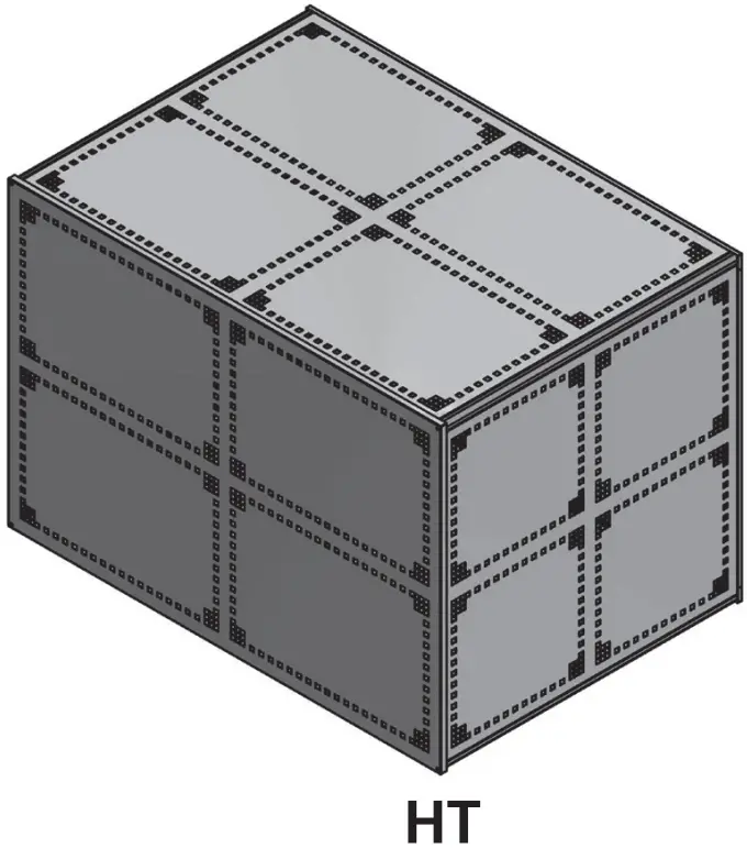
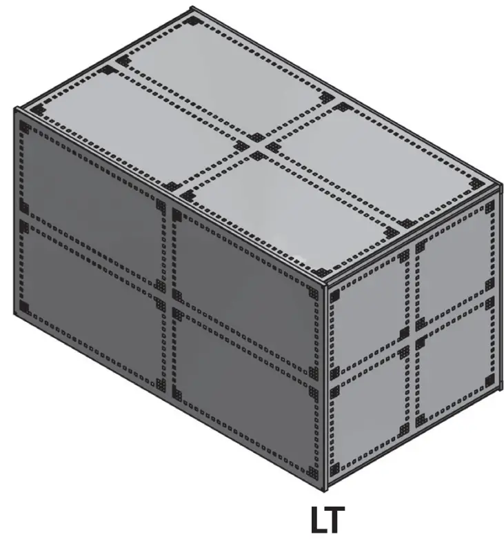
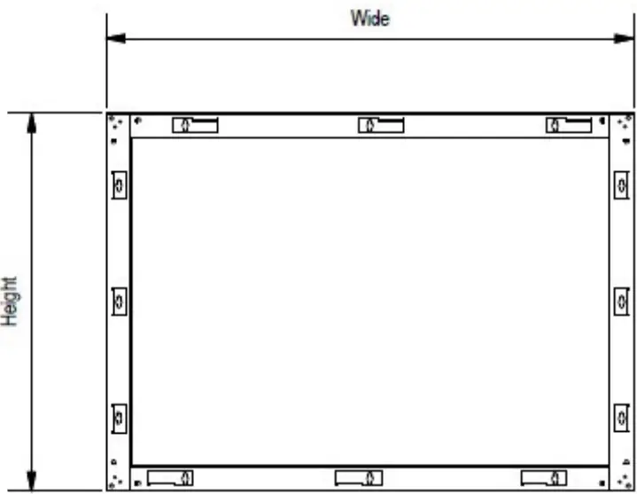
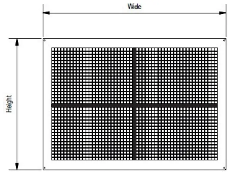
DIMENSIONS
|
Description | External | Internal | Guard weight | |||||
| Height | Width | Depth | Height | Width | Depth | |||
677048 | CCG3002/CUBO – CUBO2Smart LT cage | 1150mm | 2000mm | 1150mm | 1120mm | 1970mm | 1120mm | 80kg |
677049 | CCG3001/CUBO – CUBO2Smart HT cage | 1150mm | 1650mm | 1150mm | 1120mm | 1620mm | 1120mm | 60kg |
COMPONENTS
- A : Mounting Frame x 1 Nos

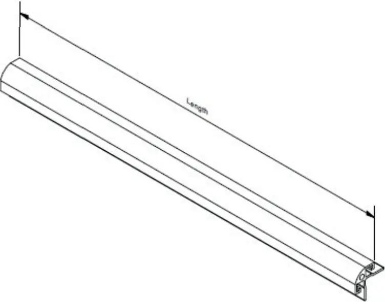
- B : Aluminium Arm x 4 Nos

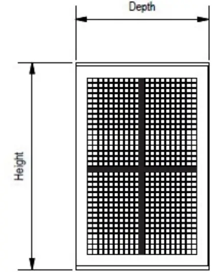
- C : End Panel x 2 Nos

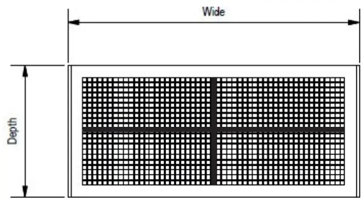
- D : Top Panel x 1 Nos

- E : Front/Rear or Side Panel (depending on installation method) x 1 Nos

- F : Floor Mounting Feet x 4 Nos


NB The required components are dependent on the installation method; not all components are required for all methods
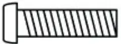
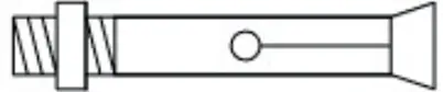
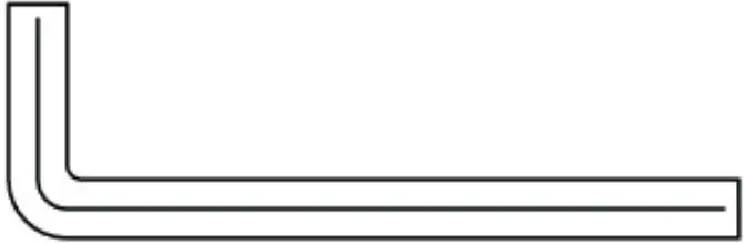
FIXINGS
- F : M8 x 20mm Hexagonal Headed Bolt x 8

- G : Spring Washer x 4

- H : Wall Anchor Bolt x 4

- I : Hexagonal Key x 1


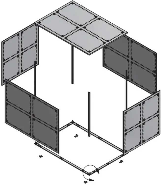
FLOOR STANDING UNIT INSTALLATION INSTRUCTIONS – OPTION 1
- Using 4 x hexagonal headed bolts and 4 x spring washers, bolt the arms to the wall mount / floor mount frame.
- Using the fixings provided, secure the floor mounted fixing feet to the frame.
- Using the anchor bolts provided, if suitable, secure the frame and feet assembly to the floor surface.
- Carefully slide the end panels within the arms into position on the frame assembly.
- Carefully slide the side panels within the arms into position on the frame assembly.
- Using 4 x hexagonal headed bolts provided, secure the top panel to the guard assembly.

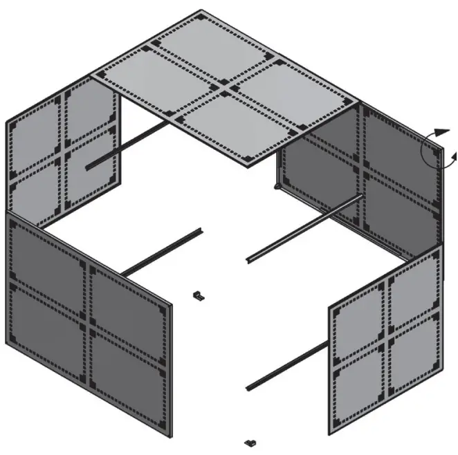
FLOOR STANDING UNIT INSTALLATION INSTRUCTIONS – OPTION 2
- Using 4 x hexagonal headed bolts and 4 x spring washers, bolt the arms to the rear panel.
- Using the fixings provided, secure the floor mounted fixing feet to the underside of the arms closest to the floor.
- Using the anchor bolts provided, if suitable, secure the rear panel, arm and feet of the guard assembly to the floor surface.
- Carefully slide the end panels within the arms into position on the guard assembly.
- Carefully slide the top panel within the arms into position on the guard assembly.
- Using 4 x hexagonal headed bolts provided, secure the front panel to the guard assembly.

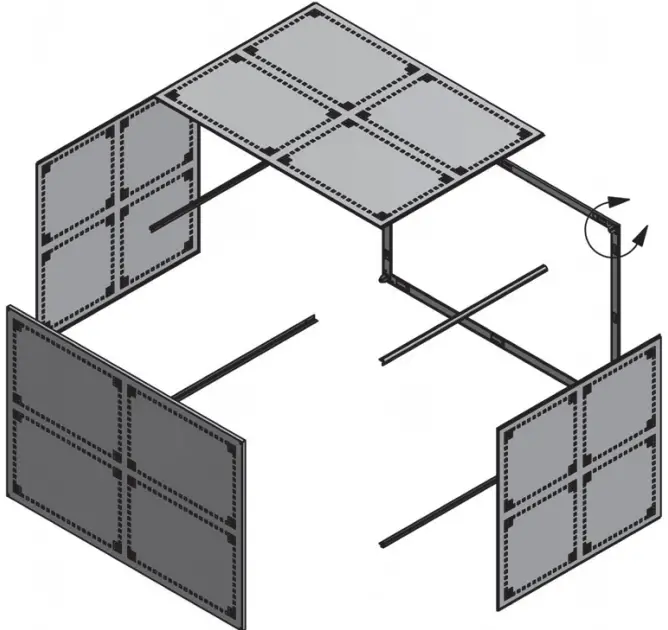
WALL MOUNTED UNIT INSTALLATION INSTRUCTIONS
- Using 4 x hexagonal headed bolts and 4 x spring washers, bolt the arms to the wall frame.
- Using the wall fixings bolts if suitable, secure the wall frame to the wall.
- Carefully slide the side panels within the arms into position on the frame assembly.
- Carefully slide the top panel within the arms into position on the frame assembly.
- Using 4 x hexagonal headed bolts provided, secure the front panel to the guard assembly
NB The extra panel and floor mounted fixing feet provided will not be needed for this type of installation.
HIGH WALL MOUNTED UNITS
For high wall mounted unit installations slide the extra panel into position at the bottom of the cage assembly prior to fitting the front panel as detailed within instruction 5 above.
NB The floor mounted fixing feet provided will not be needed for this type of installation.
Information correct at time of going to press


