light emotion PARBAR4 QUAD User Manual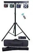
Introduction
Thank you for your patronage. We are confident that our excellent products and service can satisfy you. For your own safety, please read this user manual carefully before installing the device.
In order to install , operate, and maintain the lighting safety and correctly. We suggest that the installation and operation should be done by the verified technician and follow the instruction strictly.
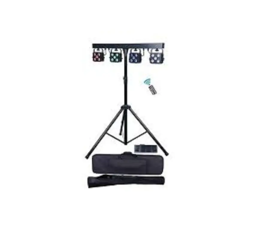
Following spare parts are included with the fixture:
- One PARBAR QUAD light
- One T-stand
- One wireless foot controller
- One remote controller
- One use manual
- One power cable
Caution
Before leaving the factory, this device has passed strict inspection, functions stable and perfect packing. If this device will be operated in any way different to the one described in this manual, the product may suffer damages and the guarantee becomes void. Furthermore, any other operation may lead to dangers like short circuit, burns, electric shock, crash etc. If any technology changes of this manual, company do not notice in further and have interpretation.
CAUTION!
 Keep this device away from rain and moisture!
 Unplug mains lead before opening the housing!
![]() Warning!
Warning!
Damages caused by the disregard of this user manual are not subject to warranty. The dealer will not accept liability for any resulting defects or problems.
Symbol Instruction On The Device
 CE Compliant
 Suitable directly installed on the common combustible materials devices
 Only indoor use
 Environmental protection
- T
 he minimum distance from fixture to the lighted objects(meter)
Safety Instructions
CAUTION!
Be careful with your operations. With a dangerous voltage you will suffer a dangerous electric shock when touching wires!
This device has left the factory in perfect condition. In order to maintain this condition and to ensure a safe operation, it is absolutely necessary for the user to follow the safety instructions and warning notes written in this user manual.
- If the device has been exposed to temperature changes due to environmental changes, do not switch it on intermediately. The arising condensation could damage the device. Leave the device switched off until it has reached room temperature.
- Please make sure that the device be earthed.
- Please replace housing if it is broken. This fixture can be used after finished
installed. - The electric connection must carry out by qualified person.
- Make sure that the available voltage is not higher than stated at the end of this manual.
- Make sure the power cord is never crimped or damaged by sharp edges. If this would be the case, replacement of the cable must be done by an authorized dealer.
- If the external flexible cable or cord of this fixture is damaged, it shall be exclusively replaced by the manufacturer or his service agent or a similar qualified person in order to avoid a hazard.
- Please turn off the fixture if don’t use in the fixture or want to clean, maintenance.
CAUTION!
- Never touch the device during operation The housing may heat up
- Never look directly into the light source, as sensitive persons may suffer an epileptic shock.
Please be aware that damages caused by manual modifications to the device are not subject to warranty. Keep away from non-professionals.
General Guidelines
- This device is a lighting effect for professional use on stages, in discotheques, theaters, etc., the device was designed for indoor use only.
- This fixture is only allowed to be operated with the max alternating current which stated in the technical specifications in the last page of this manual.
- The device can work continuous y for eight hours. Lighting effects are not designed for permanent operation. Consistent operation breaks may ensure that the device will serve you for a long time without defects.
- Handle with care, do not make the device by strong shocks.
- While choosing the installation-spot, please make sure that the device is not exposed to extreme heat, moisture or dust. Please don’t project the beam onto combustible substances.The minimum distance between light-output from the projector and the illuminated surface must be more than I meter.
- Please do not in damp, overheat or dusty environment install and use the device. Do not use light on fuel. The distance between the device and the projectile to keep at least 1 meter
- If you use the quick lock cam in hanging up the fixture, please make sure the quick lock fasteners turned in the quick lock holes correctly,and add satiety rope.
- Operate the device on! y after having familiarized with its functions. Do not permit operation by persons not qualified for operating the device. Most damages are the result of unprofessional operation.
- Please use the original packaging if the device is to be transported.
- For safety reasons, please be aware that all modifications on the device are forbidden.
- Any installation and maintenance must by professional person.
- If this device will be operated in any way different to the one described in this manual, the product may suffer damages and the guarantee becomes void. Further more, any other operation may lead to short-circuit, burns, electric shock, lamp explosion, crash, etc.
Installation instruction
CAUTION!
Please consider the GB7000.15IEN60598-2-17 and the other respective national norms during The installation. The installation must only be carried out by a qualified person.
- The applicable temperature for the lighting is between -25°C to 45°C. Do not use the lighting under or above the temperature.
- The installation of the effect has to be built and constructed in a way that it can hold 10 times the weight for I hour without any harming defoliation.
- The installation must always be secured with a secondary safety attachment, e.g. an appropriate safety rope. Never stand directly below the device when mounting, removing or servicing the fixture.
- The operator has to make sure the safety relating and machine technical installations are approved by an expert before taking the device into operation for the first time.
- These installations have to be approved by a skilled person once a year.
- Overhead mounting requires extensive experience, including among others calculating working load limits, installation material being used, and periodic safety inspection of all installation material and the device. If you lack these qualifications, do not attempt the installation yourself. Improper installation can result in bodily injury.
Specification of the Device
4pcs 5*IOW RGBW 4inl LED with average 50000 hours lifespan;
- beam angle : 15″; 3-pins XLR Each par bar can separately control
- Single par can at 3m (light spot is l.lm) : Red: 210Iux/Green: 5901ux/
Blue: 701ux/ White: 480luxl RGBW:690Iux - 4pcs par can full on at 3m(light spot is 2.lm): Red:685luxlGreen: 1870lux
Blue: I 651ux/ White: 1400luxl RGBW: 2300lux - Product size(without stand): 100*12*24cm T-Stand: l.2m–3m adjust. can loading max 50Kg
- Wireless foot controller: 12V 23A, the farest 30m available control(please let wireless foot controller on OFF if not using it, for protect battery and won’t be current consuming.)
- Packing : carry case
- Packing case size : 108*3\.5* 15cm
- Packing T-Stand bag size : 126* 14* 15cm
- G. W: 17.8Kg (all of in one outer carton, including Ipcs light bag and Ipcs stand bag)
Menu operation
| ID | Display | Range | Default value | Function |
| 1 | Addr | A001-A512 | A001 | DMX5 12 |
| 2 | ChAn | 05ch | 20ch | 5 DMX channel |
| 08ch | 8 DMX channel | |||
| 20ch | 20 DMX channel | |||
| 3 | CoLo | r000-r255 | 0 | Manual color option. Red dimmer |
| G000-G255 | 0 | Manual color option, Green dimmer | ||
| b000-b255 | 0 | Manual color option, Blue dimmer | ||
| v000-v255 | 0 | Manual color option, White dimmer | ||
| FL00-FL99 | 0 | Strobe from slow to fast | ||
| 4 | Auto | Pr01-Pr08 | Pr0l | Auto mode |
| 5 | SP70 | SP00-SP99 | 70 | Chasing speed |
| 6 | BLAC | ON | OFF | Black-out On |
| OFF | Black-out OIT | |||
| 7 | Hold | ON | OFF | Hold On |
| OFF | Hold Oif | |||
| 8 | Soun | ON/OFF | OFF | Sound On/Off |
| 9 | SEnS | SEO I-SE99 | 70 | Sound sensitivity |
| 10 | CG99 | 01-99 | 99 | Color gradual change |
| 11 | CJ99 | 01-99 | 0 | Color jump change |
| 12 | Sind | Host | SLAV | Master mode |
| SLAV | Slave mode | |||
| 13 | Foot | ON/OFF | OFF | Wireless foot controller ON/OFF |
| 14 | LED | ON/OFF | ON | LED display(led display black-out after l3sec without click) |
| 15 | Deft | yes | Factory default | |
| 16 | U1.00 | Ul.00 | Software version |
Remote Control
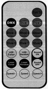
| ID | DISPLAY | Function |
| 1 | Stand By | Power On/Oft |
| 2 | DMX | Hold |
| 3 | Show 1 | Show 1 |
| 4 | Show 2 | Show 2 |
| 5 | Show 3 | Show 3 |
| 6 | Show 4 | Show 4 |
| 7 | Show 5 | Show 5 |
| 8 | Show 6 | Show 6 |
| 9 | Show 7 | Show 7 |
| 10 | Show 8 | Show 8 |
| 11 | Led Color | LED color Jump |
| 12 | LED Random | LED Color gradual change |
| 13 | Sound on | Sound on |
| 14 | Laser color | Hold |
| 15 | Laser Random | Hold |
| 16 | Laser Random | Sound off |
| 17 | Speed- | Show1-show8 speed increase |
| 18 | Speed | S1iow1-show8 speed in middle(default) |
| 19 | Speed+ | Showl-show8 speed decrease |
Wireless foot controller
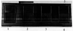
| ID | Silkscreen | Function |
| 1 | BLACK | Black mode |
| 2 | AUTO | Auto mode |
| 3 | COLOR | Color mode |
| 4 | MUSIC | Sound mode |
| 5 | ON/OFF | Power On/Off |
Note: please let wireless foot controller on OFF If not using it, for protect battery
and won’t be current consuming.
DMX table
5CH Mode
| Channel | Value | Function | |
| 1CH | Total dimmer | 0-255 | Total dimmer |
| 2CH | Red dimmer | 0-255 | Red dimming |
| 3CH | Green dimmer | 0-255 | Green dimming |
| 4CH | Blue dimmer | 0-255 | Blue dimming |
| 5CH | White dimmer | 0-255 | White dimming |
8CH Mode
| Channel | Value | Function | |
| ICH | Total dimmer | 0-255 | Total dimmer |
| 2CH | Strobe | 0-255 | Strobe from slow to fast |
| 3CH | Red dimmer | 0-255 | Red dimming |
| 4CH | Green dimmer | 0-255 | Green dimming |
| 5CH | Blue dimmer | 0-255 | Blue dimming |
| 6CH | White dimmer | 0-255 | White dimming |
| 7CH | Show mode | 0-9 | No function |
| 10-99 | Color option | ||
| 100- 129 | Jumping | ||
| 130-159 | Gradual change | ||
| 160-189 | Chasing | ||
| 190-219 | Sound 1(Gradual +chasing) | ||
| 220-249 | Sound 2( Jumping) | ||
| 250-255 | Sound 3 (Chasing) | ||
| 8CH | Speed | 0-255 | Speed from slow to fast |
20CH Mode
| Channel | Value | Function | |
| 1CH | Total dimmer | 0-255 | Total dimmer |
| 2CH | Strobe | 0-255 | Strobe from slow to lâst |
| 3CH | R1 dimmer | 0-255 | Red1 dimming |
| 4CH | GI dimmer | 0-255 | Green 1 dimming |
| SCH | B1 dimmer | 0-255 | Blue I dine ining |
| 6CH | W1 dimmer | 0-255 | White 1 dimming |
| 7CH | R2 dimmer | 0-255 | Red2 dining ing |
| 8CH | G2 dimmer | 0-255 | Green2 dimming |
| 9CH | B2 dimmer | 0-255 | Blue2 dimming |
| IOCH | W2 dimmer | 0-235 | White2 dimming |
| 11CH | R3 dimmer | 0-255 | Red3 dimming |
| I2CH | G3 dimmer | 0-255 | Grcen3 dimniine |
| l3C H | B3 dimmer | 0-255 | Blue3 dinini ing |
| l4CH | W3 dimmer | 0-255 | White3 dimming |
| l 5C H | R4 dimmer | 0-255 | Red4 dimming |
| I6CH | G4 dimmer | 0-255 | Green4 dimming |
| I7CH | B4 dimmer | 0-235 | Blue4 dimming |
| 18CH | W4 dimmer | 0-255 | White4 dimming |
| l9CH | Show mode | 0-9 | No function |
| 10-99 | Color option | ||
| 100-129 | Jumping | ||
| 130-159 | Gradual change | ||
| 160-189 | Chasing | ||
| 190-219 | Sound 1 (Gradual +cliasing) | ||
| 220-249 | Sound 2( Jumping) | ||
| 250-255 | Sound 3 (Chasing) | ||
| 20CH | Speed | 0-255 | Speed from slow to fast |
DMX-512 control connection
Connect the provided XLR cable to the male 3-pin XLR output of your controller and the other side to the female 3-pin XLR input of the light.You can chain multiple lights together through serial linking. the signal cable should have two core with shielded cable, the signal connectors are with XLR input and output connectors. Please refer to the below diagram:
- DMX output

- DMX Input

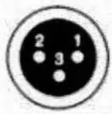
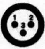
- Ground
- Signal ( -_
- Signal ( + )
DMX address setting
Each fixture must set a specific starting address. When receiving signal, fixture will receive channel control signals of this address from the DMX controller. For easy to use. the user can set the same address for several fixtures , also can set up a unique address for every device. If you set the same address for all fixtures, all the fixtures will receive from the same DMX channels signal. All connecting fixtures are jointly controlled, controller can’t separate control a device. If you set a different address for each fixture, each fixture will receive unique signal and can be controlled by DMX controller separately. This fixture has 20 channels. you should set the starting address of the first limit to I, the second unit to 21 (1 * 20 + I), the third unit to 41 (2 *20+ I), and so on.
DMX-S12 connection with DMX terminator
Ifthere are many lines or lights, it is recommended to use a DMX terminator to prevent DMX signal corruption, the DMX tenninator is an simple XLR plug with a 120 n resistor connected between pins 2 and 3,which is then plugged into the output XLR socket of the last fixture in the chain.

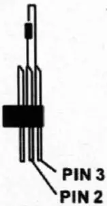
Welding a 120 ohm resistor between 2 and 3 pins male XLR , and insert it into the signal output of the last device.
Cleaning and maintenance
The following points have to be considered during the inspection:
- All screws of the device have to be tightly connected and must not be corroded.
- There must not be any deformation on housings, fixations and installation spots( ceiling, suspension,trussing).
- Mechanically moving parts like axles,eyes and others must not show any traces of wearing (eg: material abrading or damages land must not rotate with unbalances.
- The electric power supply cables must not show any damages,material fatigue(eg: porous cables) or sediments.
- Please use wet cloth to clean the housing. Glass cleaning liquid is suitable, never use alcohol or solvents!
Further instructions have to be adhered by a skilled installer to prevent any safety problems.
The cooling-fan should be cleaned monthly. The interior of the fixture should be cleaned at least annually using a vacuum-cleaner or an air-jet.
There are no serviceable parts inside the device. Maintenance and service operations are only to be carried out by authorized dealers.
Warranty Card
This product is made of high-brightness transistor. We will provide 1 year warranty under the condition that user has operated the light normally and lifetime service. We won’t provide warranty if the damage is caused by artificial or force majeure event. Cost of fittings should be charged by user if product need maintenance after 1 year .Please cut this warranty card and shipped it along with the product to our factory when applying for warranty.
| Product: | |
| Warranty date: From | |
| User’s name: | |
| Company: | |
| Purchasing date: | |
| To | |
| Add: | |
| Tel : | |
| Code of invoice: |


