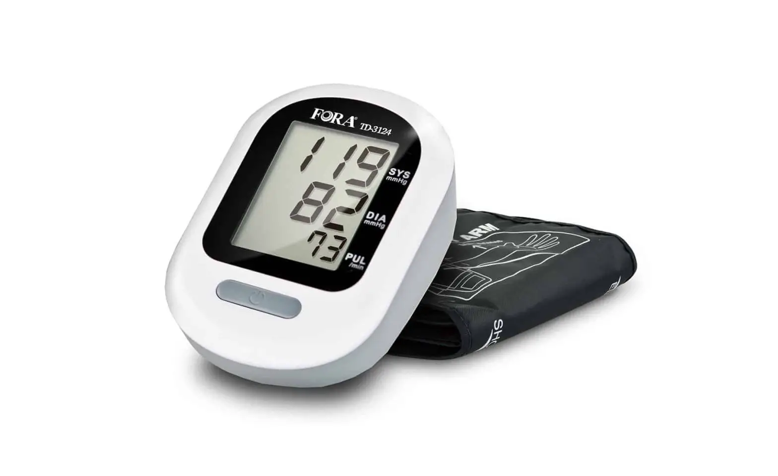
FORA TD-3124B Blood Pressure Monitoring System Owner’s Manual
Dear System Owner:
Thank you for purchasing the FORA Vital Blood Pressure Monitoring System. This manual provides important information to help you operate this system properly. Before using this product, please read the following contents thoroughly and carefully.
With the compact size and easy operation of this FORA Vital Blood Pressure Monitoring System, you can easily monitor your blood pressure by yourself at any time or place. In addition, this system can help you and your healthcare professionals to monitor and adjust your treatment plans, and keep your blood pressure under control.
If you have other questions regarding this product, please contact the place of purchase.
IMPORTANT SAFETY PRECAUTIONS
READ BEFORE USE
- Use this device ONLY for the intended use described in this manual.
- Do NOT use accessories which are not specified by the manufacturer.
- Do NOT use the device if it is not working properly or damaged.
- Do NOT use under any circumstances on newborns or infants.
- This device does NOT serve as a cure for any symptoms or diseases. The data measured are for reference only. Always consult your doctor to have the results interpreted.
- Keep the equipment and its flexible cord away from hot surfaces.
- Do NOT apply the cuff to areas other than the place directed.
- Use of this instrument in a dry environment, especially if synthetic materials are present (synthetic clothing, carpets etc.) may cause damaging static discharges that may cause erroneous results.
- Do not use this instrument in close proximity to sources of strong electromagnetic radiation, as these may interfere with the accurate operation.
- If you experience any serious incident that occurred in relation to the use of this product, please report it to the manufacturer and the competent authority of medical devices in your country.
A serious incident means any incident that directly or indirectly led, might have led, or might lead to any of the following:- the death of a patient, user, or other people,
- the temporary or permanent serious deterioration of a patient’s, user’s or other person’s state of health,
- A serious public health threat.
KEEP THESE INSTRUCTIONS IN A SAFE PLACE
BEFORE YOU BEGIN
Intended Use
The FORA Vital system is a system designed to measure blood pressure non-invasively. It is intended for use at home and in clinical settings. The device is not to be used for the diagnosis or screening of hypertension or for testing on newborns.
Test Principle
Blood pressure is measured non-invasively at the arm based on oscillometric method.
This device is NOT able to take measurements in the presence of common arrhythmia, such as atrial or ventricular premature beats or atrial fibrillation. It may produce reading error.
Meter Overview
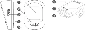
- Display Screen
- ON/OFF Button
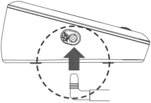
To start a single NIBP measurement (NIBP: Non invasive blood pressure) - Air jack
- DC Adapter Port Connect to a power supply
- M Button
- Enter the meter memory
- Pressure Cuff
- Air Tube
- Air Plug Connect to air jack
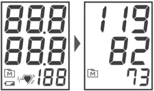
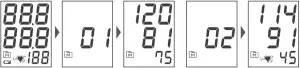
Display Screen
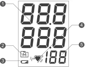
- Test Result
- Memory Mode Symbol
- Low Battery Symbol
- Pulse Rate Symbol
- Pulse Rate
TESTING YOUR BLOOD PRESSURE
Before Measurement
- Avoid caffeine, tea, alcohol and tobacco for at least 30 minutes before measurement.
- Wait 30 minutes after exercising or bathing before measurement.
- Sit or lie down for at least 10 minutes before measurement.
- Do not measure when feeling anxious or tense.
- Take a 5-10 minute break between measurements. This break can be longer if necessary, depending on your physical condition.
- Keep the records for your doctor as reference.
- Blood pressure naturally varies between each arm. Always measure your blood pressure on the same arm.
Fitting the Cuff Properly
- Connect the air plug of the tubing to the air jack of the meter.

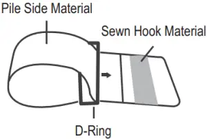
- Assemble the cuff as shown on the right. The smooth surface should be inside of the cuff loop and the metal D-ring should not touch your skin.

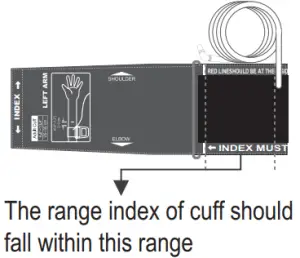
- Stretch your left (right) arm in front of you with your palm facing up. Slide and place the cuff onto your arm to let the air tube and artery mark region (in red) toward the lower arm. Wrap and tighten the cuff above your elbow. The red line on the edge of the cuff should be approximately 2 cm to 3 cm (0.8” to 1.2”) above your elbow. Align the tube over the main arteries on the inside.

- Leave a little free space between the arm and the cuff; you should be able to fit two fingers between them. Clothing must not restrict the arm. Remove all clothing covering or constricting the measurement arm.

- Press the hook material firmly against the pile material. The top and bottom edges of the cuff should be tightened evenly around your upper arm.

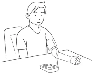
Proper Measurement Position
- Sit down for at least 10 minutes before measuring.
- Place your elbow on a flat surface. Relax your hand with the palm facing up.
- Make sure the cuff is about the same height as the location of your heart. Press . Remain still and do not talk or move during the measurement.
WARNING:
If the cuff is relatively lower (higher) than the heart, the obtained blood pressure value could be higher (lower) than the actual value. A 15 cm difference in height may result in an error around 10 mmHg. - Measurement is in progress.
After the meter is turned on, the cuff will begin to inflate automatically.
TAKING MEASUREMENTS
Always apply the pressure cuff before turning on the
meter.
- Press
 . All the LCD symbols and the last blood pressure result will appear. Then the cuff will begin to inflate automatically.
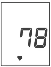
- The heart symbol “ ” will flash when pulse is detected during the inflation.

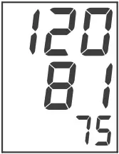
- After the measurement, the meter displays the systolic pressure, diastolic pressure and pulse rate.

- Press to switch off. Or it will switch off automatically after being idle for 3 minutes.
WARNING:
- If you press during measurement, the monitor will be turned off.
- If the pulse rate symbol is shown as “
 ” instead of “ ”, this indicates that the meter has detected an irregular heartbeat.
MONITOR MEMORY
Your meter stores the 100 most recent blood pressure test results in the meter memory. To recall the memory, start with the meter off.
Reviewing Test Results
- .Press and release
 . will appear on the display. Press again, and the first reading you see is the last test result.
 - Press to recall the next test results stored in the meter each time you press.
- Exit the memory. Keep pressing and the meter will turn off.

NOTE:
- To delete ALL the results, press and firmly holds for 4 seconds until “dEL” displays.
- Releases , “CLr ALL” and “
 “ are displayed on the meter, which indicates that all results have been deleted.
 - Any time you wish to exit the memory, presss or leave it without any action for 3 minutes. The meter will switch off automatically.
- If using the meter for the first time, you will only see the “ “ symbol on the display when you recall the test results. It indicates that there is no test result in the memory.
MAINTENANCE
Battery
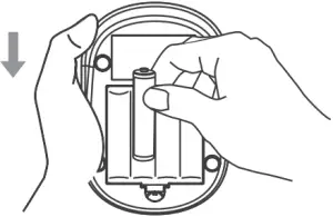
Your meter comes with four (4) 1.5V AA size alkaline batteries.
Low Battery Signal
The symbol appears with E-b: The power is not enough to do a test. You must change the batteries immediately.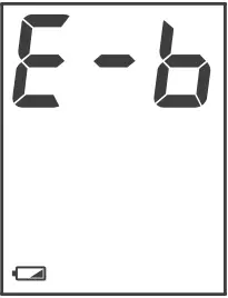
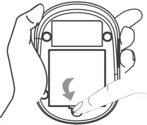
Replacing the Battery
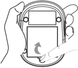
To replace the batteries, make sure the meter is turned off.
- Press the edge of the battery cover and lift it up to remove.

- Remove the old batteries and replace with four 1.5V AA size alkaline batteries.

- Close the battery cover. If the batteries are inserted correctly, you will hear a “beep” afterwards.

NOTE:
- Replacing the batteries does not affect the test results stored in memory.
- As with all small batteries, these batteries should be kept away from small children. If swallowed, promptly seek medical assistance.
- Batteries might leak chemicals if unused for a long time. Remove the batteries if you are not going to use the device for an extended period (i.e., 3 months or more).
- Properly dispose of the batteries according to your local environmental regulations.
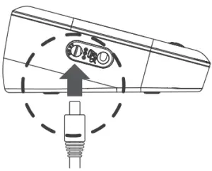
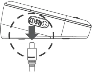
USING AC ADAPTER
Connect AC Adapter to the Meter
- Connect the AC adapter plug to the DC adapter jack of the meter.

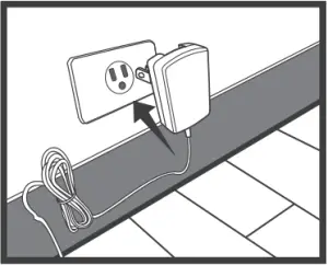
- Plug the AC adapter power plug into an electrical outlet. Press ON/OFF to start the measurement.

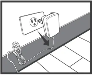
Remove the AC Adapter from the Meter
- When the meter is off, remove AC adapter power plug from the electrical outlet.

- Disconnect the AC adapter plug from the DC adapter jack of the monitor.

CARING FOR YOUR METER
To avoid the meter from dirt, dust or other contaminants, wash and dry your hands thoroughly before use.
Cleaning
- To clean the meter exterior, wipe it with a cloth moistened with tap water or a mild cleaning agent, and then dry the device with a soft dry cloth. Do NOT flush with water.
- Do NOT use organic solvents to clean the meter.
- Do NOT wash the pressure cuff.
- Do NOT iron the pressure cuff.
Meter Storage
- Storage condition: -20°C to 70°C (-4°F to 158°F), between 10% to 95% relative humidity.
- Always store or transport the meter in its original storage case.
- Avoid dropping or heavy impact.
- Avoid direct sunlight and high humidity.
DETAILED INFORMATION
Reference Values
Clinical studies show that adult diabetes is often accompanied by elevated blood pressure. People with diabetes can reduce their heart risk by managing their blood pressure along with diabetes treatment*4. Monitoring your routine blood pressure trend helps you to know your body condition. Human blood pressure naturally increases after reaching middle age.
The recommended blood pressure range is as below:
| Classification | Systolic Pressure (mmHg) | Diastolic Pressure (mmHg) |
| Hypotension | Less than 90 | Less than 60 |
| Normal | Less than 120 | Less than 80 |
| Pre-hyperten- sion | 120 – 139 | 80 – 89 |
| Stage 1 Hyper- tension | 140 – 159 | 90 – 99 |
| Stage 2 Hyper- tension | 160 or more | 100 or more |
- National Heart, Lung, and Blood Institute, Diseases and Conditions
- The Seventh Report of the Joint National Committee on Prevention, Detection, Evaluation, and Treatment of High Blood Pressure. NIH Publication. 2003. No. 03-5233
- American Diabetes Association: The Diabetes Heart Disease Link Surveying Attitudes.
SYSTEM TROUBLESHOOTING
If you follow the recommended action but the problem persists, or error messages other than the ones below appear, please call your local customer service. Do not attempt to repair by yourself and never try to disassemble the monitor under any circumstances.
Error Messages
MESSAGE | CAUSE | WHAT TO DO |
E-1 | Inflation or pressure error. | Please contact local customer service for help. |
E-4 | Blood pressure measurement error. | Refit cuff tightly and correctly.Relax and repeat the measurement. If error still remains, contact local customer service for help. |
E-b | Batteries are dead. | Replace the batteries. |
E-A | Problems with the meter. | Review the instructions and repeat the test. If the meter still does not work, please contact the local customer service for help. |
E-E |
Troubleshooting
- If no display appears after pressing :
POSSIBLE CAUSE
WHAT TO DO
Batteries exhausted. Replace the batteries. Batteries incorrectly installed or absent. Check if the batteries are correctly installed. - If the heart rate is higher/lower than user’s average:
POSSIBLE CAUSE
WHAT TO DO
Movement during measurement. Repeat the measurement. Batteries incorrectly installed or absent. Rest at least 30 minutes before repeating the measurement. - If the result is higher/lower than the user’s average measurement:
POSSIBLE CAUSE
WHAT TO DO
User may not be in the correct position while measuring. Adjust to the correct position for measurement. Blood pressure naturally varies from time to time. Keep in mind for the next measurement. - If the cuff inflates again while measuring:
POSSIBLE CAUSE
WHAT TO DO
Cuff is not fastened. Fasten the cuff again. If user’s blood pressure is higher than the pressure the device has inflated, the device will automatically increase the pressure and start to inflate again. Stay relaxed and wait for the measurement.
SYMBOL INFORMATION
| Symbol | Referent | Symbol | Referent |
| Consult instructions for use |  | Storage / transport temperature limitation | |
 | Type BF applied part |  | CE Mark |
 | Storage / transport humidity limitation |  | Manufacturer |
| Medical device | Battery | ||
| Serial number | Model No. | ||
| Authorised representative in the European Union | Ingress protection rating | ||
 | Dispose of or recycle the electrical wastes according to local regulations |  | Caution, consult accompanying documents |
SPECIFICATIONS
System performance
- Power source: Four 1.5V AA alkaline batteries
- Size of monitor w/o cuff: 130.5 mm (L) x 90 mm (W) x 55 mm (H), 210 g without batteries.
- Cuff Size: 24-43 cm (9.4-16.9 inches) with air tube 100 cm
- Memory: Maximum 100 memory records
- Power saving: Automatic power off if system idle for 3 minutes
- System operating conditions: 5°C to 40°C (41°F to 104°F), between 15% – 93%
- RH Meter storage conditions: -25°C to 70°C (-13°F to 158°F), between 10% – 95%
- RH Power Supply Input: four (4)1.5V AA size alkaline batteries DC +6V / 1A (max) via Power Plug.
Blood pressure measurement performance
- Pressure range: 0 – 300 mmHg
- Measurement unit: mmHg
- Systolic Measurement Range: 60 mmHg -255 mmHg
- Diastolic Measurement Range: 30 mmHg -195 mmHg
- Pulse Rate Measurement Range: 40 -199 beats / minute
- Maximum inflation pressure: 280 mmHg
- Accuracy of Pressure: ±3 mmHg or ±2% of reading
- Accuracy of Pulse rate: ±4% of reading
- Heart rate range: 40 – 199 beat per minute
This device has been tested to meet the electrical and safety requirements of: IEC/EN 60601-1, IEC/EN 60601-1-2.
Reference to Standards:
- EN 1060-1 /-3, NIBP-requirements
- IEC60601-1 General requirement for safety
- IEC60601-1-2 Requirements for EMC
- EN1060-4, NIBP clinical investigation
- AAMI / ANSI / IEC 80601-2-30, ANSI/AAMI/ISO 81060-2, NIBP requirements
TERMS & CONDITIONS OF WARRANTY
- We warrant this product to be free of defects in workmanship and materials within the said warranty period on the warranty certificate.
- During the warranty period, if this product is found to be defective, you may bring it, together with the purchase receipt and Warranty Certificate, on a carry-in basis to our office during normal business hours for warranty service. We will then repair or replace defective parts or exchanging the whole product as we may choose, at no charge to the original owner. After such repair, replacement or exchange, the product will be warranted for up to the remainder of the warranty period.
- This warranty is valid only if the Warranty Certificate and Warranty Registration Card are duly completed with date of purchase, serial number and dealer’s stamp, and if the Warranty Registration Card is sent to our office not later than 14 days from the date of purchase.
- This warranty is void if this product has been repaired or serviced by unauthorized person. This warranty does not cover defects caused by misuse, abuse, accident, tampering, and lack of reasonable care, fire or any other acts beyond human control.
- Except as stated in the above paragraphs, we disclaim all other warranties, implied or expressed, including the warranties of merchant ability or fitness for a particular purpose with respect to the use of this product. We shall not be liable for any direct, consequential or incidental damages arising out of the use or inability to use this product.
APPENDIX
Warning: Medical electrical equipment needs special precautions regarding EMC and needs to be installed according to the EMC information provided. Careful consideration of this information is essential when stac king or collocating equipment and when routing cables and accessories.
Warning: RF mobile communications equipment can affect medical electrical equipment.
Recommended separation distance between portable and mobile RF communications equipment and the FORA Vital | |||
The FORA Vital is intended for use in an electromagnetic environment (for home healthcare and professional healthcare) in which radiated RF disturbances are controlled. The customer or the user of the FORA Vital can help prevent electromagnetic interference by maintaining a minimum distance between the portable and mobile RF communications equipment (transmitters) and the FORA Vital as recommended below, depending on the maximum output power of the communications equipment. | |||
Rated maximum output power of transmitter (W) | Separation distance according to frequency of transmitter (m) | ||
| 150 kHz to 80 MHz d =1,2√P | 80 MHz to 800 MHz d =1,2√P | 800 MHz to 2,7 GHz | |
0,01 | N/A | 0,12 | 0,23 |
| 0,1 | N/A | 0,38 | 0,73 |
1 | N/A | 1,2 | 2,3 |
| 10 | N/A | 3,8 | 7,3 |
100 | N/A | 12 | 23 |
For transmitters rated at a maximum output power not listed above, the recommended separation distance d in meters (m) can be estimated using the equation applicable to the frequency of the transmitter, where p is the maximum output power rating of the transmitter in watts (W) depending on the transmitter manufacturer. NOTE 1 At 80 MHz and 800 MHz, the separation distance for the higher frequency range applies. NOTE 2 These guidelines may not apply to all situations. Electromagnetic propagation is affected by absorption and reflection from structures, objects and people. | |||
Manufacturer’s declaration-electromagnetic emissions | ||
The FORA Vital is intended for use in the electromagnetic environment (for home healthcare and professional healthcare) specified below. The customer or the user of the FORA Vital should assure that it is used in such an environment. | ||
Emission test | Compliance | Electromagnetic environment-guidance (for home healthcare and professional healthcare) |
| RF emissions CISPR 11 | Group 1 | The FORA Vital uses RF energy only for internal use. Therefore, its RF emissions are very low and are not likely to cause any interference from nearby electronic equipment. |
RF emissions CISPR 11 | Class B | The FORA Vital is suitable for use in all establishments, including domestic establishments and those directly connected to the public low-voltage power supply network that supplies buildings used for domestic purposes. |
| Harmonic emissions IEC 61000-3-2 | Not applicable | |
Voltage fluctuations / flicker emissions IEC 61000-3-3 | Not applicable | |
Manufacturer’s declaration-electromagnetic immunity | |||
The FORA Vital is intended for use in the electromagnetic environment (for home healthcare and professional healthcare) specified below. The customer or the user of the FORA Vital should assure that it is used in the environment specified below. | |||
Immunity test | IEC 60601 test level | Compliance level | Electromagnetic environment- guidance |
| Electrostatic discharge (ESD) IEC 61000-4-2 | Contact: ±8 kV Air ±2 kV, ±4 kV, ±8 kV, ±15 kV | Contact: ±8 kV Air ±2 kV, ±4 kV, ±8 kV, ±15 kV | Floors should be wood concrete or ceramic tile. If floors are covered with synthetic material, the relative humidity should be at least 30%. |
Electrical fast transient / burst IEC 61000-4-4 | ±2 kV for power supply lines ±1 kV for input / output lines | Not applicable Not applicable | Mains power quality should be that of a typical home healthcare and professional healthcare environment. |
| Surge IEC 61000-4-5 | ±0.5 kV, ±1 kV line(s) to line(s) ±0.5 kV, ±1 kV, ±2 kV line(s) to earth | Not applicable Not applicable | Mains power quality should be that of a typical home healthcare and professional healthcare environment. |
Voltage Dips, short interruptions and voltage variations on power supply input lines IEC 61000-4-11 | Voltage dips: 0 % UT; 0,5 cycle 0 % UT; 1 cycle 70 % UT; 25/30 cycles Voltage interruptions: 0 % UT; 250/300 cycle | Voltage dips: Not applicable Not applicable Not applicable Voltage interruptions: Not applicable | Mains power quality should be that of a typical home healthcare and professional healthcare environment. If the user of the FORA Vital requires continued operation during power mains interruptions, it is recommended that the FORA Vital be powered from an uninterruptible power supply or a battery. |
Power frequency(50, 60 Hz) magnetic field IEC 61000- 4-8 | 30 A/m 50 Hz or 60 Hz | 30 A/m 50 Hz and 60 Hz | The FORA Vital power frequency magnetic fields should be at levels characteristic of a typical location in a typical home healthcare and professional healthcare environment. |
NOTE UT is the a.c. mains voltage prior to application of the test level. | |||
Manufacturer’s declaration-electromagnetic immunity | |||
The FORA Vital is intended for use in the electromagnetic environment (for home healthcare and professional healthcare) specified below. The customer or the user of the FORA Vital should assure that it is used in the environment specified below. | |||
| Immunity test | IEC 60601 test level | Compliance level | Electromagnetic environment-guidance |
| Conducted RF IEC 61000- 4-6 Radiated RF IEC 61000-4-3 | 3 Vrms: 0,15 MHz – 80 MHz 6 Vrms: in ISM and am-ateur radio bands between 0,15 MHz and 80 MHz 80 % AM at 1 kHz 10 V/m 80 MHz – 2,7 GHz 80 % AM at 1kHz | Not applicable Not applicable10 V/m 80 MHz – 2,7 GHz 80 % AM at 1 kHz | Portable and mobile RF communications equipment must not be used close to any parts of the FORA Vital including cables, other than the recommended separation distance calculated from the equation applicable to the frequency of the transmitter. Recommended separation distance: d = 1,2 √P d = 1,2 √P 80MHz to 800 MHz d = 2,3 √P 800MHz to 2,7 GHz Where P is the maximum output power rating of the transmitter in watts (W) according to the transmitter manufacturer and d is the recommended separation distance in meters (m).
|
| NOTE 1 At 80 MHz and 800 MHz, the higher frequency range applies. NOTE 2 These guidelines may not apply to all situations. Electromagnetic propagation is affected by absorption and reflection from structures, objects and people. | |||
| |||
Manufacturer’s declaration-electromagnetic immunity | |||||||
The FORA Vital is intended for use in the electromagnetic environment (for home healthcare and professional healthcare) specified below. | |||||||
Test frequency (MHz) | Band a) (MHz) | Service a) | Modulation b) | Maximum power (W) | Distance (m) | IMMUNITY TEST LEVEL (V/m) | Compliance LEVEL (V/m) |
| 385 | 380 –390 | TETRA 400 | Pulse modulation b) 18 Hz | 1,8 | 0,3 | 27 | 27 |
450 | 430 –470 | GMRS 460, FRS 460 | FM c) ±5 kHz deviation kHz sine | 2 | 0,3 | 28 | 28 |
| 710 | 704 –787 | LTE Band 13,17 | Pulse modulation b) 217 Hz | 0,2 | 0,3 | 9 | 9 |
745 | |||||||
| 780 | |||||||
| 810 | 800 –960 | GSM 800/900, TETRA 800, iDEN 820, CDMA 850, LTE Band 5 | Pulse modulation b) 18 Hz | 2 | 0,3 | 28 | 28 |
870 | |||||||
930 | |||||||
1720 | 1700 –1990 | GSM 1800; CDMA 1900; GSM 1900; DECT; LTE Band 1,3,4,25; UMTS | Pulse modulation b) 217 Hz | 2 | 0,3 | 28 | 28 |
1845 | |||||||
1970 | |||||||
| 2450 | 2400 –2570 | Bluetooth,WLAN, 802.11 b/ g/n, RFID 2450, LTE Band 7 | Pulse modulation b) 217 Hz | 2 | 0,3 | 28 | 28 |
| 5240 | 5100 –5800 | WLAN 802.11 a/n | Pulse modulation b) 217 Hz | 0,2 | 0,3 | 9 | 9 |
| 5500 | |||||||
| 5785 | |||||||
| NOTE If necessary to achieve the IMMUNITY TEST LEVEL, the distance between the transmitting antenna and the ME EQUIPMENT or ME SYSTEM may be reduced to 1 m. The 1 m test distance is permitted by IEC 61000-4-3. | |||||||
| |||||||
Support
REF TD-3124B
For self-testing

Designed & Authorized by
ForaCare Suisse AG
CH-9000 St. Gallen, Switzerland
www.foracare.ch
TaiDoc Technology Corporation
B1-7F., No. 127, Wugong 2nd Road, Wugu Dist., 24888 New Taipei City, Taiwan
www.taidoc.comREF