
EMERSON FXT300 Yarway Series Steam Trap
Before installation, these instructions must be carefully read and understood.
WARNING
Failure to follow these instructions or to properly install and maintain this equipment could result in an explosion, fire and/or chemical contamination causing property damage and personal injury or death. The FXT300 Series Steam Trap must be installed, operated and maintained in accordance with federal, state and local codes, rules and regulations and Emerson instructions. If leak develops in the system, service to the unit may be required. Failure to correct trouble could result in a hazardous condition. Installation, operation and maintenance procedures performed by unqualified personnel may result in improper adjustment and unsafe operation. Either condition may result in equipment damage or personal injury. Only a qualified person shall install or service the FXT300 Series Steam Trap.
SCOPE OF THE MANUAL
This manual provides instructions for installation, maintenance and parts information for the FXT300 Series.
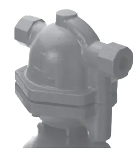
PRODUCT DESCRIPTION
The FXT300 Series are float and thermostatic steam traps. Float is free of levers, linkages or other mechanical connections. This float is weighted to maintain orientation and acts as the valve being free to modulate condensate through the seat ring. Air vent is balanced-pressure design with stainless steel welded encapsulated bellows capable of discharging air and non-condensable gases continuously within 15°F (-9.4°C) of saturated temperature.
SPECIFICATIONS
The specifications section on this page provide the ratings and other specifications for the FXT300 Series.
- Available
- Configurations: Type FXT300
- (Low capacity)
- Type FXT301
- (Medium capacity)
- Type FXT302
- (High capacity)
- Type FXT303
- (Super high capacity)
- Body Sizes and
- End Connections: NPT:
- ½” (12.7 mm),
- ¾” (19.1 mm), 1″ (25.4 mm),
- 1½” (38.1 mm) and
- 2″ (50.8 mm)
- CL250 RF Flanged:
- NPS 1½ (DN 40) and
- 2 (DN 50)
- Maximum Allowable
- Pressure(1): 250 psig (17.2 barg)
- Maximum
- Operating
- Pressure(1): See Table 1
- Maximum Allowable
- Temperature: 450°F (232°C)
- Materials of
- Construction: Body and Cover: Cast iron
- ASTM A126B
- Cover Gasket:
- Graphite fiber
- All Internal Parts:
- Stainless steel
- Air Vent:
- Stainless steel
- Options: SLR Orifice
- Blowdown Valve
- Orifice Continuous Bleed
- Air Vent
PRINCIPLE OF OPERATION
On startup, the thermostatic air vent, caged stainless welded bellows, is open, allowing air to flow freely through the vent valve orifice. When condensate flows into the trap, the float rises, allowing condensate to be discharged. Once air and non-condensables have been evacuated, hot condensate will cause the thermostatic vent to close. Condensate
will continue to be discharged as long as condensation occurs. During normal operation, an increase in the load causes the liquid level in the trap to rise. The float then rises and rolls off the seat ring, allowing more condensate to flow out. The float sinks as the condensate load decreases, moving nearer to the seat ring, decreasing the effective size of the orifice and allowing less condensate to discharge. This provides smooth, continuous operation that reacts instantly to load variation while maintaining a water seal over the seat ring to prevent live steam loss.
INSTALLATION
Install the FXT300 Series Steam Trap upright and in a horizontal line with the arrow on the body pointing in the direction of flow. Allowable inclination is 5° or less horizontally and 5° or less at right angles to the plane of the pipe line.
FIGURE 1: FXT300 and FXT301 Series Steam Trap Operational Schematic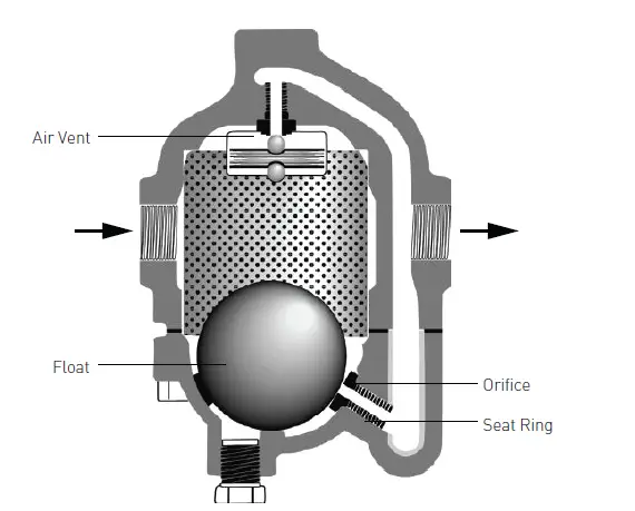
MAINTENANCE
Due to normal wear that may occur, inspect the parts periodically and replace if necessary. The frequency of inspection depends on the severity of service conditions.
TABLE 1. MAXIMUM OPERATING PRESSURE
| ORIFICE 20 | MAXIMUM OPERATING PRESSURE | |
| psig barg | ||
| 20 | 1.4 | |
| 50 | 50 | 3.5 |
| 100 | 100 | 6.9 |
| 150 | 150 | 10.3 |
| 175 | 175 | 12.1 |
| 250 | 250 | 17.2 |
TABLE 2. FXT250 SERIES STEAM TRAP TORQUE VALUES
| TRAP TYPE FXT300 | BODY BOLTS SEAT RING SEAT RING | |||||
| Ft-lb | N•m | Ft-lb | N•m | in-lb | N•m | |
| 25 to 30 | 33.9 to 40.7 | – – – – | – – – – | 78 to 84 | 8.81 to 9.49 | |
| FXT301 | 60 to 70 | 81.4 to 94.9 | – – – – | – – – – | 132 to 134 | 14.9 to 15.1 |
| FXT302 | 60 to 70 | 81.4 to 94.9 | 21.5 to 23.5 | 29.2 to 31.9 | – – – – | – – – – |
| FXT303 | 115 to 135 | 156 to 183 | 37 to 41 | 50.2 to 55.6 | – – – – | – – – – |
CAUTION
Inspection of the thermostatic bellows is not recommended as disassembly generally damages the unit.
- Disassemble the steam trap.
- Remove the body bolts and place the lower body on a safe place.
- Inspect the float and lower seat ring for damage and clean or replace as necessary. Clean the float with a rag and steel wool.
- Clean the screen using a wire brush.
- Replace bellows if needed. Use needle nose pliers or similar tool. Insert them into two of the three holes located in the bellows assembly and unscrew it from the upper body.
NOTE: When reassembling, use threadlocker on the bellows assembly threads. - After inspection or repair, reassemble trap by replacing body gasket and torquing bolts as specified, see Table 2.
FIGURE 2: FXT300 AND FXT301 SERIES STEAM TRAP ½ TO 2 NPT ASSEMBLY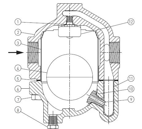
PARTS ORDERING
When corresponding with your local Sales Office about FXT300 Series Steam Trap, always reference the assembly number. When ordering replacement parts specify the complete character part number from the following parts list.
PARTS LIST
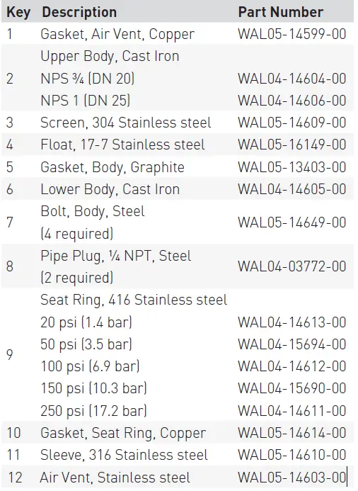
TABLE 3. FXT300 SERIES STEAM TRAP TORQUE VALUES
| NFT TRAP MODEL | REPAIR KIT(1)(2) | PCA SEAT KIT(3) | AIR VENT KIT(4)(5) | GASKET KIT(6) |
| FXT300-20 | WAL5590110 | WAL5590012 | ||
| FXT300-50 | WAL5590210 | WAL5590211 | ||
| FXT300-100 | WAL5590410 | WAL5590111 | WAL33379 | WAL5590411 |
| FXT300-150 | WAL5590510 | WAL5590511 | ||
| FXT300-250 | WAL5590710 | WAL5590711 | ||
| FXT301-20 FXT301-50 FXT301-100 FXT301-150 FXT301-250 | WAL5590130 WAL5590230 WAL5590430 WAL5590530 WAL5590730 |
WAL5590131 |
WAL33385 | WAL5590032 WAL5590231 WAL5590431 WAL5590531 WAL5590731 |
| FXT302-20 | WAL5590150 | WAL5590052 | ||
| FXT302-50 | WAL5590250 | WAL5590251 | ||
| FXT302-100 | WAL5590450 | WAL5590151 | WAL33390 | WAL5590451 |
| FXT302-150 | WAL5590550 | WAL5590551 | ||
| FXT302-250 | WAL5590750 | WAL5590751 | ||
| FXT303-20 FXT303-50 FXT303-100 FXT303-150 FXT303-250 | WAL5590170 WAL5590270 WAL5590470 WAL5590570 WAL5590770 |
WAL5590171 |
WAL33395 | WAL5590072 WAL5590271 WAL5590471 WAL5590571 WAL5590771 |
- Includes body gasket/s, air vent, air vent gasket, seat, seat gasket, screen, screen cap, float, tag and IOM.
- For repair kit option, add “-SLR” to the end of the part number for the Steam Lock Release option.
- Includes body gasket/s, seat, seat gasket, tag and IOM.
- Includes body gasket/s, air vent, air vent gasket, tag and IOM.
- Air vent tool part number is 04-15832-01.
- Includes one body gasket. Some kits may include two gaskets as a kit for one FXT trap.
- VCIOM-16916 © 2021, 2022 Emerson Electric Co. All rights reserved 06/22. Yarway is a mark owned by one of the companies in the Emerson Automation Solutions businessunit of Emerson Electric Co. The Emerson logo is a trademark and service mark of Emerson Electric Co. All other marks are the property of their prospective owners.
- The contents of this publication are presented for informational purposes only, and while every effort has been made to ensure their accuracy, they are not to be construed as warranties or guarantees, express or implied, regarding the products or services described herein or their use or applicability. All sales are governed by our terms and conditions, which are available upon request. We reserve the right to modify or improve the designs or specifications of such products at any time without notice.
- Emerson Electric Co. does not assume responsibility for the selection, use or maintenance of any product. Responsibility for proper selection, use and maintenance of any
- Emerson Electric Co. product remains solely with the purchaser.
Emerson.com


