![]()
Installation Instructions
SpaceLogic Sensors Air Quality Sensors Analog

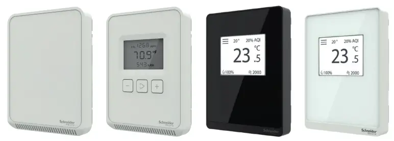
Note: A subset of models shown.
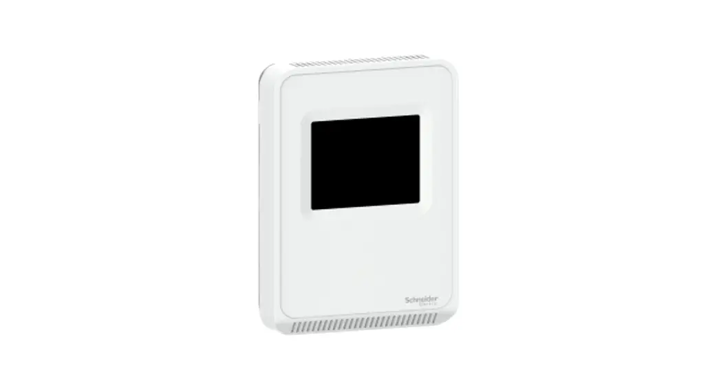
Product Description
The SpaceLogic SLA Series of air quality sensors for living space is a flexible multisensor platform for use with BAS controllers designed to accept 4 to 20mA, 0 to 5Vdc, or 0 to 10Vdc outputs. Housings are available in Medium matte white and Optimum faces are available in black and white. All housing types are available with three user interface options: touchscreen, LCD with three buttons, and blank. CO2 and temperature sensors are included with all SLA Series air quality sensors. Models with VOC sensors and relative humidity sensors are also available.
Features
- Medium matte white housing or optimum glass panel housing available in white or black
- Field calibratable non-dispersive infrared CO2 sensor
- Replaceable RH element available in 1% & 2% with NIST certificate
- VOC sensor available
- Temperature output on all models
- 61 mm (2.4″) backlit color touchscreen and LCD, three-button display options available
– Digital temperature indication (0.1° display resolution of °F or °C
– Digital humidity indication (0.1% RH display resolution)
– Digital CO2 indication (1 ppm display resolution)
– Selectable temp, RH, and fan speed setpoint (0-10V)
– Configurable screen/button lock and display timeout
– Override - Selectable 4 to 20mA, 0 to 5V and 0 to 10V analog outputs
- 18-24 AWG screw terminals
Available Products Matrix
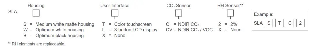
SpaceLogic Sensors, Air Quality Sensors – Analog Installation Instructions
Specifications
| Operating Environment | |||
| Input power | Class 2; 20 to 30 Vdc, 24 Vac, 50 to 60 Hz | ||
| Analog output | Selectable 4 to 20 mA, 0 to 5 V, 0 to 10 V | ||
| Operating temp. range | 0 to 50 °C (32 to 122 °F) | ||
| Operating humidity range | 0 to 95% RH non-condensing | ||
| Housing material | High impact ABS plastic | ||
| IP rating | IP 30 | ||
| CO2 Sensor | |||
| Sensor type | Non-dispersive infrared (NDIR), diffusion sampling | ||
| Output range | 0 to 2000/5000 ppm (selectable) | ||
| Accuracy | ±30 ppm ±3% of the measured value | ||
| Repeatability | ±20 ppm ±1% of the measured value | ||
| Response time | <60 seconds for 90% step change | ||
| VOC Sensor | |||
| Sensor type | Solid-state | ||
| Output range | 0 to 100% AQI for VOC | ||
| Accuracy | ±15% of the measured value | ||
| Output scale | 0 to 1,000 ppb of total VOC (TVOC) | ||
| AQI table* | Level | Ventilation Recommendation | TVOC (ppb) |
| >61% | Greatly increased | >610 | |
| 20 to 61% | Significantly increased | 200 to 610 | |
| 10 to 20% | Average | 100 to 200 | |
| 5 to 10% | Target value | 50 to 100 | |
| 0 to 5% | Greatly increased | 0 to 50 | |
| RH Sensor | |||
| HS sensor | Thin-film capacitive, replaceable | ||
| Accuracy | ±2% from 10 to 80% RH @ 25°C (77 °F) | ||
| Hysteresis | 1.5% typical | ||
| Linearity | Included in accuracy specification | ||
| Stability | ±1% @ 20°C (68 °F) annually for 2 years | ||
| Output range | 0 to 100% RH | ||
| Temperature coefficient | ±0.1% RH/°C above or below 25 °C (77 °F) typical | ||
| Temperature Sensor | |||
| Sensor type | Solid-state, integrated circuit | ||
| Accuracy | ±0.2 °C (±0.4 °F) typical | ||
| Resolution | 0.1 °C (0.1 °F) | ||
| Range | 0 to 50 °C (32 to 122 °F) | ||
| Display Models | |
| Touchscreen | 61 mm (2.4 in), color, backlit, capacitive, 240x300px Setpoint: 0-10Vdc. Temperature, humidity, or fan speed selectable |
| LCD | 52mm (2.05 in), segmented with 3 buttons Setpoint: 0-10Vdc. Temperature, humidity, or fan speed selectable Timeout override: Display timeout** Lockout override: Touchscreen/button lockout** |
| Setpoints*** | |
| Temperature setpoint | 0 to 10V output Scale: 10 to 35 °C (50 to 95 °F) /0 to 50 °C (32 to 122 °F) |
| Humidity setpoint | 0 to 10V output Scale: 0 to 100% RH |
| Fan speed setpoint | 0 to 10V output Off 0V, Low 3.3V, Med. 6.7V, High 10.0V |
| Override | |
| Override button | Display models feature a momentary-to-ground override button |
| Wiring Terminals | |
| Terminal blocks | Screw terminals, 18-24 AWG |
| Screw terminal torque | 0.2 N-m (2.0 in-lbF) max. |
| Regulatory Information | |
| Agency approvals | UL 916, European conformance CE: EN61000-6-2 EN61000-6- EN61000 Series – industrial immunity EN 61326-1 FCC Part 15 Class B, REACH, RoHS, Green Premium, RCM (Australia), ICES-003 (Canada),EAC (Russia) |
* Air Quality Index for VOC aligns with TVOC levels for IAQ as specified by the WHO (World Health Organization).
** DIP switch selectable.
*** One setpoint type is selectable via a DIP switch on display models only.
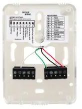
Installation
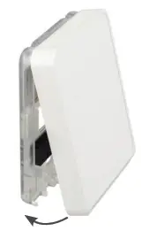
- Remove the cover from the base at the bottom of the device.

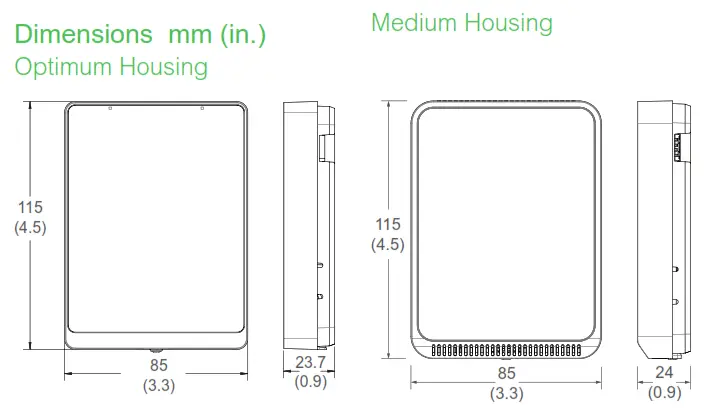
- Position the sensor base vertically on the wall 1.35 m (4.5ft.) above the floor with the “UP” arrow facing upward. Locate away from windows, vents, and other sources of the draft. If possible, do not mount on an external wall, as this may cause inaccurate temperature readings.

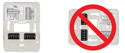
- Pull 18 or 22 AWG cable(s) through the hole in the backplate.

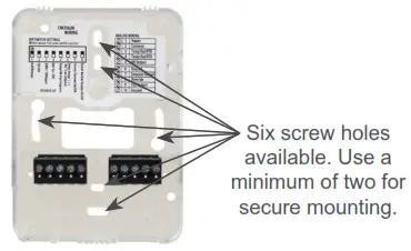
- Mount the backplate onto the wall using the screws provided.

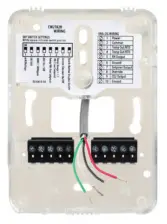
- Connect the wires to the screw terminals. Do not over-tighten the screws.

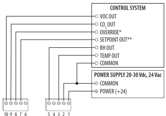
Wiring diagram:
- Set the DIP switches.
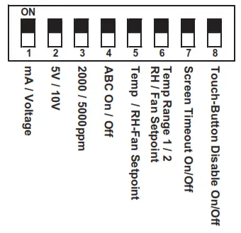
| Switch | Function | Description |
| 1 | Output mode | ON – 4-20mA output mode enabled OFF – Voltage output mode enabled |
| 2 | Voltage output range* | ON – 0-5V output range enabled OFF 0-10V output range enabled |
| 3 | CO2 output range | ON – 0-2000 ppm CO2 output range enabled OFF – 0-5000 ppm CO2 output range enabled |
| 4 | Automatic Baseline Calibration (ABC) for CO2 | ON – ABC enabled OFF – ABC disabled |
| 5 | Setpoint output type | ON – Temperature setpoint enabled (temp range selected on DIP switch 6) OFF – RH or Fan Speed setpoint enabled (specific setpoint output type to be selected on DIP witch6) Models without RH option select only temp or fan setpoint |
| 6 7 | Setpoint output temperature range or RH/Fan Speed output type | Temperature setpoint (must be enabled on DIP switch 5) ON – Temp range 1, 50 to 95 °F (10 to 35 °C) enabled OFF – Temp range 2, 32 to 122 °F (0 to 50 °C) enabled |
| RH or Fan Speed setpoint (must be enabled on DIP switch 5) ON – RH setpoint enabled OFF – Fan Speed setpoint enabled Models without RH option, set to OFF | ||
| 7 | Display times out and turns off after 6-10 seconds of touchscreen/ button press | ON – Display Timeout enabled OFF – Display Timeout disabled |
| 8 | Touchscreen touch functions and buttons are disabled | ON – Touchscreen touch/button functions disabled OFF – Touchscreen touch/button functions enabled |
* Only used with voltage output mode enabled. Not applicable to setpoint output. Setpoint is 0-10V fixed.
7. With the sensor base fully installed, align the top of the cover to mounting tabs on top of the sensor base. Swing cover downward until it latches at the bottom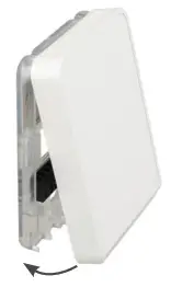 8. Install locking screw to secure cover in the closed position.
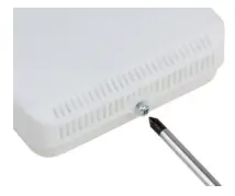
9. 400 ppm baseline calibration allows the sensor to be set at 400 ppm. Push and hold the calibration button for 3 to 5 seconds. The LED will flash green. Once the button is released, calibration is complete and the LED switches off. 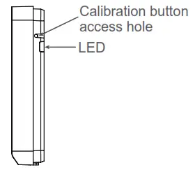
Touchscreen Operation
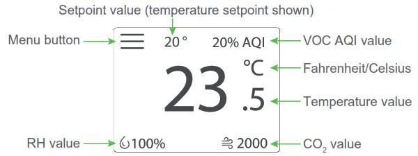
Main Screen
The touchscreen user interface displays applicable sensor output values (temperature, RH, CO2, and VOC), setpoint value, menu button, and CO2 stoplight status (if enabled).
Menu Screen
The menu screen opens when pressing the Menu button on the main screen. Integrator’s submenu, occupancy/override, Fahrenheit/Celsius, settings, setpoint submenu (temp, RH or fan, determined by DIP switch settings), and CO2 stoplight buttons are displayed on the menu screen.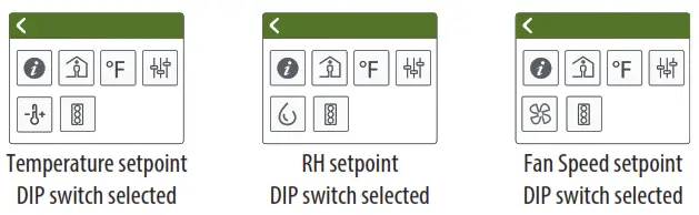
Menu Button Functions
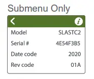
![]() Integrator’s Submenu Press this icon to access the Integrator’s menu.
Integrator’s Submenu Press this icon to access the Integrator’s menu.
![]() Occupied Override Button
Occupied Override Button
Press this icon to provide momentary ground output to the controller
![]() Single Press Only
Single Press Only
Signals occupied/override call to controller.
![]() Fahrenheit/Celsius Switch
Fahrenheit/Celsius Switch
Press this icon to display either °C or °F.
Single Press Only![]() Changes units to Fahrenheit when pressed.
Changes units to Fahrenheit when pressed.![]() Changes units to Celsius when pressed.
Changes units to Celsius when pressed.
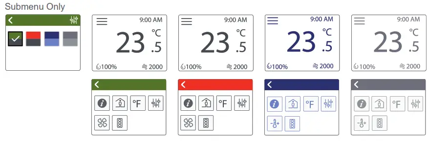
![]() Settings
Settings
This icon provides the ability to change the color scheme of the display.
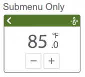
 Temp Setpoint Adjustment
Click this icon to access the setpoint change menu. Mutually exclusive with fan speed, set by DIP switch.
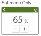
![]() Humidity Setpoint Adjustment
Humidity Setpoint Adjustment
Click this icon to access the setpoint change menu. Mutually exclusive with humidity and fan speed. Set by DIP switch.
Menu Button Functions (cont.)
![]() Fan Speed
Fan Speed
Click this icon to access the fan speed menu. Mutually exclusive with humidity and fan speed. Set by DIP switch.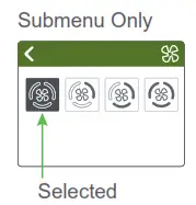
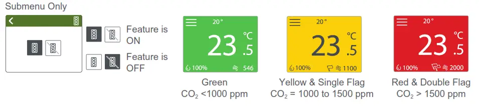
 CO2 Stoplight Menu
Click this icon to toggle the CO2 Stoplight feature on and off. With CO2 Stoplight turned on, the background color of the main screen changes with the CO2 level. This provides a visual indicator of CO2 levels to the room occupants.
LCD Display Operation
Button Functions
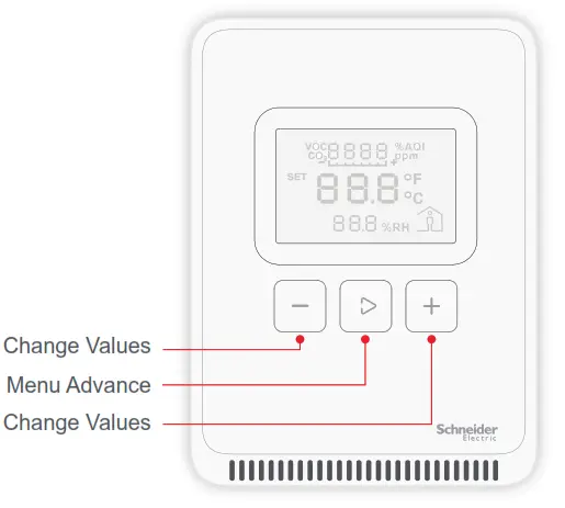
Display Icons
The main screen displays sensor values for CO2, VOC (if equipped), RH (if equipped), temperature, and Celsius/Fahrenheit.
![]()
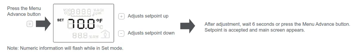
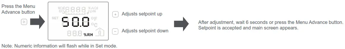
Setpoint Function
A single 0-10V set point (temperature, RH (if equipped), or fan speed) can be selected via a DIP switch.
Temperature Setpoint Adjustment
RH Setpoint Adjustment
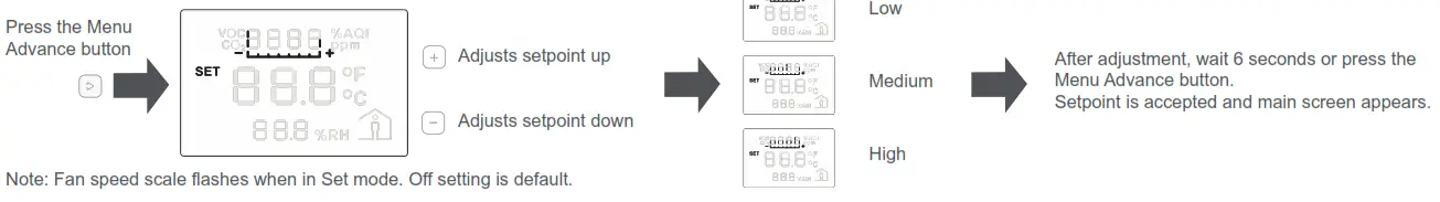
Fan Speed Setpoint Adjustment
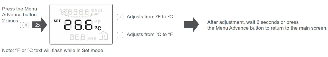
Changing Celsius and Fahrenheit scales
Occupied/Override Button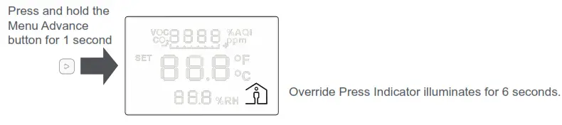
China RoHS Compliance Information
Environment-Friendly Use Period (EFUP) Table
| Hazardous Substances | ||||||
| Part Name | (Pb) | (Hg) | (Cd) | (Cr (VI)) | (PBB) | (PBDE) |
| Electronic | X | 0 | 0 | 0 | 0 | 0 |
This table is made according to SJ/T 11364.
O: indicates that the concentration of a hazardous substance in all of the homogeneous materials for this part is below the limit as stipulated in GB/T 26572.
X: indicates that concentration of a hazardous substance in at least one of the homogeneous materials used for this part is above the limit as stipulated in GB/T 26572
Z000057-0B![]()
USA: +1 888-444-1311
Europe: +46 10 478 2000
Asia: +65 6484 7877
www.schneider-electric.com
© 2021 Schneider Electric. All rights reserved. All trademarks are owned by Schneider Electric Industries SAS or its affiliated companies.


