![]()
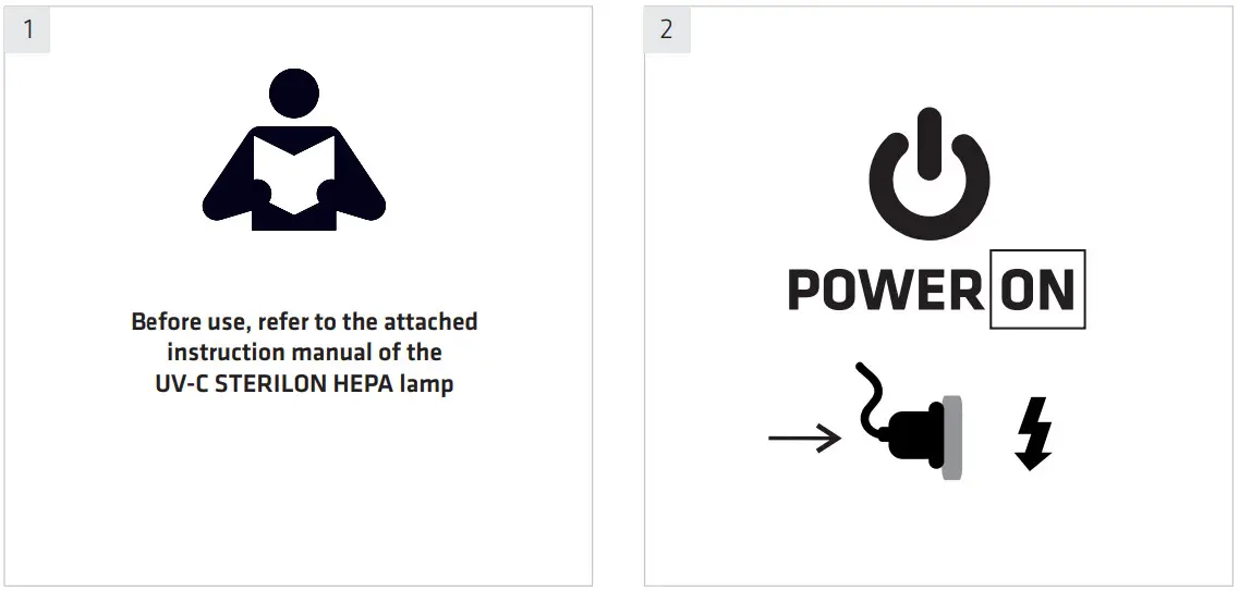
UV-C Sterilon Hepa LCD Control Panel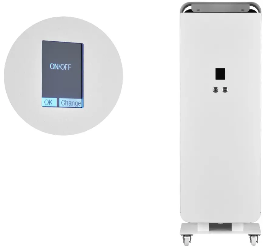 User Manual
UV-C Sterilon Hepa LCD Control Panel
GENERAL INFO
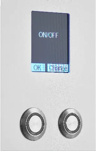
The left button is responsible for executing commands on the bar on the left-hand side of the screen, e.g. „ok”
The right button is responsible for executing commands on the bar on the right-hand side of the screen, e.g. „change”
ON/OFF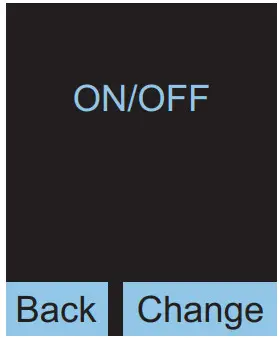
Basic mode – starts the UVC sterilisation with the possibility of adjusting the fan power in steps of 25-100%
FAN WITHOUT UVC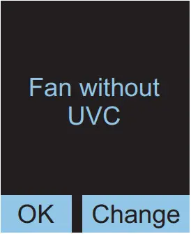
Starts the fan without UVC lamps, allowing air purification through the HEPA filter itself Fan power adjustment in steps of 25-100%
DELAY ON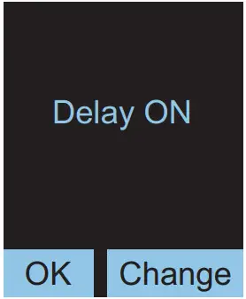
Possibility to start sterilisation with a specified power setting after a preset time
DELAY OFF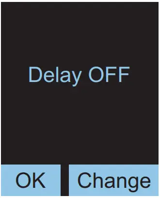
SYSTEM INFO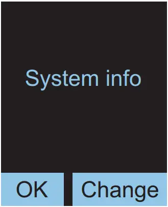
Possibility to check the lifetime of fluorescent lamps – 9000h by default
MENU – ON/OFF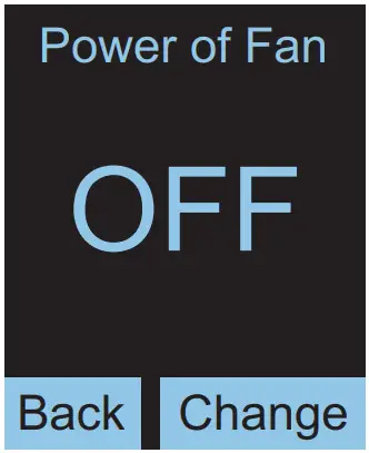
– „OFF” is set by default
– the change is made by pressing the „change” button
– all UVC lamps turn on when the fan is running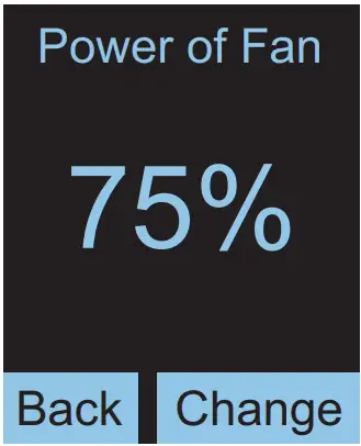
– the available fan speed settings are as follows: OFF, 25%, 50%, 75% and 100%
– the last selected power setting is remembered and is the default value upon subsequent activations of this mode Power of Fan
MENU – FAN WITHOUT UVC
The same as in the ON/OFF menu, except that the UVC lamps are not turned on
MENU – DELAY ON / Power of Fan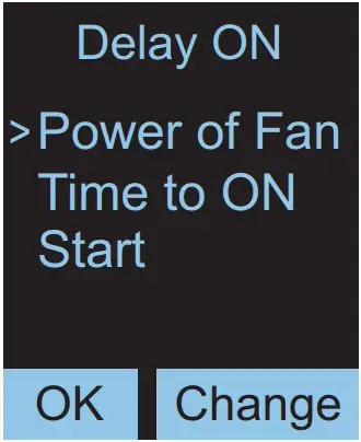
– setting the power with which the fan is to turn on during sterilisation after a preset time
– set as in the „on/off” menu
MENU – DELAY ON / Time to ON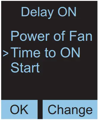
– setting the delay time for switching on
MENU – DELAY ON / Time to ON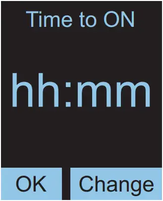
– after entering the „Time to on” submenu, set the delay time expressed in hours and minutes
– the maximum available values are 24h and 55 min
– the smallest time unit is 5 minutes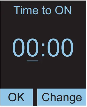
– pressing „ok” highlights the changed value
– to change the value, press the „change” button
– once 24h is reached, the value goes back to the start – i.e. 0h
– pressing „ok” again will take you to setting the minutes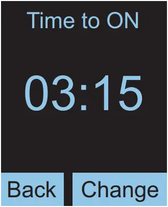
– another pressing „ok” will save the set time
– pressing the „back” button will take you back to the previous menu
MENU – DELAY ON / Start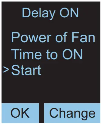
– selecting „Start” and pressing „ok” will start the countdown to disinfection 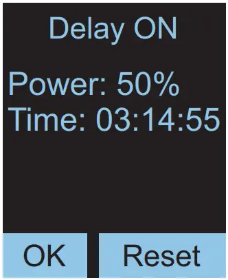
– the time remaining to activation is constantly refreshed
– the time can be reset by pressing the „reset” button
MENU – Delay OFF
– the same as in the Delay ON menu, except that the time to turn off the lamp is counted down, and the set fan power is the one with which the lamp is started once the „Start” option is selected
MENU – SYSTEM INFO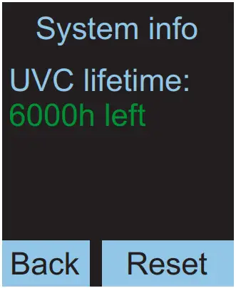
– the operation time meter shows the approximate lifetime of fluorescent lamps – how much time is left to the recommended replacement
– the default set lifetime of fluorescent lamps is 9000 hours
ALARM MESSAGES 
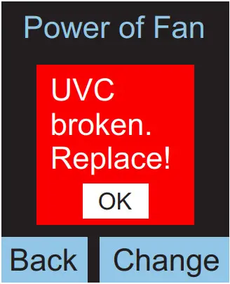
– The following alarm messages may be displayed on the display during operation of the device.
– If any of the UVC lamps is damaged, the “UVC broken. Replace!” message is displayed. In this case, disconnect the device from the power supply and replace the appropriate fluorescent lamp. If not replaced, only the “Fan without UVC” operating mode will be functional.
– The message disappears after any button is pressed or the device is restarted.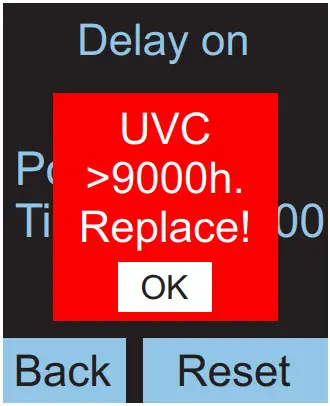
– In the case of continuous lighting of fluorescent lamps for more than 9000h, the message “UVC> 9000h. Replace!” is displayed.
– The message disappears after any button is pressed or the device is restarted.
– The message does not interfere with the normal operation of the device, but it will be displayed again after the next hour.
– To eliminate it, reset the runtime counter in the “System info” menu.
 We would like to inform you that our product’s are marked in accordance with the European Directive 2002/96/CE and Polish Act o n used electric and electronic equipment with a sign of a crossed-out waste container:
This mark informs abort the fact that the device, after its application use, cannot be placed together with other types of household waste. The user is obliged to return it to the entities conducting a collection of used electric and electronic equipment. The collection points, including local collection points, shops and municipal entities create a proper system making it possible for the return of the equipment. Proper proceeding with used electric and electronic equipment contributes to the avoidance of damaging consequences for the health of the inhabitants and natural environment chick result form the presence of dangerous substances and improper storage and processing of such devices and equipment.
![]() tel. +48 61 28 60 300
tel. +48 61 28 60 300
e-mail: [email protected]
www.lenalighting.pl
LENA LIGHTING S.A.
ul.Kornicka 52, 63-000 Sroda Wlkp.
POLAND
Data aktualizacji/Date of update: 6.12.2021


