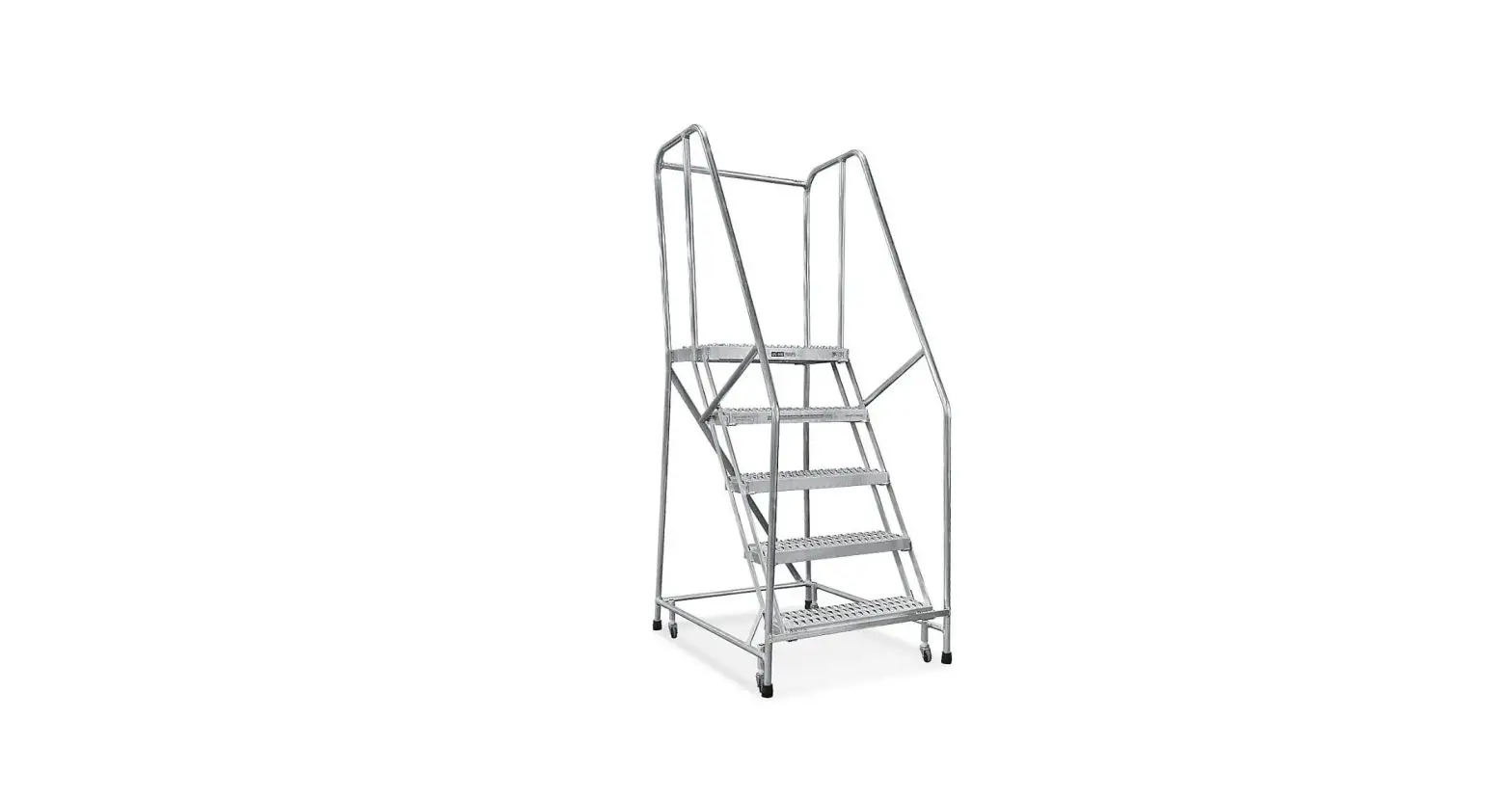
ULINE 3-4 Step Rolling Safety Ladders 10″ Deep Top Step Installation Guide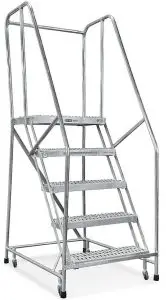
TOOLS NEEDED
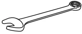
- 9/16″ (14 mm) Wrench (2)

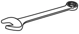
- 7/16″ (11 mm) Wrench or Socket

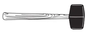
- Rubber Mallet

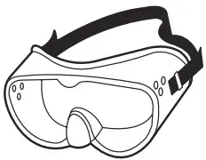
- Safety Glasses

PARTS
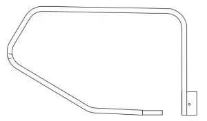
- A. Side Handrail (1)

- B. Side Handrail (1) Opposite
Handrail Brackets (2) (shipped attached to handrail)

- C. Rear Handrail Bar (1) (shipped taped to top of handrail)

- F. Back Panel (1)

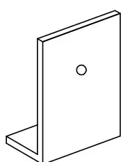
- D. Stile (1)

- E. Bottom Bars (2)

- Gray Bushings (2)

- Notched Bushings (2)

- Hardware Kit (1) (misc. hardware included)

ASSEMBLY
WARNING! Assembly of these types of ladder scan be inherently dangerous. Please take all precautions necessary during the assembly process. Always use a separate ladder to finish assembly in high places. Never climb a ladder that is not completely assembled. Do not assemble or use a ladder with missing or damaged parts. Use proper lifting mechanics when assembling a ladder. Watch for overhead electrical hazards and obstructions.
STEP 1: BACK PANEL ASSEMBLY
NOTE: DO NOT tighten bolts until instructed to.
- Place the ladder stile (D) on the floor. Be sure to assemble on a protective surface so the finish does not get damaged.
- Bolt back panel (F) to the insides of lugs 1 with (2) 3/8-16 x 1¼” hex head cap screws and self-locking nuts. (See Figure 1)

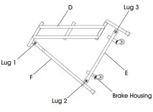
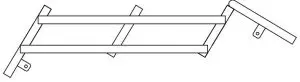
STEP 2: ASSEMBLY OF BOTTOM BARS
- Bolt bottom bar (E) to the insides of lugs 3 with (2) 3/8-16 x 1¼” hex head cap screw, and self-locking nuts. (See Figure 1)
- Bolt other end of bottom bar (E) to the inside of lug 2 on back panel. (See Figure 1)
- Repeat on opposite side with other bottom bar.
- If rubber tips have not been installed prior to shipping, slip rubber tips onto the ends of the legs.
NOTE: Brake housing must be on the inside of the bottom bars (E) with the large opening facing away from the stile. (See Figure 1)
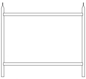
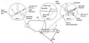
STEP 3: INSTALL HANDRAILS
CAUTION: NEVER climb a ladder that is not completely assembled.
- Install side handrail (A) into the rear stile tubes. Use the rubber mallet as needed for mating parts. (See Figure 2, Step 1)
- Detach handrail brackets that are shipped attached to handrail.
- Clamp side handrail to outside of stile tubes using detached handrail brackets and 3/8-16 x 2″ hex head cap screws (H.H.C.S.), gray bushings and selflocking nuts. (See Figure 2, Step 2)

STEP 4: LEVEL LADDER
- Stand ladder upright on level surface.
- Weight ladder to compress casters making sure ladder rests level on all four legs.
- When steps are level, tighten all installed bolts.
- Repeat step 1 through 3 with handrail (B).
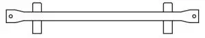
- Detach rear handrail bar (C) from handrail.
- Insert notched bushing into each end of rear handrail bar (C).
- Position rear handrail bar between mounting holes of side handrails (A) and (B). Attach using (2) 1/4-20 x 1¼” hex head cap screws. (See Figure 2, Step 3)
NOTE: You may now tighten all handrail bolts.
Contact: 1-800-295-5510
Website: uline.com


