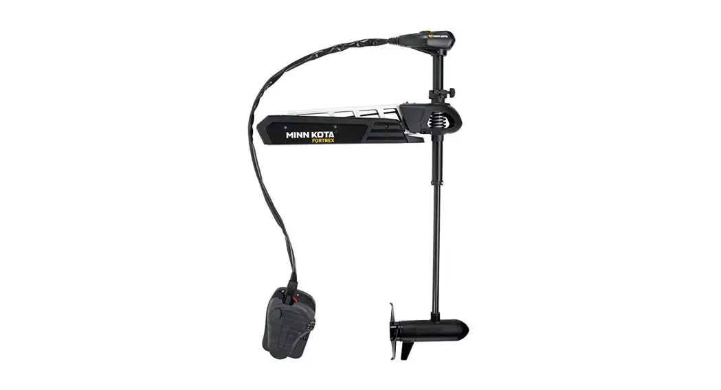
![]() FORTREX®
FORTREX®
BOW-MOUNT TROLLING MOTOR
Installation Instructions
INTRODUCTION
THANK YOU
Thank you for choosing Minn Kota. We believe that you should spend more time fishing and less time positioning your boat. That’s why we build the smartest, toughest, most intuitive trolling motors on the water. Every aspect of a Minn Kota trolling motor is thought out and rethought until it’s good enough to bear our name. Countless hours of research and testing provide you the Minn Kota advantage that can truly take you “Anywhere. Anytime.” We don’t believe in shortcuts. We are Minn Kota. And we are never done helping you catch more fish.
REGISTRATION
Remember to keep your receipt and immediately register your trolling motor. A registration card is included with your motor or you can complete registration on our website at
minnkotamotors.com.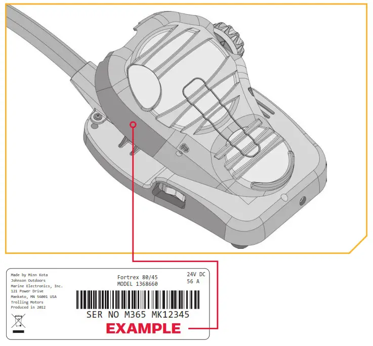 SERIAL NUMBER
Your Minn Kota 11-character serial number is very important. It helps to determine the specific model and year of manufacture. When contacting Consumer Service or registering your product, you will need to know your product’s serial number. We recommend that you write the serial number down so that you have it available for future reference.
NOTICE: The serial number on your Fortrex is located near the Momentary Switch underneath the side of the Foot Pedal.
MOTOR INFORMATION (For Consumer Reference Only)
Model: ______________________________________
Serial Number: __________________________________
Purchase Date: _________________________________
Store Where Purchased: ________________________
NOTICE: Do not return your Minn Kota motor to your retailer. Your retailer is not authorized to repair or replace this unit. You may obtain service by calling Minn Kota at 800) 227-6433; returning your motor to the Minn Kota Factory Service Center; sending or taking your motor to any Minn Kota authorized service center. A list of authorized service centers is available on our website, at minnkotamotors.com. Please include proof of purchase, serial number, and purchase date for warranty service with any of the above options.
SAFETY CONSIDERATIONS
Please thoroughly read the user manual. Follow all instructions and heed all safety and cautionary notices. Use of this motor is only permitted for persons that have read and understood these user instructions. Minors may use this motor only under adult supervision. WARNING
You are responsible for the safe and prudent operation of your vessel. We have designed your Minn Kota product to be an accurate and reliable tool that will enhance boat operation and improve your ability to catch fish. This product does not relieve you from the responsibility for the safe operation of your boat. You must avoid hazards to navigation and always maintain a permanent watch so you can respond to situations as they develop. You must always be prepared to regain manual control of your boat. Learn to operate your Minn Kota product in an area free from hazards and obstacles.WARNING
Never run the motor out of the water, as this may result in injuries from the rotating propeller. The motor should be disconnected from the power source when it is not in use or is off the water. When connecting the power-supply cables of the motor to the battery, ensure that they are not kinked or subject to chafe and route them in such a way that persons cannot trip over them. Before using the motor make sure that the insulation of the power cables is not damaged. Disregarding these safety precautions may result in electric shorts of battery(s) and/or motor. Always disconnect the motor from the battery(s) before cleaning or checking the propeller. Avoid submerging the complete motor as water may enter the lower unit through the control head and shaft. If the motor is used while water is present in the lower unit considerable damage to the motor can occur. This damage will not be covered by warranty.WARNING
Take care that neither you nor other persons approach the turning propeller too closely, neither with body parts nor with objects. The motor is powerful and may endanger or injure you or others. While the motor is running watch out for a person swimming and for floating objects. Persons who lack the ability to run the motor or whose reactions are impaired by alcohol, drugs, medication, or other substances are not permitted to use this motor. This motor is not suitable for use in strong currents. The constant noise pressure level of the motor during use is less than 70dB(A). The overall vibration level does not exceed 2,5 m/sec2.WARNING
When stowing or deploying the motor, keep fingers clear of all hinge and pivot points and all moving parts. In the event of an unexpected operation, remove power leads from the battery.WARNING
It is recommended to only use Johnson Outdoors approved accessories with your Minn Kota motor. Using non-approved accessories including to mount or control your motor may cause damage, unexpected motor operation, and injury. Be sure to use the product and approved accessories, including remotes, safely and in the manner directed to avoid accidental or unexpected motor operation. Keep all factory-installed parts in place including motor and accessory covers, enclosures, and guards.
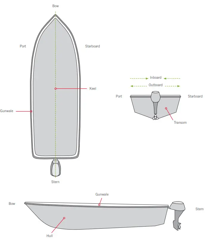
KNOW YOUR BOAT
INSTALLATION
INSTALLING THE FOR TREX
Your new Fortrex comes with everything you’ll need to directly install it to the boat. This motor can be directly mounted to the boat or coupled with a Minn Kota quick release bracket for ease of mounting and removal. For installation with a quick-release bracket, refer to the installation instructions provided with the bracket. For compatible quick-release mounting brackets, please visit minnkotamotors.com. To install the motor directly to the boat, please follow the instructions provided in this manual. Please review the parts list, mounting considerations, and tools needed for installation prior to getting started. For additional product support and to locate your nearest dealer, please visit minnkotamotors.com.
INSTALLATION PARTS LIST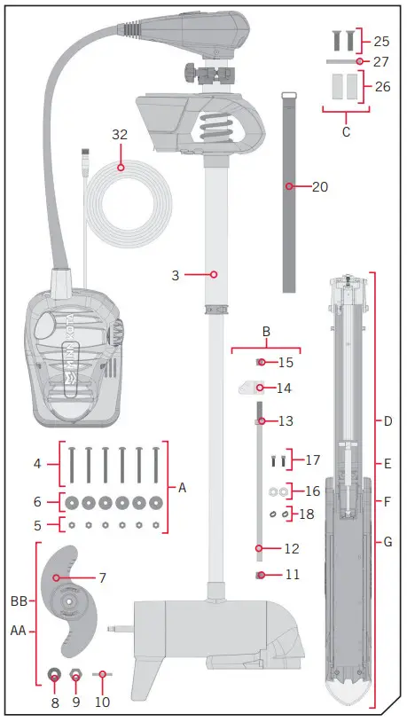
| Item i Assembly | Part # | Description | Qty. |
| 3 | X | MOTOR ASSEMBLY | 1 |
| A | 2994887 | INSTALLATION HARDWARE BAG ASSEMBLY | 1 |
| 4 | 2263468 | 1/4 – 20 X 2.5″ SS PPH SCREW | 6 |
| 5 | 2263103 | 1/4 – 20 SS NYLOCK NUT | 6 |
| 6 | 2261713 | 1/4 FLAT 18-8 SS WASHER | 6 |
| AA | 1378132 | 80# THRUST PROP KIT | 1 |
| BB | 1378160 | I12# THRUST PROP KIT | 1 |
| 7 | 7341160 | PROP-MY? (4 5)W/ADPRING | 1 |
| 8 | 2091701 | WASHER-PROP (LARGE) | 1 |
| 9 | 2093101 | NUT-PROP NYLOC, LG, MX101 3/8 SS | 1 |
| 10 | 2262658 | PIN-DRIVE 1″ 3/16° S/S | 1 |
| B | 29919250 | BRACKET STABLZR ARM ASY (SUB) | 1 |
| 11 | 22655100 | BUMPER STABILIZER | 1 |
| 12 | 2263624 | STABILIZER ROD | 1 |
| 13 | 2263107 | NYLON HEX NUT 3/4 – 10 UNC | 1 |
| 14 | 2281829 | BRACKET | 1 |
| 15 | 2260221 | VINYL CAP | 1 |
| 16 | 2223100 | NUT 5/16-18 NYLONS SS | 2 |
| 17 | 2263422 | BOLT 5/16-18 X 1″ SS CAP SCREW | 2 |
| 18 | 2281700 | 5/16 “ID X .457 OD HIGH COLLAR LOCK WASHER | 2 |
| 20 | 2773806 | STRAP. HOLD DOWN | 1 |
| C | 2994912 | BAG ASSY, FORTREX MOUNT HDW | 1 |
| 25 | 2283410 | SCREW-1/4-20 X .500′ PFH | 2 |
| 26 | 2281710 | SPACER, GAS SPRING, FOR TREX | 2 |
| 27 | 2282610 | PIN. UPPER SHOCK | 1 |
| 2287110 | INSTALLATION GUIDE, FORTREX | 1 | |
| D | 2991650 | MNT /V/ 80# 45″. 112#/1-IC 52 A80 LB45’* “112 LB 52″” | 1 |
| E | 2991652 | MNTASM FIX FW 80# 52/62″ *80 LB 52’* *80 LB 62″* | 1 |
| F | 2991653 | MNT ASM FTX BY I12# 45″ A112 LB 45″A | 1 |
| G | 2991654 | MNT ASM FIX PM 112# 52″ *112 LB 52″* | 1 |
| 32 | 2211415 + | CABLE-EXTENSION, PD/AP 110″ *PRE-INSTALLED” | 1 |
![]() Not shown on Parts Diagram.
Not shown on Parts Diagram.
✖ This part is included in an assembly and cannot be ordered individually.
+Only available with models factory installed with Universal Sonar.![]() The Bow-Mount Stabilizer Assembly is not required or included on the 80lb 45” Fortrex.
The Bow-Mount Stabilizer Assembly is not required or included on the 80lb 45” Fortrex.
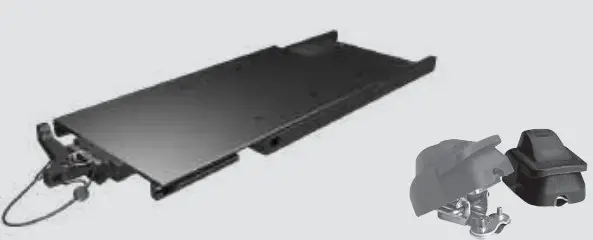
ASSEMBLY OF BOWGUARd TO MOUNT
MOUNTING CONSIdERATIONS
It is recommended that the motor be mounted as close to the keel or centerline of the boat as possible. Make sure the area under the mounting location is clear to drill holes and install nuts and washers. Make sure the motor rest is positioned far enough beyond the edge of the boat. The motor must not encounter any obstructions as it is lowered into the water or raised into the boat when stowed and deployed. Consider a quick release or adapter bracket with the installation of your motor. To view a list of accessories, please visit minnkotamotors.com.
 View accessories available for your trolling motor at minnkotamotors.com.
TOOLS ANd RESOURCES REQUIRED
| • #2 Phillips Screwdriver • (2) #3 Phillips Screwdriver • 1/4″ Allen Wrench • Drill | • 9/32″ Drill Bit • 7/16″ Box End Wrench • A person to help with installation |
| • Torque Wrench • File or Sandpaper • Hack Saw • Marker or Pencil | • 1/8″ Flat Screwdriver • 1/8″ Allen Wrench • Loctite |
INSTALLATION
Assembly of BowGuard to Mount
a. Place the Mount on an elevated, level surface such as a workbench or the tailgate of a pickup. The Mount, as removed from the box, should be in the deployed position.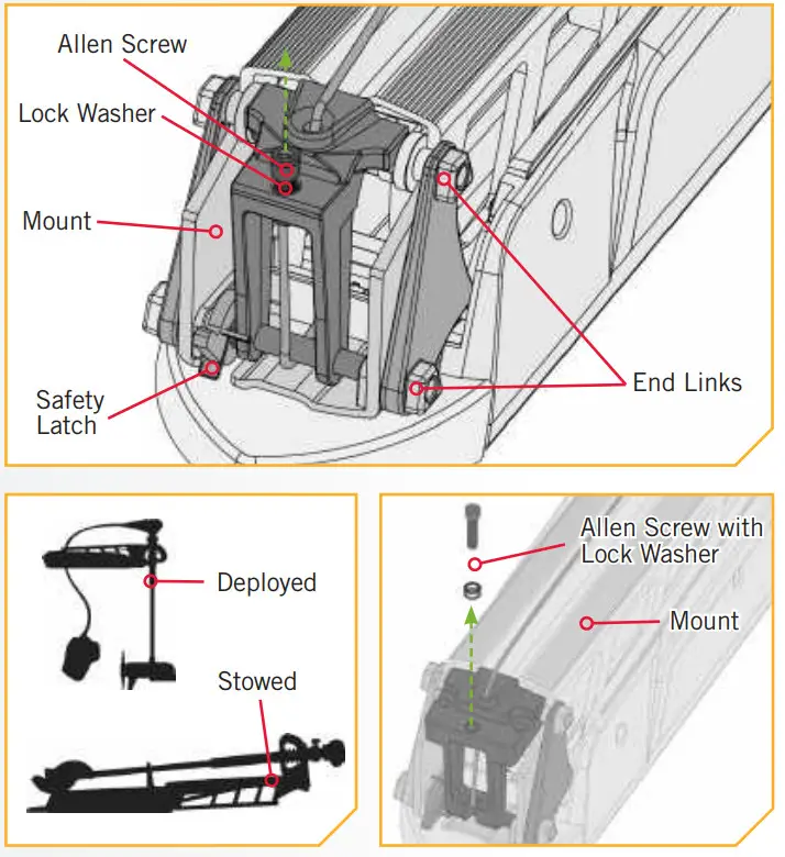 b. Remove the 5/16″ Allen Screw and Lock Washer from the Mount using the 1/4″ Allen Wrench. The 5/16″ Allen Screw is located on the opposite end of the mount from the hinge that opens and closes when the mount is stowed and deployed.
NOTICE: This motor weighs approximately 55 lbs. We recommend having a second person help with the installation.
c. Align the Keyways on the inside of the BowGuard with the End Links on the Mount. Lower the motor assembly straight down until seated.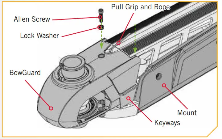 d. Install the 5/16” Allen Screw and the Lock Washer and tighten to 10-12 ft/lbs.WARNING
Carefully lower the Bowguard into place to avoid creating a pinch point between the Bowguard and Mount.
NOTICE: The 5/16” Allen Screw must be tight when installed and periodically tightened to 1012 ft/lbs. This will allow the motor to be stowed properly. Tighten the Allen Screw when the Mount is in the deployed position.
Installing the Mount
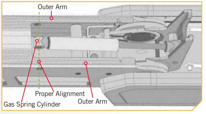
During installation, it is recommended to mount the motor to the boat before installing the Gas Spring Pin. The Gas Spring Pin is installed in the Gas Spring Cylinder. The Gas Spring Cylinder is located on the inside of the Outer Arm, which is a part of the Mount. At this point in the installation, the Gas Spring Cylinder is not fully installed and may move around inside the Mount when stowing and deploying the motor. The Gas Spring Cylinder can become damaged while deploying the motor and the damage will prevent the Lift-Assist feature from operating correctly once fully assembled. Make sure that the Gas Spring Cylinder does not get damaged in the Mount.
ITEM(S) NEEDED
![]()
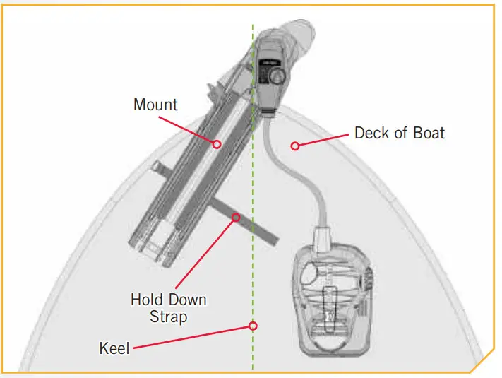
a. Review the mounting considerations at the beginning of the Installation section for proper placement. Place the Mount as close to the centerline or keel of the boat as ossible, with the motor in the stowed position, on the deck of the boat. Check placement with the motor in the stowed and deployed positions.CAUTION
The Gas Spring Cylinder can become damaged in the Mount while stowing or deploying the motor because it is not yet fully installed. Damage will prevent the Lift-Assist feature from operating correctly once fully assembled. Make sure that the Gas Spring Cylinder does not get damaged by keeping it inside the Outer Arm of the Mount.
b. Stow the motor into the flat position by pulling the Pull Grip and Rope to disengage the latch bar, allowing the motor to fold into the flat position.
c. Place the Hold-Down Strap (Item #20) under the base of the Mount Plate so that it is below the Mount when placed.
d. The Mount can be installed on either the Port or Starboard side of the boat based on personal preference. Test the placement of the Hold-Down Strap to be sure it can hold the Mount as placed. The placement of the buckle on the Hold-Down Strap either inboard or outboard is based on personal preference. The hook and loop on the fastener should e face down for the Hold-Down Strap to function.
e. Check the placement with the motor in the deployed position. When the motor is in the deployed position, make sure that the Shaft is 1-1/2″ out past the Gunwale of the boat. The lower unit, when stowed and deployed must not encounter any obstructions.
f. Check the placement of the Hold-Down Strap when the motor is in the stowed and deployed position and adjust if necessary.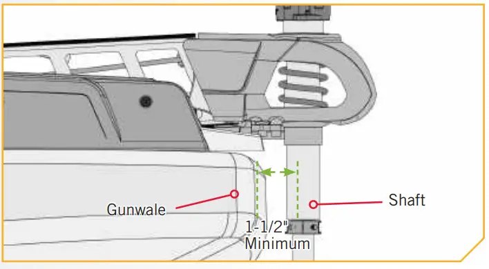 g. Once the Mount is in position, determine which bolt pattern to use. The bolt pattern selected will depend on the deck space available on your boat.
NOTICE: If Pattern 2 is used, the right side plate must be removed to access the mounting holes in the base of the Mount.
h. It is recommended to mark at least 4 of the 6 holes in the base of the Mount and to have two bolts on each side that are located the farthest apart on the Mount Plate. Ideal installation would allow for 6 bolts to be used, with a minimum of 4.
i. Drill through the deck of the boat using a 9/32″ Drill Bit on the marked locations.
j. Be sure the Hold-Down Strap under the base of the Mount Plate sits between the second and third set of bolts according to the mounting pattern selected. Double-check that it can close around the Mount when stowed.WARNING
For installation, do not remove the shaft/motor from the Bowguard. The Bowguard spring is under tension and must always remain secure.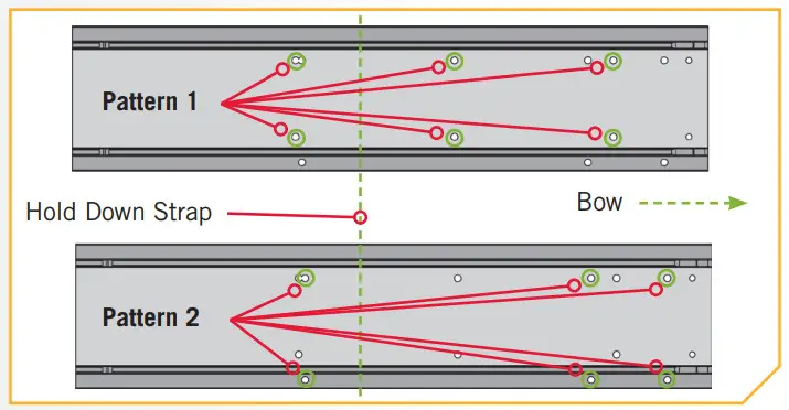
WARNING
When the motor is being transported, on water or land, it is important to place the motor completely out of water. The motor should be positioned up close to the Bowguard. lways secure the Depth Collar Knob for added security during transport and then secure the Hold Down Strap. This provides a secure stow and holds the motor in place during transportation when it is subject to high levels of shock and vibration. Failure to secure the motor may result in injury or damage to the unit.
INSTALLING THE GAS SPRING PIN
ITEM(S) NEEDED

k. Put a 1/4-20 x 2 1/2″ Screw (Item #4) in each of the drilled locations. The Screw should pass through the Mount Plate and the boat deck.
l. Place a Flat Washer (Item #5) and then a Nylock Nut (Item #6) at the end of each screw as shown and secure. Make sure all hardware is secure.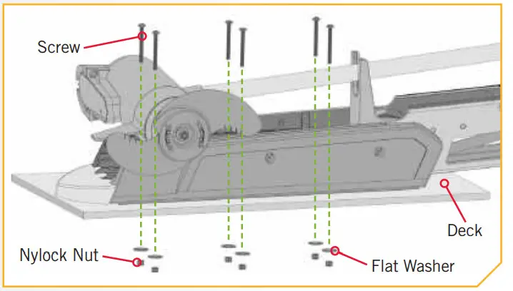 NOTICE: To prevent seizing of the stainless steel hardware, do not use high-speed installation tools. Wetting the screws or applying an anti-seize may help prevent seizing. If possible, secure all sets of mounting bolts, nuts, and washers.
WARNING
The gas assists lift mechanism in this unit is under high spring pressure when the motor is in the deployed position. Do not remove the Bowguard from the mount without disconnecting one end of the gas spring. Failure to do this can create a condition where accidental pulling of the Pull Grip and Rope may cause the mount to spring open rapidly, striking anyone or anything in the direct path.
a. Position the motor to the stowed position with the Pull Grip and Rope to disengage the latch bar, allowing the motor to fold into a flat position.
b. Once in the stowed or flat position, the Gas Spring Pin and Spacers can be installed.
PLACING THE BOW-MOUNT STABILIZER
ITEM(S) NEEDED

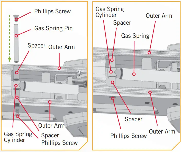
c. Locate the upper Gas Spring Pin (Item #27) and Spacers (Item #26) in the bag assembly. Align the end of the Gas Spring with the holes in the Outer Arm.
d. Install the Gas Spring Pin through the Outer Arm, then through a Spacer, the end of the Gas Spring Cylinder and another Spacer.
e. Install one Phillips Screw (Item #25) on each end of the Gas Spring Pin and secure with two #3 Phillips screwdrivers.
f. Tighten Phillips Screws until the heads are flush with the Outer Arm.
Placing the Bow-Mount Stabilizer
The Bow-Mount Stabilizer Bracket is used to stabilize the Bowguard and reduce bouncing when the motor is stowed and transported. Attention to detail is needed for the successful installation of the stabilizer. We recommend having the stabilizer bracket installed by a qualified marine installer.
NOTICE: The Bow-Mount Stabilizer is not required or included on the 80lb 45” Fortrex.
CAUTION
Adjusting the Aluminum Rod too tightly removes the end play needed for proper latch pin engagement and doing so could prevent the mount from fully latching in the stowed position. Improper latching may cause damage. If installed correctly, the tip of the Aluminum Rod should lift off of the boat deck about 1/4” without the mount unlatching. Cutting the Aluminum Rod too short will cause inadequate support of the mount. Lack of mount support may cause damage.
ITEM(S) NEEDED
![]()
a. Place the motor in the stowed position.
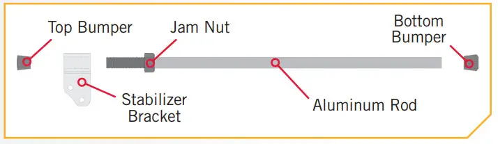
b. Un-thread the Aluminum Rod (Item #13) from the Stabilizer Bracket (Item #12) by removing the Top Bumper (Item #11) and unscrewing the bracket. Also remove the Bottom Bumper (Item #15). Keep the Jam Nut (Item #14) in place.
ITEM(S) NEEDED
![]()
c. Determine the desired orientation of the Stabilizer Bracket and attach it to the bottom of the Bowguard.
NOTICE: The Bow-Mount Stabilizer Bracket can be installed on the left or right side of the Bowguard.
d. Put the 5/16” Cap Screws (Item #17) through the Stabilizer Bracket and the mounting holes on the guard. Secure the 5/16” Cap Screws with the 5/16-18 Nylock Nut. The Nylock Nuts fit into a hex pocket on the inside of the Bowguard behind the spring. Secure with a 1/4” Allen Wrench. Tighten to 10 ft-lb.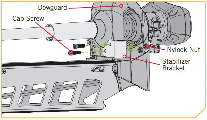
NOTICE: The two Lock Washers (Item #16) are not used when installing on the Fortrex.
e. Measure the proper length of the Aluminum Rod by standing it, with the threaded end down, onto the deck surface so that it sits vertically right next to the Stabilizer Bracket.
f. Mark the Aluminum Rod with a pencil or marker 3/4″ past the top of the Stabilizer Bracket.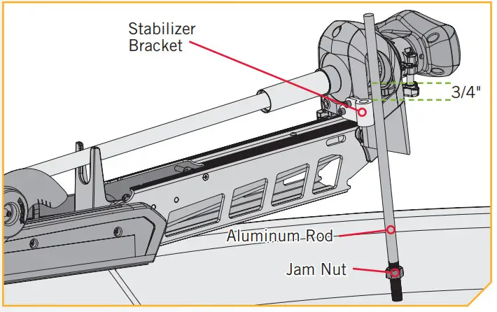 CAUTION
Cutting the Aluminum Rod too short will cause inadequate support of the mount. Lack of mount support may cause damage.
g. Cut the Aluminum Rod with a Hack Saw at the mark. Round the cut edge of the rod with a file or sandpaper to remove any sharp edges.
h. Replace the Bottom Bumper on the Aluminum Rod, opposite from the threads.
i. Thread the Aluminum Rod into the Stabilizer Bracket with the Bottom Bumper towards the boat deck.
j. Adjust the Aluminum Rod up or down in the Stabilizer Bracket so that the Bottom Bumper just touches the support surface.
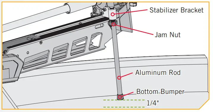
CAUTION
Adjusting the Aluminum Rod too tightly removes the end play needed for proper latch pin engagement and doing so could prevent the mount from fully latching in the stowed position. Improper latching may cause damage. If installed correctly, the tip of the Aluminum Rod should lift off of the boat deck about 1/4” without the mount unlatching.
MOUNTING THE FOOT PEDAL
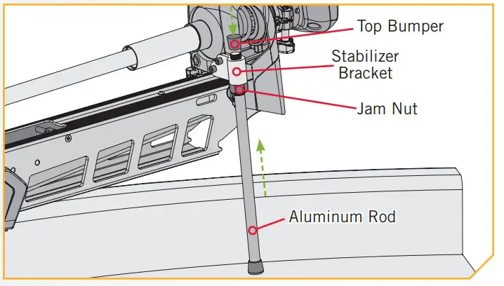
k. Once in the correct position, tighten the Jam Nut upwards against the Stabilizer Bracket. This will prevent the Aluminum Rod from turning.
l. Install the Top Bumper if there are threads exposed on the Aluminum Rod above the Stabilizer Bracket.
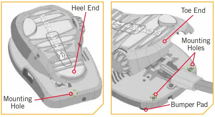
We recommend securing the Foot Pedal to the boat deck to prevent it from being damaged during transport and to make motor operation more efficient. It is recommended to use the Mounting Holes on the Foot Pedal for a secure mount. The Foot The pedal has three Mounting Holes. One Mounting Hole is located under the Heel End of the Foot Pedal. he other two are located under the Toe End of the Foot Pedal. We recommend using a 1/8″ or 3/16″ diameter screw and only tighten enough to slightly compress the Bumper ads underneath the Foot Pedal.
ROUTING CONNECTION CABLES
Please follow these instructions for routing any and all of the cables present for any of the pre-installed features that may come with your trolling motor. This routing should be followed no matter the type of connection cable present.
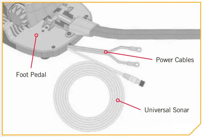
a. Locate the Universal Sonar cable, at the base of the Foot Pedal.CAUTION
Not following the recommended wire routing for Universal Sonar cable, if equipped, may cause damage to the product and void your product warranty. Route cables away from pinch points or other areas that may cause them to bend in sharp angles. Routing the cables in any way other than directed may cause damage to the cables by being pinched or severed.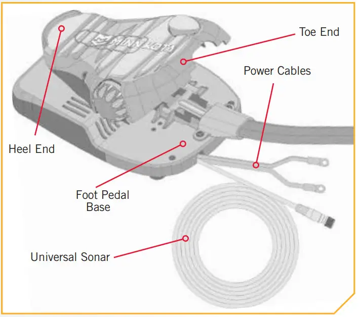 NOTICE: Universal Sonar connector is shown for illustration purposes.
b. Identify where the Universal Sonar Cable needs to be connected and route along with an established routing system in your boat.
c. Use cable ties to loosely secure cables if needed.
NOTICE: After the cable(s) exit(s) the Foot Pedal, it should be routed through an established routing system on the boat, in an area with minimal interference. Power cables or other elements that may produce interference for the sonar signals. Inspect the selected route carefully to ensure that there are no sharp edges, obstacles, or obstructions that may damage the cables.
CAUTION
Improperly securing the Connection Cables may cause damage to the product and void your product warranty. Do not over-tighten the cable ties as it may damage the wires.
UNIVERSAL SONAR
Your trolling motor may be pre-installed with a Universal Sonar transducer system. Universal Sonar is a 2D sonar transducer with a temperature sensor that is integrated into the ower unit of the trolling motor. It has an operating frequency of 83/200 kHz. Connecting this transducer to a compatible fishfinder gives you a 2D sonar view of what is happening directly below your trolling motor. The integrated design protects the transducer from underwater hazards and prevents tangles and damage to the transducer cables. All Universal Sonar motors are equipped with an internal bonding wire, incorrect rigging will cause sonar interference and can damage your trolling motor, electronics and other boat accessories. To minimize trolling motor interference, ensure that the fish finder and trolling motor are powered by separate batteries. Please refer to the Battery & Wiring Installation and Motor Wiring Diagram sections of this manual for correct rigging instructions.
The Universal Sonar Cables are shielded to minimize interference. To protect this shielding the cables should not be pulled tight against sharp angles or hard objects. If using cable ties, do not over-tighten. Any excess cable should be bundled in a loose loop of no less than 4” in diameter. In certain situations, air bubbles may adhere to the surface of the Universal Sonar transducer, and affect the performance. If this happens simply wipe the surface of the transducer with your finger.
NOTICE: Universal Sonar does not support imaging screens that require higher frequencies such as 455 kHz or 800 kHz (Down Imaging, Side Imaging, etc.). Down Imaging (DI) specific units are not compatible with Universal Sonar. See the compatibility chart for a list of compatible fish finders at minnkotamotors.com.
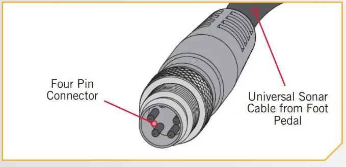
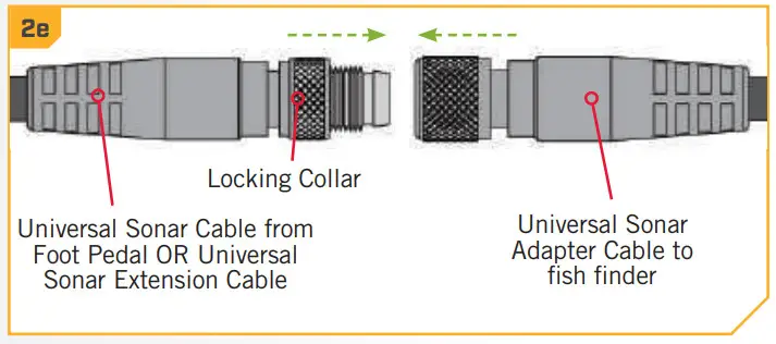
The connector for Universal Sonar exits the trolling motor at the base of the Foot Pedal and consists of a 4 pin plug. An adapter cable (MKR-US2) that is sold separately is required for all installations. For a current list of compatible fish finders and the correct adapter cable, or more information on Universal Sonar, please visit minnkotamotors.com.
a. Locate the Universal Sonar, if equipped, at the base of the Foot Pedal.
b. Locate the Universal Sonar four-pin connector at the end of the Universal Sonar Extension Cable. The connector is black with a stainless steel threaded locking collar.
NOTICE: Your fish finder should be turned off until this procedure is complete.
NOTICE: If the cable length does not reach the desired fish finder installation location, a 14.5’ extension cable is available (MKR-US2-11) (sold separately).
NOTICE: The Universal Sonar Cable may not be long enough to reach the fish finder. If the cable length does not reach the desired fish finder installation location, a 14.5’ extension cable is available to purchase. Minn Kota recommends using the MKR-US2-11.
c. Take the Universal Sonar Extension Cable, if needed, and attach it to the Universal Sonar Cable exiting the Foot Pedal. Firmly push the plug together and twist the locking collar until it is snug.
d. Install the Universal Sonar Cable that exists the Foot Pedal or the Universal Sonar Extension Cable (if used) to the appropriate Universal Sonar Adapter Cable. Install the Adapter Cable to your fishfinder. Refer to your fishfinder manual for complete installation instructions.
NOTICE: If any cables need to be routed, please follow the guidelines in the Routing Connection Cables section of these installation instructions.
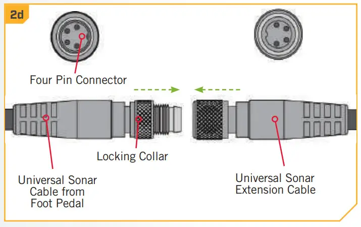
NOTICE: The connectors are keyed to prevent reversed installation.
INSTALLING THE PROP
ITEM(S) NEEDED

CAUTION
Disconnect the motor from the battery before beginning any prop work.
a. Take the Drive Pin (Item #10) and slide it through the Hole in the Armature Shaft. Position the Drive Pin horizontal by grasping the Armature Shaft and rotating it with the Drive Pin in place.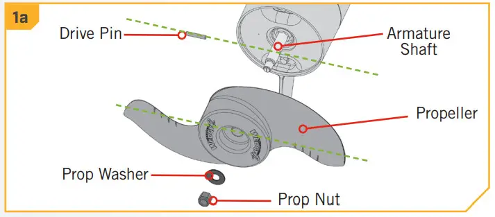 b. Align the Propeller (Item #7) so it is also horizontal and parallel with the Drive Pin. Slide the Propeller onto the Armature Shaft and Drive Pin until it is seated against the lower unit.
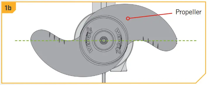
c. Install the Prop Washer (Item #8) and the Prop Nut (Item #9) onto the end of the Armature Shaft.
d. Holding the end of the Armature Shaft with a FlatBlade Screwdriver, tighten the Prop Nut with a 9/16″ Open End Wrench.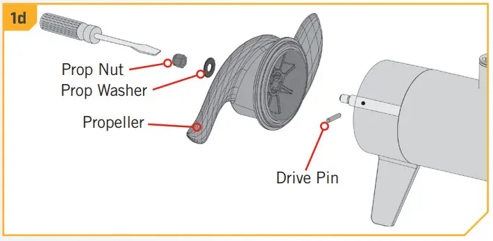 e. Tighten the Prop Nut 1/4 turn past snug to 25-35 in-lbs.CAUTION
Do not overtighten as this can damage the prop.
BATTERY & WIRING INSTALLATION
BOAT RIGGING & PROdUCT INSTALLATION
For safety and compliance reasons, we recommend that you follow American Boat and Yacht Council (ABYC) standards when rigging your boat. Altering boat wiring should be completed by a qualified marine technician. The following specifications are for general guidelines only:CAUTION
These guidelines apply to general rigging to support your Minn Kota motor. Powering multiple motors or additional electrical devices from the same power circuit may impact the recommended conductor gauge and circuit breaker size. If you are using wire longer than that provided with your unit, follow the conductor gauge and circuit breaker sizing table below. If your wire extension length is more than 25 feet, we recommend that you contact a qualified marine technician.CAUTION
An over-current protection device (circuit breaker or fuse) must be used. Coast Guard requirements dictate that each ungrounded current-carrying conductor must be protected by a manually reset, trip-free circuit breaker or fuse. The type (voltage and current rating) of the fuse or circuit breaker must be sized accordingly to the trolling motor used. The table below gives recommended guidelines for circuit breaker sizing.
CONdUCTOR GAUGE ANd CIRCUIT BREAKER SIZING TABLE
This conductor and circuit breaker sizing table are only valid for the following assumptions:
- No more than 2 conductors are bundled together inside of a sheath or conduit outside of engine spaces.
- Each conductor has 105° C temp-rated insulation.
- No more than 5% voltage drop allowed at full motor power based on published product power requirements.
| Motor Thrust / Model | Max Amp Draw | Circuit Breaker | Wire Extension Length | ||||
| 5 feet | 10 feet | 15 feet | 20 feet | 25 feet | |||
| 301b. | 30 | 50 Amp @ 12 VDC | 10 AWG | 10 AWG | 8 AWG | 6 AWG | 4 AWG |
| 40 lb., 451b. | 42 | 10 AWG | 8 AWG | 6 AWG | 4 AWG | 4 AWG | |
| 50 lb., 55 lb. | 50 | 60 Amp @ 12 VDC | 8 AWG | 6 AWG | 4 AWG | 4 AWG | 2 AWG |
| 701b. | 42 | 50 Amp @ 24 VDC | 10 AWG | 10 AWG | 8 AWG | 8 AWG | 6 AWG |
| 801b. | 56 | 60 Amp @ 24 VDC | 8 AWG | 8 AWG | 8 AWG | 6 AWG | 6 AWG |
| 101 lb. | 46 | 50 Amp @ 36 VDC | 8 AWG | 8 AWG | 8 AWG | 8 AWG | 8 AWG |
| Engine Mount 101 | 50 | 60 Amp @ 36 VDC | 8 AWG | 8 AWG | 8 AWG | 8 AWG | 8 AWG |
| 1121b. | 52 | 60 Amp @ 36 VDC | 8 AWG | 8 AWG | 8 AWG | 8 AWG | 8 AWG |
| Engine Mount 160 | 116 | (2) x 60 Amp @ 24 VDC | 6 AWG | 6 AWG | 4 AWG | 2 AWG | 2 AWG |
| E-Drive | 40 | 50 Amp @ 48 VDC | 10 AWG | 10 AWG | 10 AWG | 10 AWG | 10 AWG |
NOTICE: Wire Extension Length refers to the distance from the batteries to the trolling motor leads. Consult the website for available thrust options. Maximum Amp Draw values only occur intermittently during select conditions and should not be used s continuous amp load ratings.
Reference
United States Code of Federal Regulations: 33 CFR 183 – Boats and Associated Equipment ABYC E-11: AC and DC Electrical Systems on Boats
SELECTING THE CORRECT BATTERIES
The motor will operate with any lead-acid, deep cycle marine 12-volt battery/batteries. For best results, use a deep cycle, marine battery with at least a 105 amp-hour rating. Maintain battery at full charge. Proper care will ensure having battery power when you need it, and will significantly improve the battery life. Failure to recharge lead-acid batteries (within 12-24 hours) is the leading cause of premature battery failure. Use a multi-stage charger to avoid overcharging. We offer a wide selection of chargers to fit your charging needs. If you are using a crank battery to start a gasoline outboard, we recommend that you use a separate deep cycle marine battery/batteries for your Minn Kota trolling motor. For more information on battery selection and rigging, please visit minnkotamotors.com. Minn Kota trolling motors can run on Lithium-Ion batteries. However, they are specifically designed to run on traditional lead-acid batteries (flooded, AMG, or GEL). Lithium-Ion batteries maintain higher voltages for longer periods of time than lead-acid. Therefore, running a Minn Kota trolling motor at speeds higher than 85% for a prolonged period could cause permanent damage to the motor.WARNING
Never connect the (+) and the (–) terminals of the same battery together. Take care that no metal object can fall onto the battery and short the terminals. This would immediately lead to short and extreme fire danger.CAUTION
Refer to “Conductor Gauge and Circuit Breaker Sizing Table” in the previous section to find the appropriate circuit breaker or fuse for your motor. For motors requiring a 60-amp breaker, the Minn Kota MKR-19 60-amp circuit breaker is recommended.CAUTION
Please read the following information before connecting your motor to your batteries in order to avoid damaging your motor and/or voiding your warranty.
AddITIONAL CONSIdERATIONS
Using Alternator Chargers
Your Minn Kota trolling motor may be designed with an internal bonding wire to reduce sonar interference. Most alternator charging systems do not account for this bonding wire and connect the negative posts of the trolling motor batteries to the negative posts of the crank/starting battery. These external connections can damage connected electronics and the electrical system of your trolling motor, voiding your warranty. Review your charger’s manual carefully or consult the manufacturer prior to use to ensure your charger is compatible. Minn Kota recommends using Minn Kota brand chargers to recharge the batteries connected to your Minn Kota trolling motor, as they have been engineered to work with motors that include a bonding wire.
Additional Accessories Connected to Trolling Motor Batteries
Significant damage to your Minn Kota motor, your boat electronics, and your boat can occur if incorrect connections are made between your trolling motor batteries and other battery systems. Minn Kota recommends using an exclusive battery system for your trolling motor. Where possible, accessories should be connected to a separate battery system. Radios and sonar units should not be connected to any trolling motor battery systems as interference from the trolling motor is unavoidable. If connecting any additional accessories to any trolling motor battery system, or making connections between the trolling motor batteries and other battery systems on the boat, be sure to carefully observe the information below.
CONNECTING THE BATTERIES IN SERIES
The negative (-) connection must be connected to the negative terminal of the same battery that the trolling motor negative lead connects to. In the diagrams below this battery is labeled “Low Side” Battery. Connecting to any other trolling motor battery will input positive voltage into the “ground” of that accessory, which can cause excessive corrosion. Any damage caused by incorrect connections between battery systems will not be covered under warranty.
Automatic Jump Start Systems and Selector Switches
Automatic jump start systems and selector switches tie the negatives of the connected batteries together. Connecting these systems to the “High Side” Battery or “Middle” Battery in the diagrams below and will cause significant damage to your trolling motor and electronics. The only trolling motor battery that is safe to connect to one of these systems is the “Low Side” Battery.
NOTICE: The internal bonding wire is equipped with a 3 amp fuse. Improper connections described above carrying in excess of 3 amps will blow this fuse and no further damage will be exhibited. If this occurs, RF interference from the trolling motor affecting sonar units and other electronics will be more significant. If the fuse is blown the wiring error should be found and addressed prior to replacing the fuse. The replacement fuse should be 3 amps or less. An intact fuse does not imply correct rigging; significant damage can be done by incorrect wiring without approaching 3 amps of current.
CONNECTING THE BATTERIES IN SERIES (IF REQUIREd FOR YOUR MOTOR)
24 Volt Systems
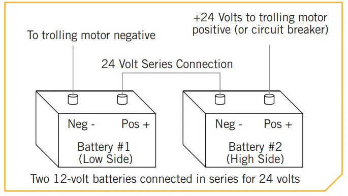
Two 12 volt batteries are required. The batteries must be wired in series, only as directed in a wiring diagram, to provide 24 volts.
- Make sure that the motor is switched off (speed selector on “0”).
- Connect a connector cable to the positive ( + ) terminal of battery 1 and to the negative ( – ) terminal of battery 2.
- Connect positive ( + ) red motor lead to positive ( + ) terminal on battery 2.
- Connect negative ( – ) black motor lead to negative ( – ) the terminal of battery 1.
WARNING
For safety reasons do not switch the motor on until the propeller is in the water. If installing a lead wire plug, observe proper polarity and follow instructions in your boat owner’s manual.WARNING
- For safety reasons, disconnect the motor from the battery or batteries when the motor is not in use or while the battery/batteries are being charged.
- Improper wiring of 24/36 volt systems could cause battery explosion.
- Keep lead wire wing nut connections tight and solid to battery terminals.
- Locate the battery in a ventilated compartment.
36 Volt Systems
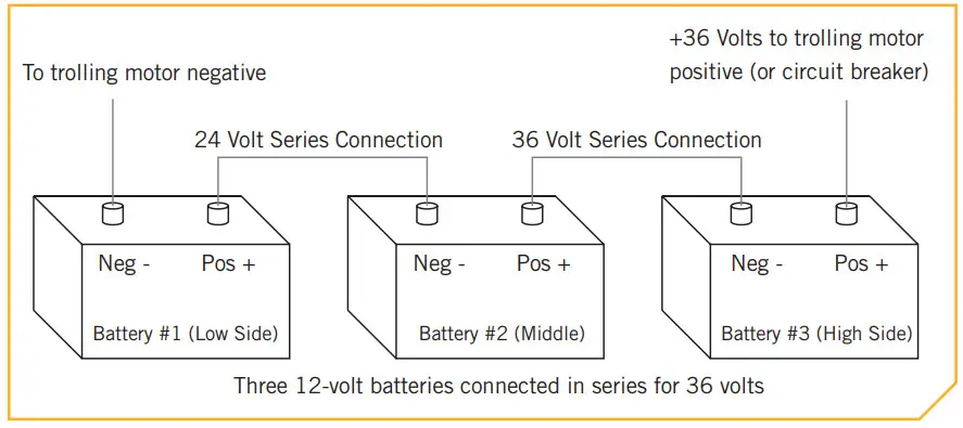 Three 12 volt batteries are required. The batteries must be wired in series, only as directed in a wiring diagram, to provide 36 volts.
- Make sure that the motor is switched off (speed selector on “0”).
- Connect a connector cable to the positive ( + ) terminal of battery 1 and to the negative ( – ) terminal of battery 2 and another connector cable from the positive ( + ) terminal of battery 2 to the negative ( – ) terminal of battery 3.
- Connect positive ( + ) red motor lead to positive ( + ) terminal on battery 3.
- Connect negative ( – ) black motor lead to negative ( – ) terminal of battery 1.
WARNING
For safety reasons do not switch the motor on until the propeller is in the water. If installing a lead wire plug, observe proper polarity and follow instructions in your boat owner’s manual.WARNING
- For safety reasons, disconnect the motor from the battery or batteries when the motor is not in use or while the battery/batteries are being charged.
- Improper wiring of 24/36 volt systems could cause battery explosion.
- Keep lead wire wing nut connections tight and solid to battery terminals.
- Locate the battery in a ventilated compartment.
This completes the installation of your Fortrex. A Complete Owner’s Manual can be downloaded at minnkotamotors.com.
NOTES
_______________________________________________
_______________________________________________
________________________________________________
RECOMMENDED ACCESSORIES
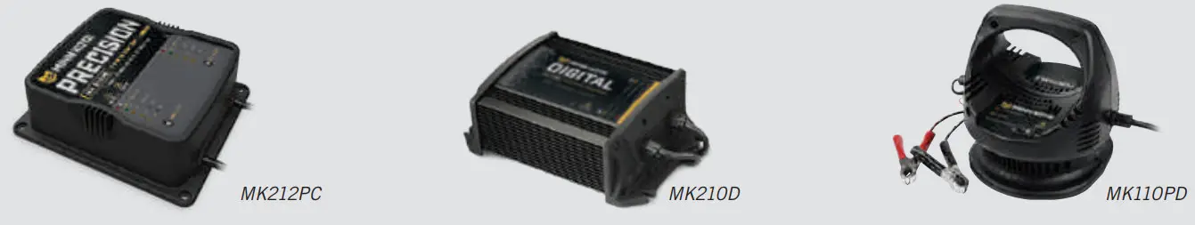
ON-BOARd & PORTABLE BATTERY CHARGERS
Stop buying new batteries and start taking care of the ones you’ve got. Many chargers can actually damage your battery over time – creating shorter run times and shorter overall life. Digitally controlled Minn Kota chargers are designed to provide the fastest charge that protects and extends battery life.
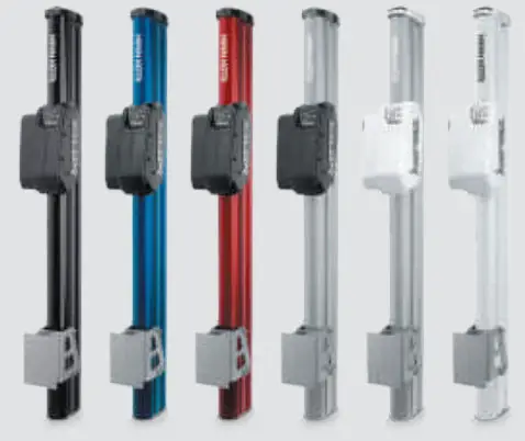
TALON SHALLOW WATER ANCHOR
Introducing the all-new, sleek redesigned Talon. Talon is the only shallow water anchor with up to 15’ of anchoring depth, multiple anchoring modes, and control from the bow, transom, console, remote or mobile device.
BUILT-IN WORK LIGHT Let’s you tie lines and work from the transom any time of day — or night. Includes both white and blue LED lights with three brightness settings. BLUETOOTH®
CONNECTIVITY Let’s you control Talon from your mobile device and easily update it. Also opens up communication to other control options.
UP TO 15’ dEEP Control more water and catch more fish with the first 15’ shallow water anchor.
MORE CONTROL OPTIONS

- Control Panel
- Wireless Remote
- Mobile App
- Wireless Foot Switch
- Humminbird® Connectivity
- i-Pilot®& i-Pilot Link ™Remote
MINN KOTA ACCESSORIES
We offer a wide variety of trolling motor accessories, including:
| • 60-Amp Circuit Breaker • Mounting Brackets • Stabilizer Kits • Extension Handles | • Battery Connectors • Battery Boxes • Quick Connect Plugs |
![]()

minnkotamotors.com
Part #2287110
Minn Kota Consumer & Technical Service Johnson Outdoors Marine Electronics, Inc. PO Box 8129
Mankato, MN 56001
121 Power Drive Mankato, MN 56001
Phone (800) 227-6433
Fax (800) 527-4464
©2021 Johnson Outdoors Marine Electronics, Inc.
All rights reserved.


