Zennio ZCL8H230V2 8/6/2 Output 230V Heating Actuator
Product Information
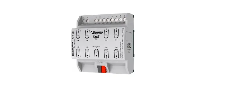
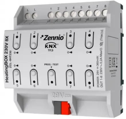
Heating BOX 230V 8X/6X/2X v2
Heating BOX 230V 8X/6X/2X v2 from Zennio is a heating specific KNX actuator equipped with 8 / 6 / 2 independent outputs (depending on the model) for controlling 230V valves. It is designed for controlling electromechanical valves and offers several outstanding features:
- 8 / 6 / 2 configurable outputs for controlling valves
- 8 / 6 / 2 multi-purpose inputs, configurable as temperature probes or binary inputs (pushbuttons, switches, sensors)
- A sole 230 VAC power input for all outputs
- 8 / 6 / 2 independent thermostats
- 10 customizable, multi-operation logic functions
- Manual operation / supervision of the outputs through the on-board pushbuttons and LEDs
- Heartbeat or periodical still-alive notification
Product Usage Instructions
To start using the HeatingBOX 230V 8X/6X/2X v2, please follow the steps below:
Start-up and Power Loss
During the start-up, the device may perform specific actions based on its configuration. Consult the user manual for details on configuring the device’s behavior during start-up. In case of a bus power failure, the device will interrupt pending actions and save its state to be recovered once power is restored.
Configuration
To configure the HeatingBOX 230V 8X/6X/2X v2, follow these steps:
- Import the corresponding database in ETS (Engineering Tool Software).
- Add the device into the topology of the desired project.
- Access the Parameters tab of the device to begin the configuration process.
After importing the corresponding database in ETS and adding the device into the topology of the desired project, the configuration process begins by entering the Parameters tab of the device.
General Configuration
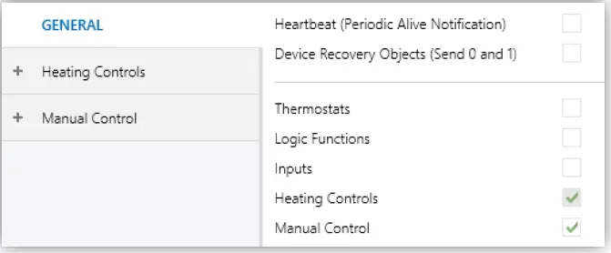
In the General screen, you can activate or deactivate the required functionality. The following parameter is available:
- Heartbeat (Periodic Alive Notification): This parameter allows the integrator to incorporate a one-bit object to the project ([Heartbeat] Object to Send `1′) that will be sent periodically with value 1 to notify that the device is still working (still alive).
From the “General” screen it is possible to activate/deactivate all the required functionality.
ETS PARAMETERISATION
General screen
- Heartbeat (Periodic Alive Notification) [disabled/enabled]1: this parameter lets the integrator incorporate a one-bit object to the project (“[Heartbeat] Object to Send ‘1’”) that will be sent periodically with value “1” to notify that the device is still working (still alive).

Heartbeat (Periodical Alive Notification).
1 The default values of each parameter will be highlighted in blue in this document, as follows: [default/rest of options].
Note: the first sending after download or bus failure takes place with a delay of up to 255 seconds, to prevent bus overload. The following sendings match the period set.
Device Recovery Objects (Send 0 and 1) [disabled/enabled]: this parameter lets the integrator activate two new communication objects (“[Heartbeat] Device Recovery”), which will be sent to the KNX bus with values “0” and “1” respectively whenever the device begins operation (for example, after a bus power failure). It is possible to parameterise a certain delay [0…255] to his sending.

Sending of Indication objects on bus voltage recovery.
Note: After download or bus failure, the sending takes place with a delay of up to 6,35 seconds plus the parameterised delay, to prevent overload.
- Thermostats [disabled/enabled]: enables or disables the “Thermostats” tab in the tree on the left. See section 2.2 for details.
- Logic Function [disabled/enabled]: enables or disables the “Logic Functions” tab in the tree on the left. See section 2.3 for details.
- Inputs [disabled/enabled]: enables or disables the “Inputs” tab in the tree on the left. See section 2.4 for details.
- Heating Controls [enabled]: read-only parameter to make it evident that the “Heating Controls” tab is always enabled in the tab tree on the left. See section 2.5 for details.
- Manual Control [disabled/enabled]: enables or disables the “Manual Control” tab in the tree on the left. See section 2.6 for details.
THERMOSTATS
HeatingBOX implements 8 / 6 / 2 Zennio thermostats (depending on the model) which can be enabled and configured independently. Please refer to the specific “Zennio Thermostat” user manual (available in the product section at the Zennio homepage, www.zennio.com) for detailed information about the functionality and the configuration of the related parameters.
LOGIC FUNCTIONS
This module makes it possible to perform numeric and binary operations to incoming values received from the KNX bus, and to send the results through other communication objects specifically enabled for this purpose. HeatingBOX can implement up to 10 different and independent functions, each of them entirely customisable and consisting in up to 4 consecutive operations each one. The execution of each function can depend on a configurable condition, which will be evaluated every time the function is triggered through specific, parameterisable communication objects. The result after executing the operations of the function can also be evaluated according to certain conditions and afterwards sent (or not) to the KNX bus, which can be done every time the function is executed, periodically or only when the result differs from the last one. Please refer to the specific “Logic Functions” user manual (available in the product section at the Zennio homepage, www.zennio.com) for detailed information about the functionality and the configuration of the related parameters.
INPUTS
HeatingBOX incorporates 8 / 6 / 2 analogue/digital inputs, each configurable as a:
- Binary Inputs, for the connection of a pushbutton or a switch/sensor.
- Temperature Probe, to connect a temperature sensor from Zennio or NTC probes from third parties (the latter requires configuring their parameters in ETS).
BINARY INPUTS
Please refer to the specific user manual “Binary Inputs”, available in the product section, at the Zennio website (www.zennio.com).
TEMPERATURE PROBE
Please refer to the specific user manual “Temperature Probe”, available in the product section, at the Zennio website (www.zennio.com).
HEATING CONTROLS
The HeatingBOX actuator incorporates 8 / 6 / 2 outputs, each of them capable of controlling one or several heating valves at 230V. Please refer to the specific “Heating Control” user manual (available in the product section at the Zennio homepage, www.zennio.com) for detailed information about the functionality and the configuration of the related parameters.
MANUAL CONTROL
HeatingBOX allows controlling the outputs through the pushbuttons on the top of the device. Each output has its associated pushbutton. Manual operation can be done in two different ways, named as Test On Mode (for testing purposes during the configuration of the device) and Test Off Mode (for a normal use, anytime). Whether both, only one or none of these modes are available needs to be parameterised in ETS. Moreover, it is possible to enable a specific binary object for locking and unlocking the manual control in runtime.
Note:
- The Test Off mode will be active (unless it has been disabled by parameter) after a download or a reset with no need of a specific activation – the pushbuttons will respond to user presses from the start.
- On the contrary, switching to the Test On mode (unless disabled by parameter) needs to be done by long-pressing the Prog./Test button (for at least three seconds), until the LED is no longer red and turns yellow. From that moment, once the button is released, the LED light will remain green to confirm that the device has switched from the Test Off mode to the Test On mode. After that, an additional press will turn the LED yellow and then off, once the button is released. This way, the device leaves the Test On mode. Note that it will also leave this mode if a bus power failure takes place.
- The manual control of the outputs is intended to perform on/off switches, independently of the method of control configured (one-bit or one-byte). In other words, it does allow testing the opening and closing of the valves, but intermediate positioning is not possible.
Test Off Mode
Under the Test Off Mode, the outputs can be controlled through both their communication objects and the actual pushbuttons located on the top of the device. Also, during this manual control mode, the control commands received by the bus will continue to be analysed and executed. If the pushbutton on an enabled output is pressed, the output will behave as if an order to open or to close the valve had been received through the corresponding communication object and will also send the status objects when required. Regarding the lock and alarm functions, the device will behave under the Test Off mode as usual. Button presses during this mode are entirely analogous to the reception of the corresponding orders from the KNX bus.
Test On Mode
After entering the Test On mode, it will only be possible to control the outputs through the on-board pushbuttons. Control orders received through communication objects will be ignored. Short or long pressing the button will commute the on-off state of the output. The LED will light in green while the button is being hold. The lock and alarm functions as well as any orders received from the KNX bus will not have an effect over the output status while the device is under the Test On mode. The status objects will not be sent to the bus, either. On the contrary, the alarm and lock objects will be re-evaluated after leaving the Test On mode, so any changes that may have taken place in Test On will be considered when leaving.
Important: the device is delivered from factory with both manual modes (Test Off and Test On) enabled by default.
For detailed technical features, installation process, and security procedures, please refer to the Datasheet provided with the original packaging of the device or visit www.zennio.com.
If you need further assistance or technical support, visit https://support.zennio.com/.
DOCUMENT UPDATES
| Version | Changes | Page(s) |
| [1.5]_b | New devices: HeatingBOX 230V 6X / 2X v2. | – |
INTRODUCTION
HeatingBOX
HeatingBOX from Zennio is a heating specific KNX actuator equipped, with 8 / 6 / 2 independent outputs (depending on the model) for controlling 230V valves.
The most outstanding features are:
- / 6 / 2 configurable outputs for controlling electromechanical valves.
- 8 / 6 / 2 multi-purpose inputs, configurable as:
- Temperature probe (with the possibility to parameterize a personalized probe).
- Binary inputs (i.e., pushbuttons, switches, sensors).
- A sole 230 VAC power input for all outputs.
- 8 / 6 / 2 independent thermostats.
- 10 customisable, multi-operation logic functions.
- Manual operation / supervision of the outputs through the on-board pushbuttons and LEDs.
- Heartbeat or periodical “still-alive” notification.
START-UP AND POWER LOSS
During the start-up of the device and depending on the configuration, some specific actions may be performed. For example, the integrator can set whether the outputs should change to a particular position and whether the device should send certain objects to the bus after the power recovery. Please consult the next sections of this document for further details. On the other hand, when a bus power failure takes place, the device will interrupt any pending actions, and will save its state so it can be recovered once the power supply is restored. To get detailed information about the technical features of this device, as well as on the installation process and on security procedures, please refer to the corresponding Datasheet, bundled with the original packaging of the device and also available at www.zennio.com.
ETS PARAMETERISATION
After enabling “Manual Control” in the Configuration screen (see section 2.1), a new tab will be incorporated into the tab tree on the left.
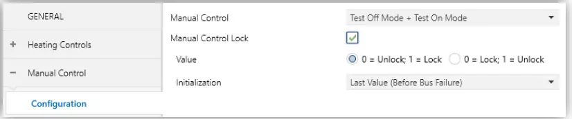
Manual Control.
The only two parameters are:
- Mode [Disabled / Only with Test Mode Off / Only with Test Mode On / Test Off Mode + Test On Mode]. Depending on the selection, the device will permit using the manual control under the Test Off, the Test On, or both modes. Note that, as stated before, using the Test Off mode does not require any special action, while switching to the Test On mode does require long-pressing the Prog./Test button.
- Lock Manual Control [disabled/enabled]: unless the above parameter has been “Disabled”, the Lock Manual Control parameter provides an optional procedure for locking the manual control in runtime. When this checkbox is enabled, object “Lock Manual Control” turns visible, as well as two more parameters:
- Value [0 = Unlock; 1 = Lock / 0 = Lock; 1= Unlock]: defines whether the manual control lock/unlock should take place respectively upon the reception (through the aforementioned object) of values “0” and “1”, or the opposite.
- Initialization [Unlocked / Locked / Last Value (Before Bus Failure)]: sets how the manual control should remain after the device start-up (after an ETS download or a bus power failure).
ANNEX I. COMMUNICATION OBJECTS
- “Functional range” shows the values that, with independence of any other values permitted by the bus according to the object size, may be of any use or have a particular meaning because of the specifications or restrictions from both the KNX standard or the application programme itself.’
| Number | Size | I/O | Flags | Data type (DPT) | Functional Range | Name | Function |
| 1 | 1 Bit | I | C – W – – | DPT_Switch | 0/1 | Lock Manual Control | 0 = Unlock; 1 = Lock |
| 1 Bit | I | C – W – – | DPT_Switch | 0/1 | Lock Manual Control | 0 = Lock; 1 = Unlock | |
| 2 | 1 Byte | I | C – W – – | DPT_SceneControl | 0-63; 128-191 | [Thermostat] Scenes | 0 – 63 (Execute 1 – 64); 128 – 191 (Save 1 – 64) |
| 3, 41, 79, 117, 155, 193, 231, 269 | 2 Bytes | I | C – W T U | DPT_Value_Temp | -273,00º – 670433,28º | [Tx] Temperature Source 1 | External Sensor Temperature |
| 4, 42, 80, 118, 156, 194, 232, 270 | 2 Bytes | I | C – W T U | DPT_Value_Temp | -273,00º – 670433,28º | [Tx] Temperature Source 2 | External Sensor Temperature |
| 5, 43, 81, 119, 157, 195, 233, 271 | 2 Bytes | O | C R – T – | DPT_Value_Temp | -273,00º – 670433,28º | [Tx] Effective Temperature | Effective Control Temperature |
| 6, 44, 82, 120, 158, 196, 234, 272 | 1 Byte | I | C – W – – | DPT_HVACMode | 1=Confort 2=Standby 3=Económico 4=Protección | [Tx] Special Mode | 1-Byte HVAC Mode |
| 7, 45, 83, 121, 159, 197, 235, 273 | 1 Bit | I | C – W – – | DPT_Ack | 0/1 | [Tx] Special Mode: Comfort | 0 = Nothing; 1 = Trigger |
| 1 Bit | I | C – W – – | DPT_Switch | 0/1 | [Tx] Special Mode: Comfort | 0 = Off; 1 = On | |
| 8, 46, 84, 122, 160, 198, 236, 274 | 1 Bit | I | C – W – – | DPT_Ack | 0/1 | [Tx] Special Mode: Standby | 0 = Nothing; 1 = Trigger |
| 1 Bit | I | C – W – – | DPT_Switch | 0/1 | [Tx] Special Mode: Standby | 0 = Off; 1 = On | |
| 9, 47, 85, 123, 161, 199, 237, 275 | 1 Bit | I | C – W – – | DPT_Ack | 0/1 | [Tx] Special Mode: Economy | 0 = Nothing; 1 = Trigger |
| 1 Bit | I | C – W – – | DPT_Switch | 0/1 | [Tx] Special Mode: Economy | 0 = Off; 1 = On | |
| 10, 48, 86, 124, 162, 200, 238, 276 | 1 Bit | I | C – W – – | DPT_Ack | 0/1 | [Tx] Special Mode: Protection | 0 = Nothing; 1 = Trigger |
| 1 Bit | I | C – W – – | DPT_Switch | 0/1 | [Tx] Special Mode: Protection | 0 = Off; 1 = On | |
| 11, 49, 87, 125, 163, 201, 239, 277 | 1 Bit | I | C – W – – | DPT_Window_Door | 0/1 | [Tx] Window Status (Input) | 0 = Closed; 1 = Open |
| 12, 50, 88, 126, 164, 202, 240, 278 | 1 Bit | I | C – W – – | DPT_Trigger | 0/1 | [Tx] Comfort Prolongation | 0 = Nothing; 1 = Timed Comfort |
| 13, 51, 89, 127, 165, 203, 241, 279 | 1 Byte | O | C R – T – | DPT_HVACMode | 1=Confort 2=Standby 3=Económico 4=Protección | [Tx] Special Mode Status | 1-Byte HVAC Mode |
| 2 Bytes | I | C – W – – | DPT_Value_Temp | -273,00º – 670433,28º | [Tx] Setpoint | Thermostat Setpoint Input |
| 14, 52, 90, 128, 166, 204, 242, 280 | 2 Bytes | I | C – W – – | DPT_Value_Temp | -273,00º – 670433,28º | [Tx] Basic Setpoint | Reference Setpoint |
| 15, 53, 91, 129, 167, 205, 243, 281 | 1 Bit | I | C – W – – | DPT_Step | 0/1 | [Tx] Setpoint Step | 0 = Decrease Setpoint; 1 = Increase Setpoint |
| 16, 54, 92, 130, 168, 206, 244, 282 | 2 Bytes | I | C – W – – | DPT_Value_Tempd | -671088,64º – 670433,28º | [Tx] Setpoint Offset | Float Offset Value |
| 17, 55, 93, 131, 169, 207, 245, 283 | 2 Bytes | O | C R – T – | DPT_Value_Temp | -273,00º – 670433,28º | [Tx] Setpoint Status | Current Setpoint |
| 18, 56, 94, 132, 170, 208, 246, 284 | 2 Bytes | O | C R – T – | DPT_Value_Temp | -273,00º – 670433,28º | [Tx] Basic Setpoint Status | Current Basic Setpoint |
| 19, 57, 95, 133, 171, 209, 247, 285 | 2 Bytes | O | C R – T – | DPT_Value_Tempd | -671088,64º – 670433,28º | [Tx] Setpoint Offset Status | Current Setpoint Offset |
| 20, 58, 96, 134, 172, 210, 248, 286 | 1 Bit | I | C – W – – | DPT_Reset | 0/1 | [Tx] Setpoint Reset | Reset Setpoint to Default |
| 1 Bit | I | C – W – – | DPT_Reset | 0/1 | [Tx] Offset Reset | Reset Offset | |
| 21, 59, 97, 135, 173, 211, 249, 287 | 1 Bit | I | C – W – – | DPT_Heat_Cool | 0/1 | [Tx] Mode | 0 = Cool; 1 = Heat |
| 22, 60, 98, 136, 174, 212, 250, 288 | 1 Bit | O | C R – T – | DPT_Heat_Cool | 0/1 | [Tx] Mode Status | 0 = Cool; 1 = Heat |
| 23, 61, 99, 137, 175, 213, 251, 289 | 1 Bit | I | C – W – – | DPT_Switch | 0/1 | [Tx] On/Off | 0 = Off; 1 = On |
| 24, 62, 100, 138, 176, 214, 252, 290 | 1 Bit | O | C R – T – | DPT_Switch | 0/1 | [Tx] On/Off Status | 0 = Off; 1 = On |
| 25, 63, 101, 139, 177, 215, 253, 291 | 1 Bit | I/O | C R W – – | DPT_Switch | 0/1 | [Tx] Main System (Cool) | 0 = System 1; 1 = System 2 |
| 26, 64, 102, 140, 178, 216, 254, 292 | 1 Bit | I/O | C R W – – | DPT_Switch | 0/1 | [Tx] Main System (Heat) | 0 = System 1; 1 = System 2 |
| 27, 65, 103, 141, 179, 217, 255, 293 | 1 Bit | I | C – W – – | DPT_Enable | 0/1 | [Tx] Enable/Disable Secondary System (Cool) | 0 = Disable; 1 = Enable |
| 28, 66, 104, 142, 180, 218, 256, 294 | 1 Bit | I | C – W – – | DPT_Enable | 0/1 | [Tx] Enable/Disable Secondary System (Heat) | 0 = Disable; 1 = Enable |
| 29, 35, 67, 73, 105, 111, 143, 149, 181, 187, 219, 225, 257, 263, 295, 301 | 1 Byte | O | C R – T – | DPT_Scaling | 0% – 100s | [Tx] [Sx] Control Variable (Cool) | PI Control (Continuous) |
| 30, 36, 68, 74, 106, 112, 144, 150, 182, 188, 220, 226, 258, 264, 296, 302 | 1 Byte | O | C R – T – | DPT_Scaling | 0% – 100% | [Tx] [Sx] Control Variable (Heat) | PI Control (Continuous) |
| 1 Byte | O | C R – T – | DPT_Scaling | 0% – 100% | [Tx] [Sx] Control Variable | PI Control (Continuous) | |
| 31, 37, 69, 75, 107, 113, 145, 151, 183, 189, 221, 227, 259, 265, 297, 303 | 1 Bit | O | C R – T – | DPT_Switch | 0/1 | [Tx] [Sx] Control Variable (Cool) | 2-Point Control |
| 1 Bit | O | C R – T – | DPT_Switch | 0/1 | [Tx] [Sx] Control Variable (Cool) | PI Control (PWM) | |
| 1 Bit | O | C R – T – | DPT_Switch | 0/1 | [Tx] [Sx] Control Variable (Heat) | 2-Point Control |
| 32, 38, 70, 76, 108, 114, 146, 152, 184, 190, 222, 228, 260, 266, 298, 304 | 1 Bit | O | C R – T – | DPT_Switch | 0/1 | [Tx] [Sx] Control Variable (Heat) | PI Control (PWM) |
| 1 Bit | O | C R – T – | DPT_Switch | 0/1 | [Tx] [Sx] Control Variable | 2-Point Control | |
| 1 Bit | O | C R – T – | DPT_Switch | 0/1 | [Tx] [Sx] Control Variable | PI Control (PWM) | |
| 33, 39, 71, 77, 109, 115, 147, 153, 185, 191, 223, 229, 261, 267, 299, 305 | 1 Bit | O | C R – T – | DPT_Switch | 0/1 | [Tx] [Sx] PI State (Cool) | 0 = PI Signal 0%; 1 = PI Signal Greater than 0% |
| 34, 40, 72, 78, 110, 116, 148, 154, 186, 192, 224, 230, 262, 268, 300, 306 | 1 Bit | O | C R – T – | DPT_Switch | 0/1 | [Tx] [Sx] PI State (Heat) | 0 = PI Signal 0%; 1 = PI Signal Greater than 0% |
| 1 Bit | O | C R – T – | DPT_Switch | 0/1 | [Tx] [Sx] PI State | 0 = PI Signal 0%; 1 = PI Signal Greater than 0% | |
| 307, 308, 309, 310, 311, 312, 313, 314, 315, 316, 317, 318, 319, 320, 321, 322, 323, 324, 325, 326, 327, 328, 329, 330, 331, 332, 333, 334, 335, 336, 337, 338 | 1 Bit | I | C – W – – | DPT_Bool | 0/1 | [LF] (1-Bit) Data Entry x | Binary Data Entry (0/1) |
| 339, 340, 341, 342, 343, 344, 345, 346, 347, 348, 349, 350, 351, 352, 353, 354 | 1 Byte | I | C – W – – | DPT_Value_1_Ucount | 0 – 255 | [LF] (1-Byte) Data Entry x | 1-Byte Data Entry (0-255) |
| 355, 356, 357, 358, 359, 360, 361, 362, 363, 364, 365, 366, 367, 368, 369, 370 | 2 Bytes | I | C – W – – | DPT_Value_2_Ucount | 0 – 65535 | [LF] (2-Byte) Data Entry x | 2-Byte Data Entry |
| 371, 372, 373, 374, 375, 376, 377, 378 | 4 Bytes | I | C – W – – | DPT_Value_4_Count | -2147483648 – 2147483647 | [LF] (4-Byte) Data Entry x | 4-Byte Data Entry |
| 379, 380, 381, 382, 383, 384, 385, 386, 387, 388 | 1 Bit | O | C R – T – | DPT_Bool | 0/1 | [LF] Function x – Result | (1-Bit) Boolean |
| 1 Byte | O | C R – T – | DPT_Value_1_Ucount | 0 – 255 | [LF] Function x – Result | (1-Byte) Unsigned | |
| 2 Bytes | O | C R – T – | DPT_Value_2_Ucount | 0 – 65535 | [LF] Function x – Result | (2-Byte) Unsigned | |
| 4 Bytes | O | C R – T – | DPT_Value_4_Count | -2147483648 – 2147483647 | [LF] Function x – Result | (4-Byte) Signed | |
| 1 Byte | O | C R – T – | DPT_Scaling | 0% – 100% | [LF] Function x – Result | (1-Byte) Percentage | |
| 2 Bytes | O | C R – T – | DPT_Value_2_Count | -32768 – 32767 | [LF] Function x – Result | (2-Byte) Signed | |
| 2 Bytes | O | C R – T – | 9.xxx | -671088,64 – 670433,28 | [LF] Function x – Result | (2-Byte) Float | |
| 389 | 1 Bit | O | C R – T – | DPT_Bool | 0/1 | [HC] All Valves Are Closed | 0 = False; 1 = True |
| 1 Bit | O | C R – T – | DPT_Bool | 0/1 | [HC] All Valves Are Closed | 0 = True; 1 = False | |
| 390 | 1 Byte | O | C R – T – | DPT_Scaling | 0% – 100% | [HC] Max. Control Value (Output) | 0 – 100 % |
| 391 | 1 Byte | I | C – W – – | DPT_Scaling | 0% – 100% | [HC] Max. Control Value (Input) | 0 – 100 % |
| 392, 404, 416, 428, 440, 452, 464, 476 | 1 Bit | O | C R – T – | DPT_Alarm | 0/1 | [HCx] Short Circuit Error | 0 = No Error; 1 = Error |
| 393, 441 | 1 Bit | O | C R – T – | DPT_Alarm | 0/1 | [HCx-x] Overload Error | 0 = No Error; 1 = Error |
| 394, 406, 418, 430, 442, 454, 466, 478 | 1 Bit | I | C – W – – | DPT_Enable | 0/1 | [HCx] Lock | 0 = Unlock; 1 = Lock |
| 395, 407, 419, 431, 443, 455, 467, 479 | 1 Bit | I | C – W – – | DPT_Alarm | 0/1 | [HCx] Alarm | 0 = No Alarm; 1 = Alarm |
| 1 Bit | I | C – W – – | DPT_Alarm | 0/1 | [HCx] Alarm | 0 = Alarm; 1 = No Alarm | |
| 396, 408, 420, 432, 444, 456, 468, 480 | 1 Bit | I | C – W – – | DPT_Alarm | 0/1 | [HCx] Alarm x | 0 = No Alarm; 1 = Alarm |
| 1 Bit | I | C – W – – | DPT_Alarm | 0/1 | [HCx] Alarm x | 0 = Alarm; 1 = No Alarm | |
| 397, 409, 421, 433, 445, 457, 469, 481 | 1 Bit | I | C – W – – | DPT_Ack | 0/1 | [HCx] Unfreeze Alarm | Alarm = No Alarm + Unfreeze (1) -> End Alarm |
| 1 Bit | I | C – W – – | DPT_Ack | 0/1 | [HCx] Unfreeze Alarm | Alarm = Alarm 2 = No Alarm + Unfreeze (1) -> End Alarm | |
| 398, 410, 422, 434, 446, 458, 470, 482 | 1 Bit | O | C R – T – | DPT_Bool | 0/1 | [HCx] Control Value – Error | 0 = No Error; 1 = Error |
| 399, 411, 423, 435, 447, 459, 471, 483 | 1 Bit | O | C R – T – | DPT_State | 0/1 | [HCx] Anti-Seize Protection | 0 = Inactive; 1 = Active |
| 400, 412, 424, 436, 448, 460, 472, 484 | 1 Bit | I | C – W – – | DPT_Switch | 0/1 | [HCx] Control Value – 1 bit | 0 = Close Valve; 1 = Open Valve |
| 1 Bit | I | C – W – – | DPT_OpenClose | 0/1 | [HCx] Control Value – 1 bit | 0 = Open Valve; 1 = Close Valve | |
| 401, 413, 425, 437, 449, 461, 473, 485 | 1 Bit | O | C R – T – | DPT_Switch | 0/1 | [HCx] Control Value – 1 bit (Status) | 0 = Closed; 1 = Open |
| 1 Bit | O | C R – T – | DPT_OpenClose | 0/1 | [HCx] Control Value – 1 bit (Status) | 0 = Open; 1 = Closed | |
| 402, 414, 426, 438, 450, 462, 474, 486 | 1 Byte | I | C – W – – | DPT_Scaling | 0% – 100% | [HCx] Control Value – 1 byte | 0 – 100 % |
| 403, 415, 427, 439, 451, 463, 475, 487 | 1 Byte | O | C R – T – | DPT_Scaling | 0% – 100% | [HCx] Control Value – 1 byte (Status) | 0 – 100 % |
| 488 | 1 Bit | O | C R – T – | DPT_Bool | 0/1 | [HC] Short Circuit/Overload Lock | 0 = Unlocked; 1 = Locked |
| 489 | 1 Bit | C – – T – | DPT_Trigger | 0/1 | [Heartbeat] Object to Send ‘1’ | Sending of ‘1’ Periodically | |
| 490 | 1 Bit | C – – T – | DPT_Trigger | 0/1 | [Heartbeat] Device Recovery | Send 0 | |
| 491 | 1 Bit | C – – T – | DPT_Trigger | 0/1 | [Heartbeat] Device Recovery | Send 1 | |
| 492, 498, 504, 510, 516, 522, 528, 534 | 1 Bit | I | C – W – – | DPT_Enable | 0/1 | [Ix] Input Lock | 0 = Unlock; 1 = Lock |
| 493, 499, 505, 511, 517, 523, 529, 535 | 1 Bit | C – – T – | DPT_Switch | 0/1 | [Ix] [Short Press] 0 | Sending of 0 | |
| 1 Bit | C – – T – | DPT_Switch | 0/1 | [Ix] [Short Press] 1 | Sending of 1 | ||
| 1 Bit | I | C – W T – | DPT_Switch | 0/1 | [Ix] [Short Press] 0/1 Switching | Switching 0/1 | |
| 1 Bit | C – – T – | DPT_UpDown | 0/1 | [Ix] [Short Press] Move Up Shutter | Sending of 0 (Up) | ||
| 1 Bit | C – – T – | DPT_UpDown | 0/1 | [Ix] [Short Press] Move Down Shutter | Sending of 1 (Down) | ||
| 1 Bit | C – – T – | DPT_UpDown | 0/1 | [Ix] [Short Press] Move Up/Down Shutter | Switching 0/1 (Up/Down) | ||
| 1 Bit | C – – T – | DPT_Step | 0/1 | [Ix] [Short Press] Stop/Step Up Shutter | Sending of 0 (Stop/Step Up) |
| 1 Bit | C – – T – | DPT_Step | 0/1 | [Ix] [Short Press] Stop/Step Down Shutter | Sending of 1 (Stop/Step Down) | ||
| 1 Bit | C – – T – | DPT_Step | 0/1 | [Ix] [Short Press] Stop/Step Shutter (Switched) | Switching of 0/1 (Stop/Step Up/Down) | ||
| 4 Bit | C – – T – | DPT_Control_Dimming | 0x0 (Detener) 0x1 (Reducir 100%) … 0x7 (Reducir 1%) 0x8 (Detener) 0x9 (Subir 100%) … 0xF (Subir 1%) | [Ix] [Short Press] Brighter | Increase Brightness | ||
| 4 Bit | C – – T – | DPT_Control_Dimming | 0x0 (Detener) 0x1 (Reducir 100%) … 0x7 (Reducir 1%) 0x8 (Detener) 0x9 (Subir 100%) … 0xF (Subir 1%) | [Ix] [Short Press] Darker | Decrease Brightness | ||
| 4 Bit | C – – T – | DPT_Control_Dimming | 0x0 (Detener) 0x1 (Reducir 100%) … 0x7 (Reducir 1%) 0x8 (Detener) 0x9 (Subir 100%)… 0xF (Subir 1%) | [Ix] [Short Press] Brighter/Darker | Switch Bright/Dark | ||
| 1 Bit | C – – T – | DPT_Switch | 0/1 | [Ix] [Short Press] Light On | Sending of 1 (On) | ||
| 1 Bit | C – – T – | DPT_Switch | 0/1 | [Ix] [Short Press] Light Off | Sending of 0 (Off) | ||
| 1 Bit | I | C – W T – | DPT_Switch | 0/1 | [Ix] [Short Press] Light On/Off | Switching 0/1 | |
| 1 Byte | C – – T – | DPT_SceneControl | 0-63; 128-191 | [Ix] [Short Press] Run Scene | Sending of 0 – 63 | ||
| 1 Byte | C – – T – | DPT_SceneControl | 0-63; 128-191 | [Ix] [Short Press] Save Scene | Sending of 128 – 191 | ||
| 1 Bit | I/O | C R W T – | DPT_Switch | 0/1 | [Ix] [Switch/Sensor] Edge | Sending of 0 or 1 | |
| 1 Byte | C – – T – | DPT_Value_1_Ucount | 0 – 255 | [Ix] [Short Press] Constant Value (Integer) | 0 – 255 | ||
| 1 Byte | C – – T – | DPT_Scaling | 0% – 100% | [Ix] [Short Press] Constant Value (Percentage) | 0% – 100% | ||
| 2 Bytes | C – – T – | DPT_Value_2_Ucount | 0 – 65535 | [Ix] [Short Press] Constant Value (Integer) | 0 – 65535 | ||
| 2 Bytes | C – – T – | 9.xxx | -671088,64 – 670433,28 | [Ix] [Short Press] Constant Value (Float) | Float Value | ||
| 494, 500, 506, 512, 518, 524, 530, 536 | 1 Byte | I | C – W – – | DPT_Scaling | 0% – 100% | [Ix] [Short Press] Shutter Status (Input) | 0% = Top; 100% = Bottom |
| 1 Byte | I | C – W – – | DPT_Scaling | 0% – 100% | [Ix] [Short Press] Dimming Status (Input) | 0% – 100% | |
| 495, 501, 507, 513, 519, 525, 531, 537 | 1 Bit | C – – T – | DPT_Switch | 0/1 | [Ix] [Long Press] 0 | Sending of 0 | |
| 1 Bit | C – – T – | DPT_Switch | 0/1 | [Ix] [Long Press] 1 | Sending of 1 | ||
| 1 Bit | I | C – W T – | DPT_Switch | 0/1 | [Ix] [Long Press] 0/1 Switching | Switching 0/1 | |
| 1 Bit | C – – T – | DPT_UpDown | 0/1 | [Ix] [Long Press] Move Up Shutter | Sending of 0 (Up) | ||
| 1 Bit | C – – T – | DPT_UpDown | 0/1 | [Ix] [Long Press] Move Down Shutter | Sending of 1 (Down) | ||
| 1 Bit | C – – T – | DPT_UpDown | 0/1 | [Ix] [Long Press] Move Up/Down Shutter | Switching 0/1 (Up/Down) | ||
| 1 Bit | C – – T – | DPT_Step | 0/1 | [Ix] [Long Press] Stop/Step Up Shutter | Sending of 0 (Stop/Step Up) | ||
| 1 Bit | C – – T – | DPT_Step | 0/1 | [Ix] [Long Press] Stop/Step Down Shutter | Sending of 1 (Stop/Step Down) | ||
| 1 Bit | C – – T – | DPT_Step | 0/1 | [Ix] [Long Press] Stop/Step Shutter (Switched) | Switching of 0/1 (Stop/Step Up/Down) | ||
| 4 Bit | C – – T – | DPT_Control_Dimming | 0x0 (Detener) 0x1 (Reducir 100%) … 0x7 (Reducir 1%) 0x8 (Detener) 0x9 (Subir 100%) … 0xF (Subir 1%) | [Ix] [Long Press] Brighter | Long Pr. -> Brighter; Release -> Stop | ||
|
4 Bit |
C – – T – |
DPT_Control_Dimming | 0x0 (Detener) 0x1 (Reducir 100%) … 0x7 (Reducir 1%) 0x8 (Detener) 0x9 (Subir 100%) … 0xF (Subir 1%) |
[Ix] [Long Press] Darker |
Long Pr. -> Darker; Release -> Stop | ||
| 4 Bit | C – – T – | DPT_Control_Dimming | 0x0 (Detener) 0x1 (Reducir 100%) … 0x7 (Reducir 1%) 0x8 (Detener) 0x9 (Subir 100%) … 0xF (Subir 1%) | [Ix] [Long Press] Brighter/Darker | Long Pr. -> Brighter/Darker; Release -> Stop | ||
| 1 Bit | C – – T – | DPT_Switch | 0/1 | [Ix] [Long Press] Light On | Sending of 1 (On) | ||
| 1 Bit | C – – T – | DPT_Switch | 0/1 | [Ix] [Long Press] Light Off | Sending of 0 (Off) | ||
| 1 Bit | I | C – W T – | DPT_Switch | 0/1 | [Ix] [Long Press] Light On/Off | Switching 0/1 | |
| 1 Byte | C – – T – | DPT_SceneControl | 0-63; 128-191 | [Ix] [Long Press] Run Scene | Sending of 0 – 63 |
| 1 Byte | C – – T – | DPT_SceneControl | 0-63; 128-191 | [Ix] [Long Press] Save Scene | Sending of 128 – 191 | ||
| 1 Bit | O | C R – T – | DPT_Alarm | 0/1 | [Ix] [Switch/Sensor] Alarm: Breakdown or Sabotage | 1 = Alarm; 0 = No Alarm | |
| 2 Bytes | C – – T – | 9.xxx | -671088,64 – 670433,28 | [Ix] [Long Press] Constant Value (Float) | Float Value | ||
| 2 Bytes | C – – T – | DPT_Value_2_Ucount | 0 – 65535 | [Ix] [Long Press] Constant Value (Integer) | 0 – 65535 | ||
| 1 Byte | C – – T – | DPT_Scaling | 0% – 100% | [Ix] [Long Press] Constant Value (Percentage) | 0% – 100% | ||
| 1 Byte | C – – T – | DPT_Value_1_Ucount | 0 – 255 | [Ix] [Long Press] Constant Value (Integer) | 0 – 255 | ||
| 496, 502, 508, 514, 520, 526, 532, 538 | 1 Bit | C – – T – | DPT_Trigger | 0/1 | [Ix] [Long Press/Release] Stop Shutter | Release -> Stop Shutter | |
| 497, 503, 509, 515, 521, 527, 533, 539 | 1 Byte | I | C – W – – | DPT_Scaling | 0% – 100% | [Ix] [Long Press] Dimming Status (Input) | 0% – 100% |
| 1 Byte | I | C – W – – | DPT_Scaling | 0% – 100% | [Ix] [Long Press] Shutter Status (Input) | 0% = Top; 100% = Bottom | |
| 540, 544, 548, 552, 556, 560, 564, 568 | 2 Bytes | O | C R – T – | DPT_Value_Temp | -273,00º – 670433,28º | [Ix] Current Temperature | Temperature Sensor Value |
| 541, 545, 549, 553, 557, 561, 565, 569 | 1 Bit | O | C R – T – | DPT_Alarm | 0/1 | [Ix] Overcooling | 0 = No Alarm; 1 = Alarm |
| 542, 546, 550, 554, 558, 562, 566, 570 | 1 Bit | O | C R – T – | DPT_Alarm | 0/1 | [Ix] Overheating | 0 = No Alarm; 1 = Alarm |
| 543, 547, 551, 555, 559, 563, 567, 571 | 1 Bit | O | C R – T – | DPT_Alarm | 0/1 | [Ix] Probe Error | 0 = No Alarm; 1 = Alarm |
Join and send us your inquiries about Zennio devices: https://support.zennio.com/
Zennio Avance y Tecnología S.L.
C/ Río Jarama, 132. Nave P-8.11
45007 Toledo (Spain).
Tel. +34 925 232 002
www.zennio.com
[email protected]


