TROLEX TX6649 Intrinsically Safe Power Supply with Intrinsically Safe Output and 25 Ah Battery Backup User Manual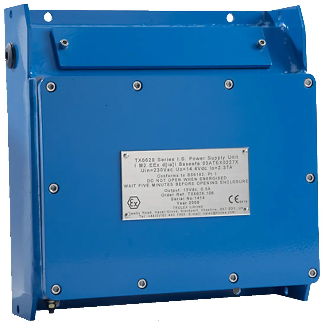
Product Overview
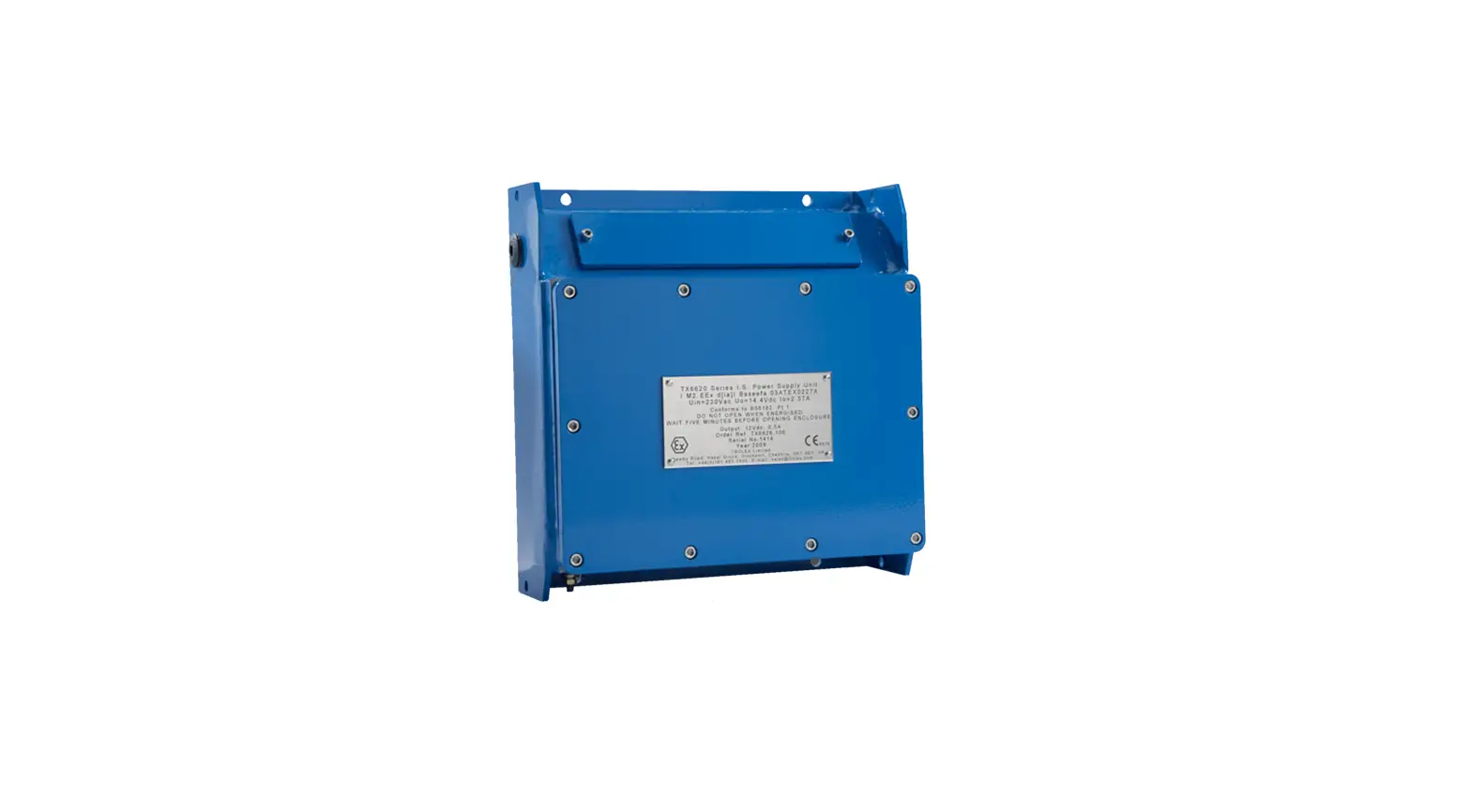
The TX6649 Power Supply converts an ac supply voltage into a stabilised and regulated Intrinsically Safe source of power to approved sensors and electronic control devices.
Operation Feature
- Input voltage options: 110V ac or 230V ac
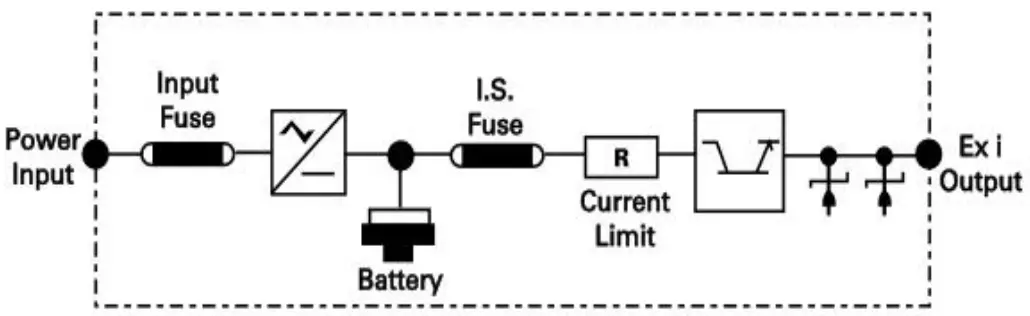
- Input supply is protected by two primary fuses
- Intrinsically Safe output voltage: 12V dc
- Output circuit is resistively limited in accordance with certification standards for Intrinsically Safe, ia, equipment
- Output circuit incorporates voltage regulation, current limiting and continuous short circuit protection
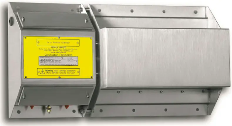
- Robust stainless steel housing
- Integral 3.5 Ah back-up battery with automatic uninterrupted power transfer and charge to full capacity
- Output relay contact to signal power failure
- Analogue output signal to indicate battery charge condition
- Battery conserve timer for use on mobile machinery
Application
- Mining
- Tunnelling
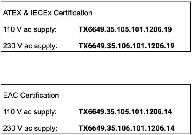
Product Options
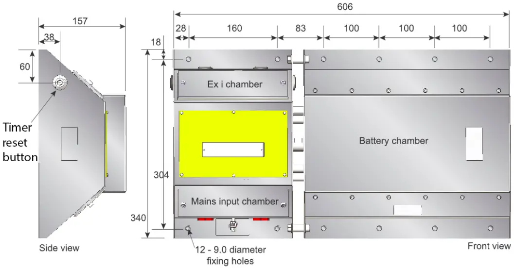
Dimensions
Technical Information
| 1 | Input voltage | 110 V ac ± 10% or 230 V ac ± 10% – 50/60 Hz |
| 2 | Output voltage | 12 V dc |
| Output current | 750 mA | |
| Output ripple/noise | 150 mV max | |
| Line regulation | <5% over the input voltage range | |
| Load regulation | <5% over 0 to 90% of load current <10% between 90% and 100% of load current | |
| Voltage limiting | Over voltage detection with crowbar protection and short circuit protection | |
| Current limiting | Automatic current limiting of the intrinsically safe output also limits the current to less than the rupturing capacity of the output protection fuse. |
| 3 | Max. operating temperature | –20°C to +40°C |
| Storage temperature | –20°C to +70°C | |
| Humidity | 0 to 95% RH, non-condensing | |
| Vibration limits / low frequency | 0.25 mm peak, sinusoidal vibration in the range 10 Hz to 100 Hz in 3 perpendicular planes | |
| Medium frequency | 2g peak, sinusoidal vibration in the range 10 Hz to 600 Hz in 3 perpendicular planes | |
| Mechanical shock | 1000 shocks of 40g minimum in 3 perpendicular planes | |
| Housing material | Stainless steel |
| 4 | Back-up battery | Sealed lead-acid. 25 Ah Automatic charge control to full capacity Automatic uninterrupted output power transfer following input power failure |
| Power fail indication | Relay contacts change state on power failure. Contact rating: 0.25 A at 30 V dc max. | |
| Charge condition | Analogue output signal proportional to the charge level of the battery Choice of 0.4 V to 2.0 V or 4 to 20 mA signals | |
| Battery life | 6 years at 20°C 3 years at 30°C 1.5 years at 40°C | |
| Net weight | 35 kg | |
| Important note | Following initial commissioning or long periods of storage the TX6648 requires a minimum of 24 hours charge time before the batteries will be at full capacity. |
Certification & Conformity
 | ATEX (European Union) certification for use in underground mines (Group I). Complies with ATEX Directive 2014/34/EU. |
| Standards: EN IEC 60079-0:2018 EN 60079-5:2015 EN IEC 60079-7:2015+A1:2018 EN 60079-11:2012 |
 | IECEx (International) certification for use in underground mines (Group I). |
| Standards: IEC 60079-0:2017 IEC 60079-5:2015 IEC 60079-7:2015+AMD1:2017 IEC 60079-11:2011 |
 | EAC certification for use in underground mines in Eurasian Customs Union (including Russia). |
Underground mines
| Product Code: | Ex Certificate Number: | Ex Certification Code: |
| TX6649.35(.xx…).19 25 Ah UPS Power Supply | CML 21ATEX2404X IECEx CML 21.0048X | I M2(M1) Ex eb q [ia Ma] I Mb (see Note 1) I M1 Ex ia I Ma (see Note 2) Ta = -20 ˚C to +55 ˚C |
| TX6649.35(.xx…).14 25 Ah UPS Power Supply | RU C-GB.AA87.B.00155/19 | PП Ex e q [ia Ma] I Mc X (see Note 1) PO Ex ia I Ma X (see Note 2) Ta = -20 ˚C to +40 ˚C |
Note 1 —applies when mains powered
Note 2 —applies when powered from the backup battery
The following Specific Conditions of Use apply to the ATEX and IECEx certificates listed above:
The following conditions relate to safe installation and/or use of the equipment:
i. All cable entries shall be made using suitably certified Ex e cable glands
ii. The use of conduit is not permitted.
Installing
Safety Precautions
The installation of the product must only be carried out by competent personnel.
Each installation needs to be considered with reference to the local safety regulations and authorities. Refer to the following standards for additional guidance:
- IEC/EN 60079-14
- IEC/EN 60079-25
- Make sure that all covers on Ex e housings and their fixing devices are properly secured in compliance with statutory regulations before switching on the input supply.
- Never remove the cover of an Ex e housing whilst the input supply is connected. Isolate elsewhere before removing the cover in accordance with statutory regulations.
- The housing of all power supplies must be securely earthed in compliance with statutory regulations.
- Carry out a current consumption audit to ensure that the maximum current loading of the power supply is not exceeded.
- Ensure that the installation of the power supply, particularly with regard to the connecting cables, complies with the certification parameters (section 2.1).
- The Ex e housing must be inspected and maintained regularly in accordance with statutory regulations.
- All cables entering the mains input terminal chamber must be terminated with suitable, certified cable entry devices.
- Do not drill holes in the Ex e housing or modify it in any way.
- The battery contains corrosive substances and must be disposed of in the correct way.
- Please return the complete unit to Trolex or an approved distributor for servicing and replacement.
Handling
The TX6649 weighs 35 kg and safe handling and transportation should be applied in line with the heath and safety reccommendations on your site
Tools and Test Equipment Required
No special tools are needed.
Siting Recommendations
- The TX6649 may be located in hazardous areas of mines susceptible to firedamp and coal dust (Group )
- The equipment should not be used outside of its certified ambient temperature range.
- Installation shall be carried out in accordance with the applicable code of practice by suitably trained personnel.
Positioning Recommendations
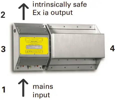
Mount horizontally as shown in the illustrations on pages 4 and 7.
Commissioning / verification tests prior to first use.
Prior to commissioning and first use, the product should be inspected for any visible damages and integrity of the enclosure. Never use the product that has damaged housing in hazardous locations.
Power Requirements
See Technical Information section 1.5.
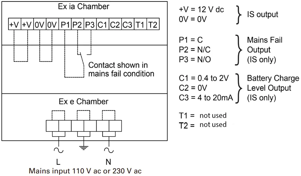
Output Signal
0.4to2Vdc Battery charge level monitor
4 t0 20 mA Battery charge level monitor
Relay Mains fail output contact
Connections
Group | Areas
Connecting cables must conform to the requirements of the appropriate Approval and Certification standards for Mining applications. Trolex recommends that they conform to BS5308.
Maintenance
The maintenance of the product must only be carried out by competent personnel.
Maintenance shall be considered with reference to the local safety regulations and authorities. Refer to the following standards for additional guidance:
- IEC/EN 60079-17
Make periodic visual inspections to check for physical damage.
Check connections in both terminal chambers are secure.
The product is marked with the following warning, which is applicable to the power supply enclosure only:
THIS CONTAINER HAS BEEN PERMANENTLY SEALED AND CANNOT BE REPAIRED
Technical Maintenance
Trolex recommends that the batteries are replaced every three years. This must be carried out by a competent person. If the unit is returned to Trolex for this re-work, a test of the internal safety integrity will also be carried out.
Warranty
See Terms and Conditions for the Supply of Goods and/or Services at
www.trolex.com.
Diagnostics
| Condition: | Output reading of 800mV instead of 12Vdc. |
| Diagnosis: | The internal safety crowbars have activated due to an external condition on the input voltage or output side, the crowbars will attempt to automatically reset. If this does not happen remove main power for about 2 minutes. |
| Condition: | The output has dropped to zero |
| Diagnosis: | It is probable that the input fuses have ruptured which has resulted in the batteries completely discharging. To check this, remove main power momentarily. If the relay does not change state then it confirms the unit is continuously operating on the battery supply only. |
Connectivity
Check the correct function of the mains-fail relay by connecting a suitable test meter across the contacts.
A 12V dc output should be available at the intrinsically safe output terminals with mains power input present, or absent.
Also check that the analogue battery monitoring signal is available at the output terminals.
Support
If you need technical support to operate this product, or would like details of our after sales technical support packages, contact [email protected].
Disclaimers
The information provided in this document contains general descriptions and technical characteristics of the performance of the product. It is not intended as a substitute for and is not to be used for determining suitability or reliability of this product for specific user applications. It is the duty of any user or installer to perform the appropriate and complete risk analysis, evaluation and testing of the products with respect to the relevant specific application or use. Trolex shall not be responsible or liable for misuse of the information contained herein. If you have any suggestions for improvements or amendments, or find errors in this publication, please notify us at [email protected].
No part of this document may be reproduced in any form or by any means, electronic or mechanical, including photocopying, without express written permission of Trolex.
All pertinent state, regional, and local safety regulations must be observed when installing and using this product. For reasons of safety and to help ensure compliance with documented system data, only Trolex or its affiliates should perform repairs to components.
When devices are used for applications with technical safety requirements, the relevant instructions must be followed.
Trademarks
© 2013 Trolex® Limited.
Trolex is a registered trademark of Trolex Limited. The use of all trademarks in this document is acknowledged.
Document History
Issue 1 20 July 2005 Original publication of this document
Issue 2 6 September 2013 New format and minor revisions
Rev A 14 March 2022 General revisions
Trolex Ltd, Newby Road, Hazel Grove, Stockport, Cheshire, SK7 5DY,
UK+44 (0) 161 483 1435 [email protected]
At Trolex, we save lives.
We believe that no person should risk their life to earn a living.
Our aim is to become the world’s leading name in health and safety technology, through pioneering products that provide real-world benefits to our customers, whenever workers operate in hazardous environments.
For more information about Trolex, please contact us at:
Enquiries
[email protected]
Telephone
+44 (0) 161 483 1435
Fax
+44 (0) 161 483 5556
Trolex Ltd
Newby Road, Hazel Grove
Stockport, Cheshire
SK7 5DY, United Kingdom
Website
www.trolex.com
 /company/trolexUK
 trolexUK
 /trolexUK
 /user/TrolexUK


