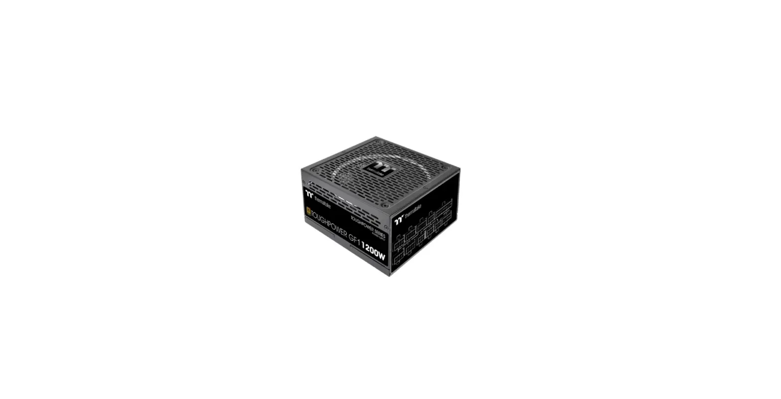
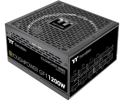
thermaltake PS-TPD-1200FNFAGE-4 Toughpower GF1 1200W Desktop Power Supply
Warnings and Caution
- Do not unplug the AC power cord when the power supply is in use. Doing so may cause damage to your components.
- Do not place the power supply in high humidity and /or temperature environment.
- High voltages exist in the power supply. Do not open the power supply case unless you are an authorized service technician or electrician. Doing so will void the warranty.
- The power supply should be powered by the source indicated on the rating label.
- Make sure all cables are plugged in properly. Loos and improper connections would damage the power supply and your system.
- Please use only genuine Thermaltake modular cables with Thermaltake power supply models. Third-party cables might not be compatible and could cause serious damage to your system and power supply. The warranty is voided with the use of third-party cables.
- All warranties and guarantees will be voided, if failure to comply with any of the warnings and cautions covered in this label.
Components Check
- TOUGHPOWER GF3 power supply unit
- AC power cord
- User manual
- Mounting screws x 4
- Cable straps x 4
Power Connector Introduction
| CABLE
Wattage | 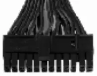 | 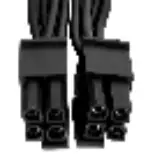 |  | 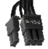 |  |  |  |
| Main Power Connector (24 Pin) | ATX Connector (8 Pin/4+4 Pin) | SATA Connector (5 Pin) | PCIe Connector (6+2 Pin) | PCIe Connector (12+4 Pin) | Peripheral Connector (4 Pin) | Floppy Adapter (4 Pin) | |
| 1200W | 1 | 2 | 12 | 4 | 1 | 4 | 1 |
| 1000W | 1 | 2 | 12 | 4 | 1 | 4 | 1 |
| 850W | 1 | 2 | 12 | 4 | 1 | 4 | 1 |
| 750W | 1 | 2 | 12 | 4 | 1 | 4 | 1 |
Output Specification
| Continuous Power | AC INPUT | Input Voltage: 100V – 240V~ ; Input Current: 15.0A / 7.0A ; Frequency: 50Hz / 60Hz | ||||
| 1200W | DC OUTPUT | +3.3V | +5V | +12V | -12V | +5VSB |
| Max Output Current | 22A | 22A | 100A | 0.3A | 3.0A | |
| Max Output Power | 120W | 1200W | 3.6W | 15W | ||
| Continuous Power | AC INPUT | Input Voltage: 100V – 240V~ ; Input Current: 13.0A / 6.5A ; Frequency: 50Hz / 60Hz | ||||
| 1000W | DC OUTPUT | +3.3V | +5V | +12V | -12V | +5VSB |
| Max Output Current | 22A | 22A | 83.5A | 0.3A | 3.0A | |
| Max Output Power | 120W | 999.6W | 3.6W | 15W | ||
| Continuous Power | AC INPUT | Input Voltage: 100V – 240V~ ; Input Current: 10.0A / 5.0A ; Frequency: 50Hz / 60Hz | ||||
| 850W | DC OUTPUT | +3.3V | +5V | +12V | -12V | +5VSB |
| Max Output Current | 22A | 22A | 70.8A | 0.3A | 3.0A | |
| Max Output Power | 120W | 849.6W | 3.6W | 15W | ||
| Continuous Power | AC INPUT | Input Voltage: 100V – 240V~ ; Input Current: 10.0A / 5.0A ; Frequency: 50Hz / 60Hz | ||||
| 750W | DC OUTPUT | +3.3V | +5V | +12V | -12V | +5VSB |
| Max Output Current | 22A | 22A | 62.5A | 0.3A | 3.0A | |
| Max Output Power | 120W | 750W | 3.6W | 15W | ||
Installation Steps
Note: Make sure that your system is turned off and unplugged. Disconnect the AC power cord from your old power supply.
Step 1
Removing Your existing power supply
- Make sure that your system is turned off and unplugged.
- Disconnect the AC power cord from your wall outlet or UPS and the existing power supply.
- Disconnect all the power cables from your graphic card, motherboard, and all other peripherals.
- Follow the directions in your chassis manual and uninstall your existing PSU.
Step 2
- Make sure the power supply’s AC power cable is not connected.
- Follow the directions in your chassis manual and install the power supply with the screws provided.
- Connect the 24-pin or 20-pin main power cable to the motherboard.
- Connect the eight-pin +12V (EPS12V) cable to the motherboard.
- If your motherboard has an eight-pin +12V socket, connect the eight-pin cable directly to your motherboard.
- If your motherboard has a four-pin socket, detach the four-pin from the eight-pin cable, and then plug this
four-pin cable directly to your motherboard.
- Connect the peripheral cables, PCI-Express cables, and SATA cables.
- Connect the SATA power connector to devices with a Serial ATA interface.
- Connect the 6+2pin or 12+4pin PCI-E power connector to the PCI-E graphic cards if required.
- Connect the 4-pin peripheral power connector to peripherals devices if needed.
- Connect the AC power cord to the power supply and turn it on by pushing the switch to the ON position (marked with “I”).
Attention!
When the Smart Zero Fan mode is turned on, the fan will not spin until the load exceeds 30% of the power supply, minimizing the fan noise; It is normal if the fan does not operate when the computer is at a low working load.
Total Protection
- Over Voltage Protection
Voltage Source +3.3V 3.76V~4.5V +5V 5.74V~7.0V +12V 13.4V~15.6V - Under Voltage Protection
Voltage Source +3.3V 2.83V max. +5V 4.47V max. +12V 9.8V max. - Over Current Protection
Voltage Source Protection Point +3.3V 180% max. +5V 180% max. +12V 150% max. - Short Circuit Protection
Activated when any DC rails short-circuited. - Over Power Protection
The power supply shall be shut down and latch off, if the wattage of the power supply is 110% 150% over continuous power. - Over Temperature Protection
Protection temperature is 50℃ to 70℃ at 115V and full load.
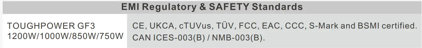
EMI & SAFETY
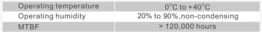
Environments
Trouble-Shooting
If the power supply fails to function properly, please follow the troubleshooting guide before applying for service:
- Is the power cord plugged properly into an electrical outlet and into the power supply AC inlet?
- Please make sure the I/O switch on the power supply is switched to I position.
- Please make sure all power connectors are properly connected to all the devices.
- If connected to a UPS unit, is the UPS on and plugged in?
If the power supply is still unable to function properly after following the above instruction, please contact your local store or Tt branch office for after-sales service. You may also refer to Thermaltake’s website for more technical support: thermaltake.com


