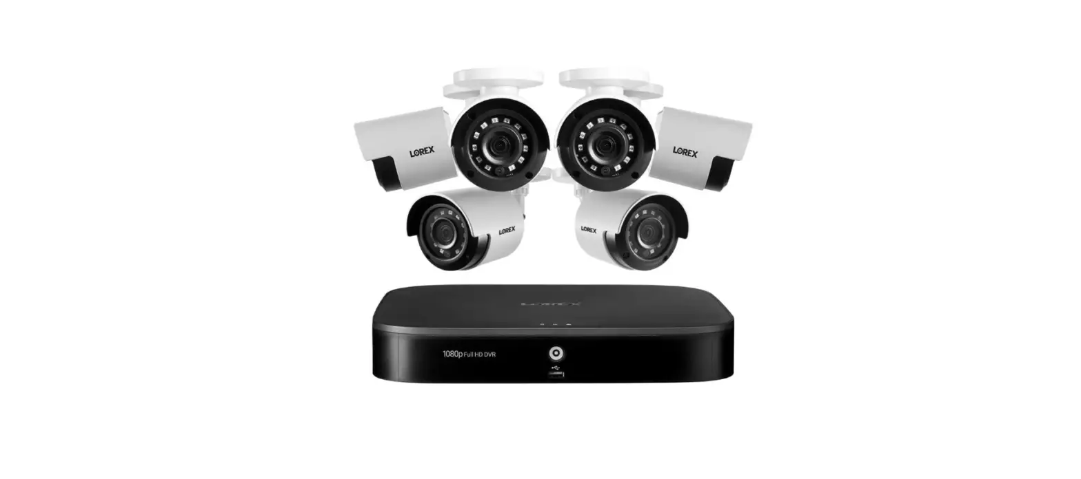
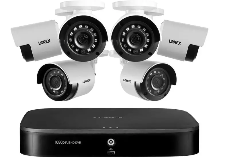
Lorex D241A81-62NA Indoor-Outdoor Wired Security Camera System
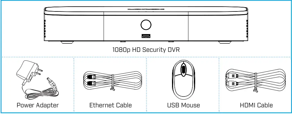
Package Contents
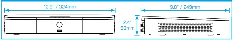
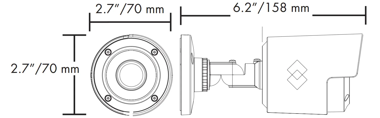
Dimensions
Setting Up Your Recorder
See the steps below (expanded instructions to the right) to complete initial setup of the recorder: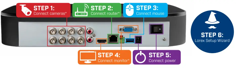
Overview of extra ports: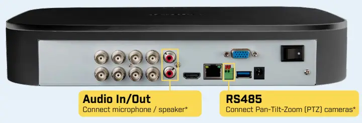
NOTE: For full instructions on using the extra ports, please refer to your security recorder’s instruction manual at lorex.com.
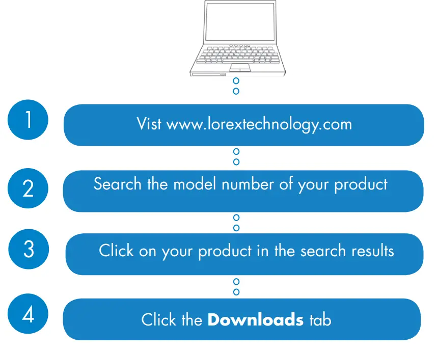
Need Help?
Visit us online for up-to-date software and complete instruction manuals.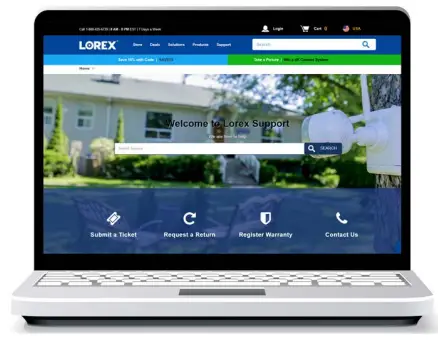
- Visit lorex.com
- Search for the model number of your product
- Click on your product in the search results
- Click on the Downloads tab
Back panels shown below are for illustration only. Your recorder’s back panel may appear different, with all the same ports in different locations.
STEP 1: Connect cameras*
Test your cameras prior to selecting a permanent mounting location by temporarily connecting the cameras and cables to your DVR. 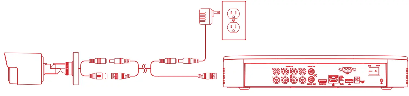
NOTES
- The extension cable must be a single stretch of cable between the recorder and the camera. You cannot connect multiple extension cables to each other.
- This guide covers connecting cameras to your security recorder only. For full instructions on installing your cameras, please refer to your camera’s documentation at lorex.com.
- Before selecting a permanent mounting location for your cameras, see Ensuring Accurate Person and Vehicle Detection below for important camera installation notes.
STEP 2: Connect router*
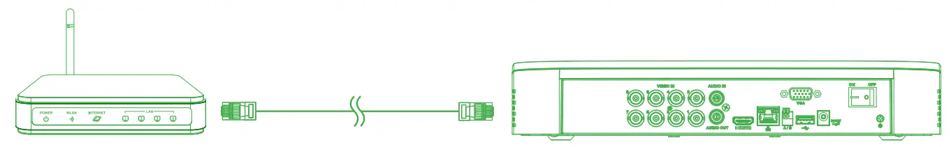
Connect the recorder to your router using the included Ethernet cable.
NOTE: To receive automatic firmware updates and enable remote viewing with mobile apps, a high-speed Internet connection is required (minimum upload speed of 3.5Mbps required for remote viewing). All other system features can be used without an Internet connection.
STEP 3: Connect the mouse
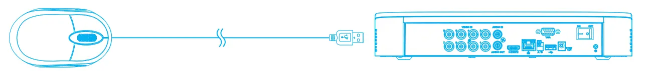
Connect the included mouse to a USB port on the recorder.
STEP 4: Connect monitor*
Connect the recorder to a monitor using the included HDMI cable or a VGA cable (not included).
Both HDMI and VGA ports support up to 1080p output resolution.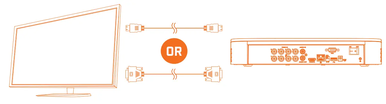
IMPORTANT: The system will automatically match the resolution of the connected monitor the first time you use the recorder. If you need to switch monitors, make sure you set the recorder to an output resolution supported by the new monitor before switching. See Changing the Recorder’s Output Resolution on the rear for details.
STEP 5: Connect power
Use the included power adapter to connect the recorder to a nearby outlet. Turn the recorder on using the power switch on the back panel.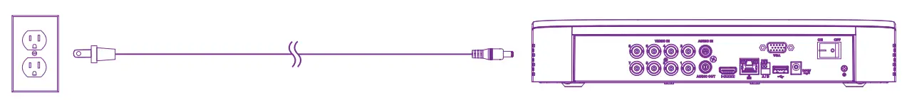
STEP 6: Lorex Setup Wizard
When you first power up your recorder, the Lorex Setup Wizard will begin. The Wizard will help you configure core system settings.
You will also create a secure password. For future reference, it is recommended that you record your password here: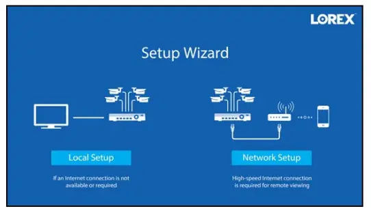
Record your password below and store in a secure place.
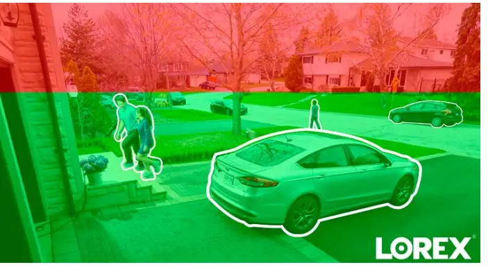
Ensuring Accurate Person and Vehicle Detection
The following are important camera installation notes to ensure accurate person and vehicle detection. For full camera mounting instructions, see your camera’s documentation at lorex.com.
- Angle the camera so that objects of interest appear in the bottom ⅔ of the camera image.
- Choose a location where objects of interest will be no further than 50ft (~15m) from the camera.

Lower accuracy for objects further away than 50ft (~15m) and/or in the top ⅓ of the image.
Optimal accuracy for objects within 50ft (~15m) and in the bottom ⅔ of the image. - Angle the camera between 30~60° down from the level position.
- Install the camera between 8-16ft (2.5-5m) off of the ground.
NOTE: Accuracy of person and vehicle detection will be influenced by multiple factors, such as the object’s distance from the camera, the size of the object, and the height and angle of the camera. Night vision will also impact the accuracy of detection.
Additional Installation Tips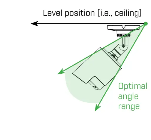
- Point the camera where there is the least amount of obstructions (e.g., tree branches).
- Install the camera that vandals cannot easily reach.
- Secure cabling so that it is not exposed or easily cut.
- This camera is rated for outdoor use. Installation in a sheltered location is recommended.
Once you have completed all steps for initial setup on the front of this guide, please refer to the following sections to learn more about using your system.
Using the Mouse
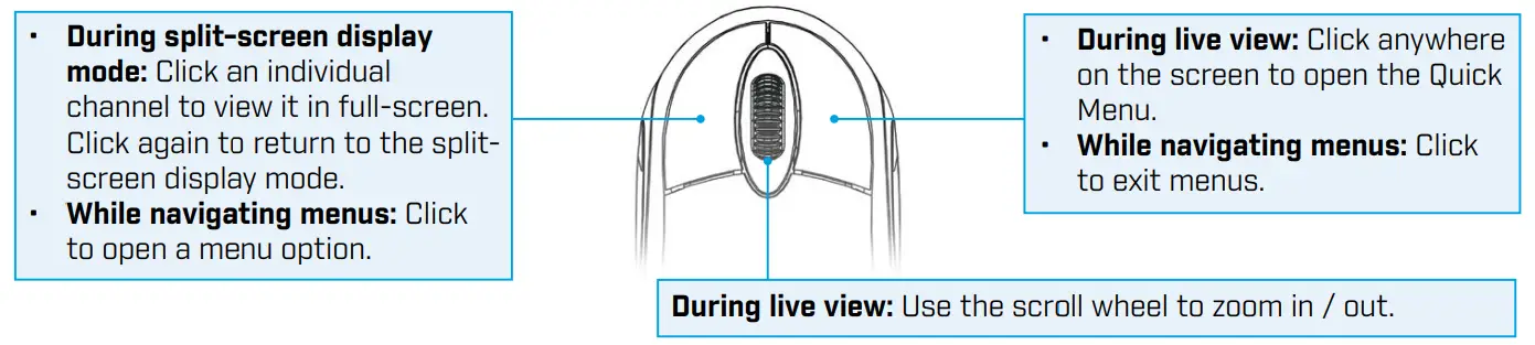
NOTE: In live view, hover the mouse cursor over the top of the screen to open the Navigation Bar. Move the mouse cursor away from the top of the screen to close the Navigation Bar.
Quick Access to System Information
To quickly open a window that displays vital system information such as device ID, model number, firmware version, and IP address:
Using the Mouse
Quick Access to System Information
- Tap the button on the front panel of the recorder.
- Right-click to open the Quick Menu and click Info.
Right-click anywhere on the live viewing screen to open the Quick Menu.
- Open Main Menu.
- Search and playback recordings.
- Control PTZ cameras (not included).
- Select camera / live display view.
- View previous/next channel(s).
- View system information.
- Start/stop sequence mode.
- Temporarily disable all current audible warnings.
- Open manual recording controls.
- Adjust camera color and image settings.
Changing the Recorder’s Output Resolution
The system will automatically match the resolution of the connected monitor the first time you use the recorder.
IMPORTANT: If you need to switch the monitor, make sure you set the recorder to an output resolution supported by the new monitor before switching.
To change the recorder’s output resolution:
- From the live view, right-click and then click Main Menu. If prompted, log in using the system user name (default: admin) and your new, secure password.
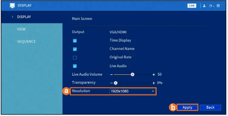
- Click DISPLAY, then configure the following:
- Set Resolution to match the highest resolution supported by your monitor. For example, select 1920×1080 for 1080p monitors, or 1280×720 for 720p.
- Click Apply. The recorder will restart before changes take effect.

Playback
Search through and play video recordings from the hard drive.
To search for and play recordings:
- From live view, right-click and then click Playback. If prompted, log in using the system user name (default: admin) and your new, secure password.
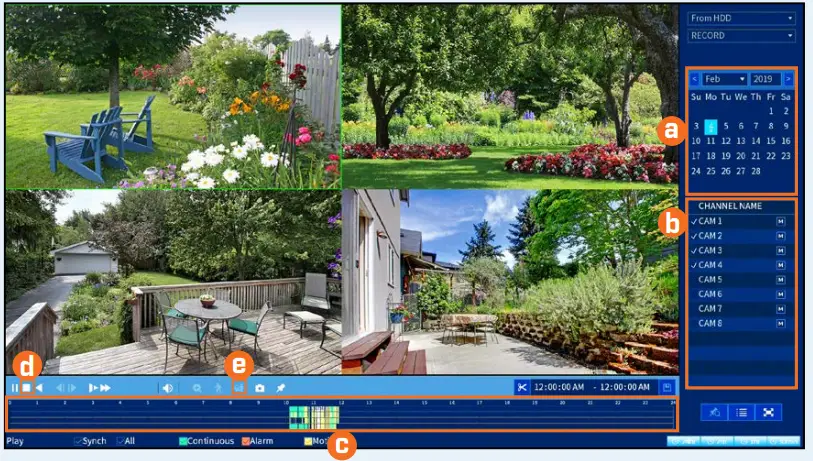
- Configure the following

- Use the calendar on the right to select the date to playback. heck channels you want to play back.
- Click the icon beside each selected channel to select Mainstream (M) or Substream (S) video quality.
- Click inside the video bar to select the playback time. Playback starts immediately at the selected time.
To filter for person/vehicle recordings: - PREREQUISITE: You must enable Smart Motion Detection on any and all channels you would like to filter for person/vehicle detection. See the section Motion & Advanced Person/Vehicle Detection for details.
- Click
 to stop current playback.
 - Hover over the
 icon. Check Person / Vehicle to filter available playback events.
Wait a few seconds for the video bar to show detection events.
Backup
Back up recordings from the hard drive to a USB flash drive (not included).
To back up recordings
- Insert a formatted USB flash drive (not included) into a free USB port on the recorder.
- From live view, right-click and then click Main Menu. If prompted, log in using the system user name (default: admin) and your new, secure password.
- Click BACKUP.
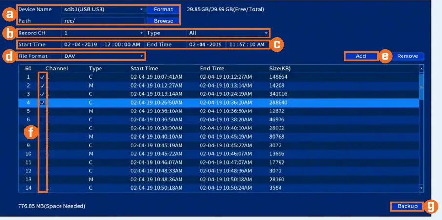
- Configure the following:
- Select your USB drive and the folder for the backup.
- Select the channel(s) and recording types to search by.
- Select a start and end time.
- Choose a file format.
- Click Add to see recordings that match your search.
- Check the boxes next to the recordings you want to back up.
- Click Backup.

Motion & Advanced Person/Vehicle Detection
Set preferences for motion detection. This section includes setup of person/vehicle detection. By default, person/vehicle detection is enabled on channels 1 and 2.
To configure motion & advanced person/vehicle detection:
- From live view, right-click and then click Main Menu. If prompted, log in using the system user name (default: admin) and your new, secure password.
- Click ALARM. Click MOTION on the far-left, then click the Motion Detect tab.
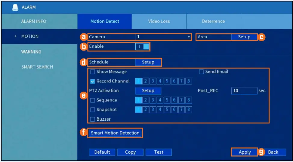
- Configure the following:

- Select the channel you would like to configure.
- Click Enable.
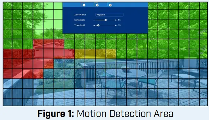
- Click Setup next to Area to set an active area for motion detection. See Figure 1 below for details.
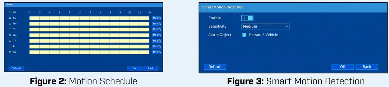
- Click Setup next to Schedule to set the weekly schedule for motion detection. See Figure 2 below for details.
- Set preferences for how the system reacts to motion detection events.
- Click Smart Motion Detection to enable person/vehicle detection.
See Figure 3 below for details. - Click Apply to save changes.
- The camera image appears with a red grid overlay.
This means the entire image is enabled for motion detection. - Click or click and drag to add/remove boxes from the active area. Cells that have been removed from the active area appear green.
- Hover near the top of the image to reveal zone selection. You can set up 3 different zones with different sensitivity and threshold values.
- Right-click when finished.

- The default schedule, shown in Figure 2, is active at all times.
- Click Modify to change the schedule for the corresponding day of the week.
- Click OK when finished.

- Click Enable to allow the detection of people and vehicles on the selected channel.
IMPORTANT: A maximum of 2 channels will support person/vehicle detection at once. By default, channels 1 and 2 have person/vehicle detection enabled. - Select a Sensitivity level (a high sensitivity value will detect smaller objects than a low value).
- Check Person / Vehicle.
- Click OK when finished.
Configuring Deterrence Settings
Set preferences for automatic warning light triggering on compatible Lorex deterrence cameras.
For a complete list of compatible deterrence cameras, navigate to your recorder series at lorex.com/compatibility.
To configure deterrence settings:
- In live view, right-click and click Main Menu. If prompted, log in using the system user name (default: admin) and your new, secure password.
- Click ALARM. Click MOTION on the far-left, then click the Deterrence tab.
- Configure the following:

- Select the channel of a connected deterrence camera.
- Check Enable.
- Click Setup next to Warning Light to configure preferences.
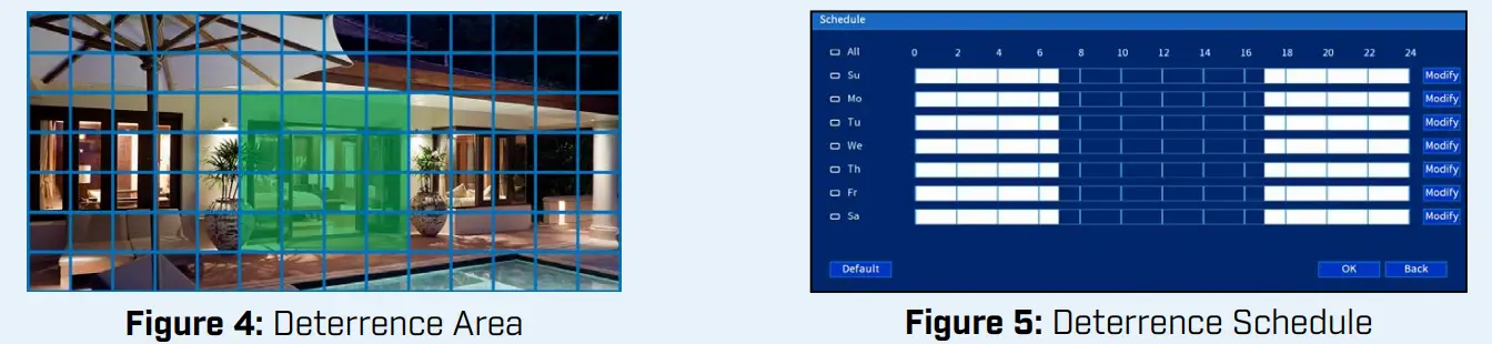
- Click Setup next to Area to set an active area for automatic deterrence. See Figure 4 below for details.
- Click Setup next to Schedule to set the weekly schedule for automatic deterrence. See Figure 5 below for details.
- Click Apply.
- The camera image appears with a grid overlay. The green area is the active area for deterrence.
- Click or click-and-drag to add/remove boxes from the active area.
- In Figure 4, only move around the doorway will trigger warning light.
- Right-click when finished.

- The default schedule, shown in Figure 5, is active during the night, between 5 pm and 7 am.
- Click Modify to change the schedule for the corresponding day of the week.
- Click OK when finished.
- To set off all connected deterrence cameras’ warning lights and sirens, press and hold the front panel button for 3 seconds.

Contents
- IR Night Vision Camera*
- Mounting Kit*
- 60ft BNC / Power Extension Cable*
- Power Adapter**
* Per camera in multi-camera packs.
**A Multi-Camera Power Adapter that provides power to multiple cameras or individual power adapters may be provided, depending on product configuration.
ATTENTION – It is recommended to connect the camera to the DVR or an external PoE switch. If using a DC power adapter with the camera, a REGULATED UL / CSA APPROVED power supply is REQUIRED for use with this camera. Use of a non-regulated, non-conforming power supply can damage this product and voids the warranty.
Warning/Caution
- Read this guide carefully and keep it for future reference.
- Follow all instructions for safe use of the product and handle with care.
- Use the cameras within given temperature, humidity and voltage levels noted in ‘Camera Specifications’.
- Do not disassemble the cameras.
- Do not point the cameras directly toward the sun or a source of intense light.
- Use only the supplied regulated power supply. Use of a non-regulated, non-conforming power supply can damage this product and voids the warranty.
- periodic cleaning may be required. Use a damp cloth only. Do not use harsh cleaners or aerosol cleaners.
Installation Tips
- Point the cameras where there is the least amount of obstructions (i.e. tree branches).
- Install the cameras where they are difficult for vandals to reach.
- Secure cabling so that it is not exposed or easily cut.
- Cameras rated for outdoor use. Installation in a sheltered location is recommended.
Dimensions
Disclaimers:
* Compatible with Lorex MPX series DVRs only.
** Stated IR illumination range is based on ideal conditions in typical outdoor night time ambient lighting and in total darkness. Actual range and image clarity depend on the installation location, viewing area, and light reflection/absorption level of object.
*** Not intended for submersion in water. Installation in a sheltered location is recommended.
Resources
Installing the Cameras
ATTENTION – Test each camera prior to selecting a permanent mounting location by temporarily connecting the camera(s) and cables to the DVR.
Before installing the cameras: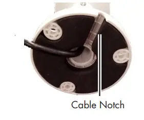
- Decide whether to run the cables through the wall/ceiling (drilling required) or along the wall/ceiling.
- If you run the cables along the wall/ceiling, you must run the cable through the cable notch on the base.
This will keep the camera base flush to the surface when mounted.
To install the cameras:
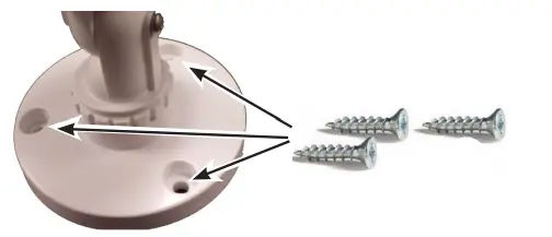
- Set the camera in the desired mounting position and mark holes for screws through the camera base.
- Drill the holes, then feed the cable through the mounting surface or cable notch.
NOTE: Insert the included drywall anchors if installing the camera in drywall. - Mount the camera stand to the surface using the provided screws. Make sure all screws are fastened tightly.

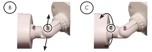
Adjusting the Camera 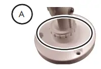
- Rotating the arm:
Loosen the adjustment ring between the camera arm and base by turning the ring counter-clockwise. Rotate the arm of the camera (up to 360°). When the arm is in the position you want, tighten the adjustment ring against the base by turning the ring clockwise. - Bending the arm:
Use a Phillips head screwdriver (not included) to loosen the adjustment screw. Bend the arm of the camera to the position you want (up to 90°). Tighten the screw.
- Rotating the camera:
Use the screwdriver to loosen the adjustment screw. Rotate the camera to the position you want (up to 360°). Tighten the screw.
Connecting the Cameras
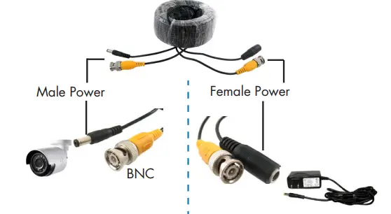
- Connect the BNC and power connectors to the camera.
- Connect the BNC connector to the video input of your DVR.
- Connect the power connectors to the power adapter.
Power Adapter Types
A multi-camera power adapter that provides power to multiple cameras or individual power adapters may be provided, depending on product configuration.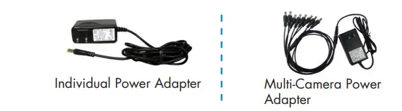
Setup Diagram
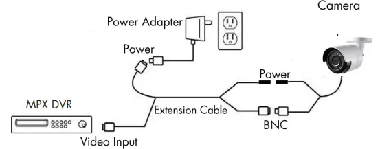
ATTENTION
This camera includes an Auto Mechanical IR Cut Filter. When the camera changes between Day/Night viewing modes, an audible clicking noise may be heard from the camera. This clicking is normal and indicates that the camera filter is working.
Cable Extension Options
Extend the cable run for your camera depending on the cable type used. Additional extension cables sold separately. See the table below:
Option | Cable Type | Max Cable Run Distance |
1 | Lorex model MCBL-60BNCU / MCBL- 60BNCU2 BNC Cable (included with camera) | 60ft / 18m |
2 | ‘RG59’ or ‘Coax’ or ‘Coaxial BNC’ Siamese (Video and Power) | 300ft / 92m |
3 | ‘RG59’ or ‘Coax’ or ‘Coaxial BNC’ (Video Only)2 | 800ft / 242m |
Notes:
- The extension cable must be a single stretch of cable between the DVR and camera. You cannot connect multiple extension cables to each other.
- For cable runs above 300ft / 92m (option 3), you must connect the power adapter directly to the camera, rather than at the end of the extension cable.
- Indicators that your cable run may be too long:
- Video is permanently black & white (even during day time)
- Video is unclear, soft, or distorted
- For more information on extension cables, visit www.lorextechnology.com.
Troubleshooting
Problem | Solution |
No picture / signal | • 1080p cameras are compatible with 1080p HD DVR recorders. 720p cameras are compatible with 720p & 1080p HD DVR recorders. • Ensure connections are properly connected. • Ensure the camera power supply is plugged in. |
Picture is too bright | • Ensure your camera isn’t pointed directly at a source of light (e.g. sun or spot light). • Move your camera to a different location. |
Picture is too dark | • Check the brightness and contrast settings of the DVR or monitor. |
Night vision is not working | • The night vision activates when light levels drop. The area may have too much light. |
Picture is not clear | • Check the camera lens for dirt, dust, spiderwebs. Clean the lens with a soft, clean cloth. • Make sure that the cable run is within the limitations specified in the section ‘Cable Extension Options’. |
Bright spot in video when viewing camera at night | • Night vision reflects when pointing a camera at a window. Move the camera to a different location. |
FAQS
The included camera cables are 60ft/18m long.
Yes you can add users.
Yes.
No
No
Yes.
To how many wireless dives can I connect at the same time to watch the cameras
No.
Yes, please visit the manufacturer’s website to download the Lorex Cloud Mac or PC client.
Yes, except when it is dark outside and the cameras switch over to IR night vision mode which will cause the video feeds to show in greyscale.
We used an old computer monitor and it works great.
You will need a wireless mouse, purchase one separately, I had one already so it wasn’t an issue.
VIDEO


