 XAG RD2426 MIMO radar
PREVIEW
INTRODUCTION
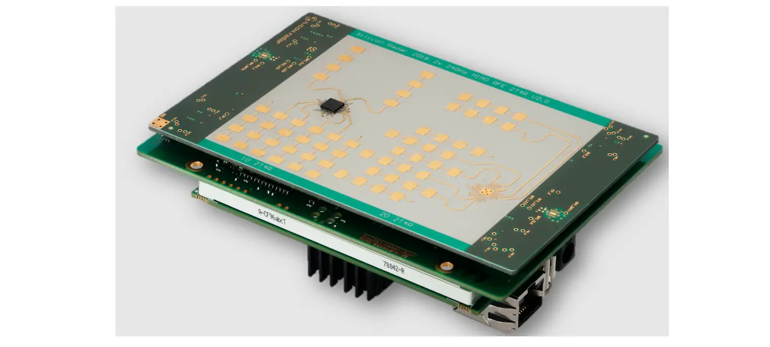
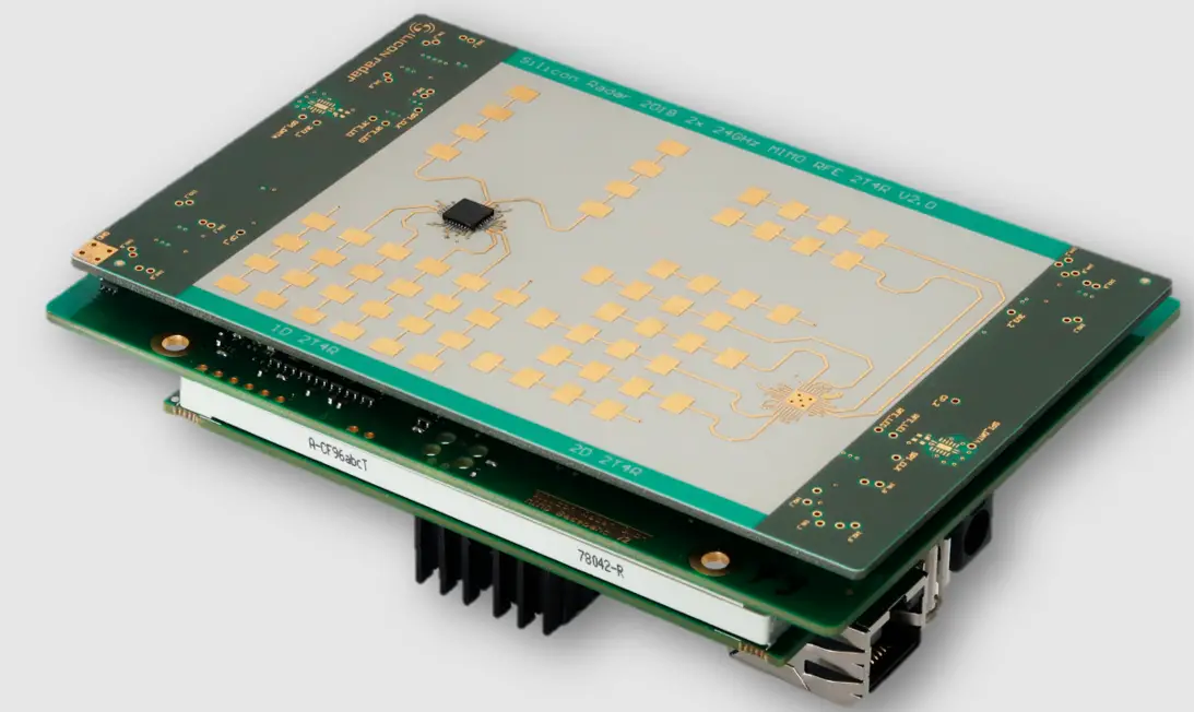
RD2426 is a MIMO radar that can swing. It is used in the UAV platform to detect the distance, speed and azimuth of obstacles and output point cloud images. The UAV uses the radar point cloud data to build a real-time 3D map, perceive the objects in the front of the UAV and independent avoidance of obstacles.
SPECIFICATIONS
| PARAMETER | TEST CONDITIONS | MIN | TYP | MAX | UNIT |
| System Features | |||||
| Frequency | 24.05 | – | 24.25 | Ghz | |
| Output Power(EIRP) | – | 17 | – | dBm | |
| Radiation Power | – | 50 | – | mW | |
| Modulation Mode | FMCW | ||||
| Swing Speed | – | 3 | – | Hz | |
| Measure Features | |||||
| Range | @FOV: azimuth±40°, elevation±45° | 1.5 | – | 25 | m |
| Range Accuracy | point target | ±0.1 | m | ||
| Speed | “-”means faraway from taget ,“+”means close to target | -13 | – | 13 | m/s |
| Speed Accuracy | Point taget | ±0.1 | m/s | ||
| Angle | Azimuth | -40 | – | +40 | ° |
| Elevation | -45 | – | 45 | ° | |
| Angle Accuracy | point target | ±1 | ° | ||
| Multiple Targets Resolution | |||||
| Range Resolution | point target,and 1.5~2 times of resolution can distinguish tow targets | 0.3 | m | ||
| Speed Resolution | 0.8 | m/s | |||
| Angle Resolution | Point target in FOV | 9.5 | ° | ||
| Antenna Features | |||||
| TX Antenna | – | 2 | – | NA | |
| RX Antenna | – | 6 | – | NA | |
| TX Antenna Gain | – | – | 17.4 | dB | |
| RX Antenna Gain | – | – | 15 | dB | |
| TX Bean Width | Azimuth@3dB | – | 10 | – | ° |
| Elevation@3dB | – | 45 | – | ° | |
| RX Bean Width | Azimuth@3dB | – | 10 | – | ° |
| Elevation@3dB | – | 72 | – | ° | |
| TX Sidelobe Level | – | – | -19.6 | dB | |
| RX Sidelobe Level | – | – | -20 | dB | |
| Interface Features | |||||
| CAN Interface | CAN-FD speed | – | 4 | – | Mbps |
| UART Interface | Baudrate | – | 115200 | – | Baud/s |
| Structure Features | |||||
| Size | Long*width*high | 94.4*88.9*138.5 | mm | ||
| Height | – | 174.3 | – | g | |
| Material | PBT+CF | ||||
OPERATING CONDITIONS
| PARAMETER | TEST CONDITIONS | MIN | TYP | MAX | UNIT |
| Operation Voltage | DC | 30 | 50 | 60 | V |
| Power Consumption | @50V | – | 6.5 | – | W |
| Working Temperature | -20 | +25 | +70 | ° | |
| Storage Temperature | -40 | 25 | +105 | ° | |
| Impact | 500m/s²@6 ms half-sine(10 x shock each in +/-X/Y/Z dir.) | ||||
| Vibration | 20m/s² peak at 10Hz/0.14m/s² peak at 1000Hz | ||||
| level of protection | IP67 | ||||
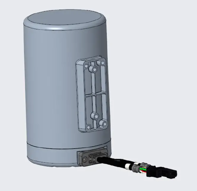
EXTERNAL INTERFACE
| WIRE GROUP | PIN | WIRE | PIN NAME | FUNTION |
| NUMBER | COLOR | |||
|
6 PINs Plug | 1 | Green | CAN_L | CAN Bus low level |
| 2 | Blue | CAN_H | CAN Bus high level | |
| 3 | Yellow | SYNC | Data Synchronization | |
| 4 | White | NC | No define | |
| 5 | Red | BAT+ | Positive Power Input | |
| 6 | Black | BAT- | Negative Power Input | |
|
4 PINs Plug | 1 | Green | UART_TX | UART TXD signal |
| 2 | Blue | UART_RX | UART RXD signal | |
| 3 | Red | PWR | 5V Power output | |
| 4 | Black | GND | 5V Power Ground |
LED INSTRUCTIONS
| NAME | COLOR | FUNCTION | GRAPHIC |
| PWR | Green | Power supply indicating,always on |
|
|
RUN |
Green | RF running,flash fast | |
| Updating the firmware with UART,flash
slowly | |||
| Updating the firmware with CAN,flash
fast | |||
| SYS | Green | System running well,flash in 1Hz |
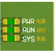
| frequency |
FCC Statement
This device complies with Part 15 of the FCC Rules. Operation is subject to the following two
conditions:
- This device may not cause harmful interference, and
- this device must accept any interference received, including interference that may cause undesired operation.This equipment has been tested and found to comply with the limits for a Class B digital device, pursuant to Part 15 of the FCC Rules. These limits are designed to provide reasonable protection against harmful interference in a residential installation. This equipment generates, uses and can radiate radio frequency energy and, if not installed and used in accordance with the instructions, may cause harmful interference to radio communications. However, there is no guarantee that interference will not occur in a particular installation. If this equipment does cause harmful interference to radio or television reception, which can be determined by turning the equipment off and on, the user is encouraged to try to correct the interference by one of the following measures:
- Reorient or relocate the receiving antenna.
- Increase the separation between the equipment and receiver.
- connect the equipment into an outlet on a circuit different from that to which the receiver is connected.
- Consult the dealer or an experienced radio/TV technician for help.
FCC Caution:
Any changes or modifications not expressly approved by the party responsible for compliance could void the user’s authority to operate this equipment. This transmitter must not be co-located or operating in conjunction with any other antenna or transmitter.This device meets all the other requirements specified in Part15C, Section 15.249 of the FCC Rules.
Radiation Exposure Statement:
This equipment complies with FCC radiation exposure limits set forth for an uncontrolled environment. This equipment should be installed and operated with minimum distance 20cm between the radiator & your body.
This device is intended only for OEM integrators under the following conditions:
- The antenna must be installed such that 20 cm is maintained between the antenna and users, and
- The transmitter module may not be co-located with any other transmitter or antenna.The OEM integrator is still responsible for testing their end-product for any additional compliance requirements required with this module installed.
IMPORTANT NOTE:
In the event that these conditions can not be met (for example certain laptop configurations or co-location with another transmitter), then the FCC authorization is no longer considered valid and the FCC ID can not be used on the final product. In these circumstances, the OEM integrator will be responsible for reevaluating the end product (including the transmitter) and obtaining a separate FCC authorization.The module is tested for standalone mobile RF exposure use condition. Any other usage conditions such as co-location with another transmitter (s) or being used in a portable condition will need a separate reassessment through a class II permissive change application or new certification.
End Product Labeling
This transmitter module is authorized only for use in device where the antenna may be installed such that 20 cm may be maintained between the antenna and users. The final end product must be labeled in a visible area with the following: “Contains FCC ID: 2A46G-RD2426”. The grantee’s FCC ID can be used only when all FCC compliance requirements are met.The end product shall bear the following 15.19 statement: This device complies with part 15 of the FCC Rules. Operation is subject to the following two conditions:- This device may not cause harmful interference, and
- This device must accept any interference received, including interference that may cause undesired operation.
OEM/Host manufacturer responsibilities
Must use the device only in host devices that meet the FCC/ISED RF exposure category of mobile, which means the device is installed and used at distances of at least 20cm from persons. OEM/Host manufacturers are ultimately responsible for the compliance of the Host and Module. The final product must be reassessed against all the essential requirements of the FCC rule such as FCC Part 15 Subpart B before it can be placed on the US market. This includes reassessing the transmitter module for compliance with the Radio and EMF essential requirements of the FCC rules. This module must not be incorporated into any other device or system without retesting for compliance as multi-radio and combined equipment.
Additional text needed for the host product manufacturer to provide to end-users in their end-product manuals. If RF exposure statements and use conditions are not provided, then the host product manufacturer is required to take responsibility of the module through a change in FCC ID (new application).


