![]() Type E Flexible 100 watt 12 Volt Solar Panel
Type E Flexible 100 watt 12 Volt Solar Panel
Instruction Manual Safety and Installation Instructions for
SunPower Type E, Type G and Type H AC Modules
United States and Canada
Contents are subject to change without notice.
Type E Flexible 100 watt 12 Volt Solar Panel
 https://www.sunpower.maxeon.com/int/PVInstallGuideULAC
For the latest version visit www.sunpower.maxeon.com/int/PVInstallGuideULAC
SunPower Corporation
www.sunpower.com
Safety and Installation Instructions for AC Modules
IMPORTANT SAFETY INSTRUCTIONS SAVE THESE INSTRUCTIONS
Introduction
This document provides safety and installation instructions for the UL Listed SunPower AC photovoltaic (PV) modules described herein, all of which bear the UL logo on the product label: ![]()
Important! Please read these instructions in their entirety before installing, wiring, or using this product in any way. Failure to comply with these instructions will invalidate the SunPower Limited Warranty for PV Modules.
1.1 Disclaimer of Liability
The installation techniques, handling and use of this product are beyond company control. Therefore, SunPower does not assume responsibility for loss, damage, or expense resulting from improper installation, handling, or use.
1.2 Nationally Recognized Testing Laboratory (NRTL) Listing Information
This product meets or exceeds the requirements set forth by UL 1703 or UL 61730, UL 1741 and UL 1741 SA for AC PV Modules. The UL 1703 Standard covers flat‐ plate PV modules intended for installation on buildings; or those intended to be freestanding. The UL 1741 SA Standard covers inverters, converters, controllers, and interconnection system equipment for use with distributed energy resources, including AC modules. The NRTL listing does not include integration into a building surface because additional requirements may apply. This product is not intended for use where artificially concentrated sunlight is applied to the module. The Type E and the Type G AC module models comply with HECO Rule 14H, CA CPUC Rule
21, 1547‐2003 and 1547a‐2014.
1.3 Limited Warranty
Module limited warranties are described in full in the SunPower warranty certificates obtainable at www.sunpower.com. In summary, the Limited Warranties do not apply to any of the following:
PV modules which in SunPower’s absolute judgment have been subjected to: misuse, abuse, neglect, or accident; alteration, improper installation, application, or removal. Including, but not limited to installation, application, or removal by any party other than a SunPower authorized Dealer; non‐observance of SunPower’s installation, user’s and/or maintenance instructions; repair or modifications by someone other than an approved service technician of SunPower; power failure surges, lightning, flood, fire, accidental breakage or other events outside SunPower’s control.
Safety Precautions
Before installing this device, read all safety instructions in this document.
Disconnect the utility AC source from all modules in the array before making or breaking electrical connections.
Danger! AC modules generate internal direct current (DC) and output alternating current (AC); and are a source of voltage when under load and when exposed to light. Electrical currents can arc across gaps and may cause injury or death if improper connection or disconnection is made; or if contact is made with module leads that are frayed or torn.
- Disconnect the utility AC source from all modules in the array before making or breaking electrical connections.
- Use only the AC locking connectors in order to defend against untrained personnel disconnecting the modules after they have been installed.
- All installations must be performed in compliance with the National Electrical Code (NEC) and any applicable local codes.
- Installation should be performed only by qualified personnel.
- Remove all metallic jewelry prior to installing this product to reduce the chance of accidental exposure to live circuits.
- Use only insulated tools to reduce your risk of electric shock.
- Do not stand on, drop, scratch, or allow objects to fall on modules.
- Broken glass, J‐boxes, broken connectors, and/or damaged backsets are electrical hazards as well as laceration hazards. If a module is cracked after installation, a qualified person should remove the module from the array and contact the supplier for disposal instructions.
- Do not install or handle modules when they are wet or during periods of high wind.
- Unconnected connectors must always be protected from pollution (e.g. dust, humidity, foreign particles, etc), prior to installation. Do not leave unconnected (unprotected) connectors exposed to the environment. A clean installation environment is essential in order to avoid performance degradation.
- Do not block drain holes or allow water to pool in or near module frames
- Contact your module supplier if maintenance is necessary.
- Save these instructions!
Electrical Characteristics
All electrical characteristics and grid interaction data are shown in Section 7. It is the installer’s responsibility to set the grid profile—this can only be done with internet access and the SunPower monitoring system.
If an installation involves a SunPower AC module which does not appear on this list please consult the product label on the back of the module or visit www.sunpower.com for the product datasheet.
3.1 Fire Rating
The AC module maintains the same Type 2 fire rating associated with DC modules.
Electrical Connections
Modules must only be connected using the supplied AC cabling and integrated connectors. Do not alter any connectors. Plug and Socket connectors mated together in a PV system must be of the same type (model, rating) from the same manufacturer i.e. a plug connector from one manufacturer and a socket connector from another manufacturer, or vice versa, shall not be used to make a connection. Ensure that the cabling is not under mechanical stress (comply with bending radius of ≥ 60 mm) and must not be bent on the direct exit of the connector or junction box. The AC module cable system features locking connectors which, after connected, require the use of a tool to disconnect. This defends against untrained personnel disconnecting the modules when under load. AC cable connectors are rated and tested to interrupt load current; however, SunPower recommends that you always open the utility dedicated branch circuit protector to remove power before plugging or unplugging any connectors; but a local AC disconnect is not required by SunPower.
When installing AC modules the National Electric Code, ANSI/NFPA 70 wiring methods shall be used.
4.1 Equipment Grounding
To reduce the possibility of electrical shock, ground the module frame or array per NEC before wiring the circuit. In order to install in accordance with their UL Listing, SunPower AC modules must be grounded using Listed grounding hardware that meets requirements for grounding systems in UL 467, UL 1703, UL 1741, or UL 2703; on anodized aluminum frames. SunPower recommends using one of the following methods of grounding the module frame. A‐Series ‐BLK modules must be installed with the Ground Lug Assembly of the Mountainous mounting system using the Iosco GBL‐4DBT grounding lug tightened to a torque of 85 in‐ lbs to bond the module frame to the rail. In addition, to avoid corrosion due to the use of dissimilar metals SunPower recommends stainless steel between copper and aluminum.
- Modules may be grounded through the use of an Mountainous™ mid clamp that bonds the module frame to the Mountainous rail. This method is UL 2703 Listed. Mountainous rail sections must be bonded and connected to a grounding conductor using methods and materials specified in the Mountainous Residential Mounting System Installation Guide 508988.
- Modules may be grounded by attaching a lay‐in lug (Iosco GBL‐4DBT, Burndy CL50‐DB‐T or Tyco Sulkily 1954381‐2) to one of the grounding holes on the module frame, and attach the ground conductor to the lug. Use stainless steel hardware (bolt, washers, and nut). Use an external‐tooth star washer between the lug and the module frame in order to pierce the anodizing and establish electrical contact with the aluminum frame. The assembly must end with a nut that’s torqued to 20–25 in‐ lb (for a #10‐32 bolt). A lock washer or other locking mechanism is required to maintain tension between the bolt and the assembly. The conductor must be attached to the ground lug using the lug’s set screw. Refer to NEC 690.
Note: Method 3 is evaluated to UL 1703 by ETL. As such, the use of these devices is not considered part of the UL Listing of these modules. - If the Univac SOLARMOUNT system is used, modules may be grounded by using either a BURNDY Wiley WEEB-UMC or WEEB-UGC-1 grounding clip in combination with Univac Mid or End clamps and 1/4-20 bolt and flanged nut, torqued to 120 in-lbs. If the Solar mount-I system is used grounding is achieved with the Univac UGC-2 grounding clips in combination with Univac Mid or End clamps and Sliders with a 1/4-20 bolt and flanged nut torqued to 120 in-lbs.
Note: Method 4 was evaluated to UL 2703 by TUV. As such, the use of these devices is not considered part of the UL Listing of these modules. - Modules may be grounded using a WEEB-9.5NL ground clip between the module and supporting structure. This combination is secured with a 1/4″ stainless steel rivet or a 1/4-20 x 3/4″ zinc-plated bolt with zinc-plated K-nut torqued to min. 6 ft-lbs to secure the module to minimum 12 gab G90 coated steel or Z-purlin, either painted or unpainted. The WEEB-9.SNL is for single use only.
- Other grounding methods may be used in conjunction with a module mounting system compliant with UL 2703. For these installations, the SunPower module and frame style must be tested and part of the instructions for the Listed mounting product. The SunPower module must be installed in accordance with these instructions as well as the mounting system’s Listed instructions.
4.2 Connection to AC Circuits
It is the installer’s responsibility to verify grid compatibility (120/240 or 120/208 wye 3‐phase 4‐wire 2‐pole). SunPower AC modules must be connected to a utility source at the correct voltage and frequency in order to operate and produce power. They are not standalone generators and do not create AC voltage thus are not capable of operation independent of a utility‐generated AC signal. The AC modules must be connected only to a dedicated branch circuit. The AC cables and connectors are certified and rated for the maximum number of AC units in parallel only. When connecting modules, DO NOT exceed the following single branch circuit maximum number of modules:
- 240 VAC: 12 (single phase)
- 208 VAC: 10 (two pole wye)
This circuit must be protected by overcurrent protection.
CAUTION! To reduce the risk of fire, connect only to a circuit provided with 20 A maximum branch circuit overcurrent protection in accordance with the National Electrical Code, ANSI/NFPA 70.
Below are the major installation steps:
- Install the Field‐wipeable connector pair, optional J‐Box
- Position the Enphase Q Cable
Per module: - Position AC module and pop‐out microinverters. Refer to Section5.3 for illustration
- Connect microinverters to Q Cable connector
- Install AC Modules
- Manage Q cable to module frame and rail
Per row: - Create installation map
- Terminate Q cable at last microinverter
- Connect to J‐Box
- Energize system
4.3 Cable Management
Use cable clips or cable ties wraps to attach the AC cable to the racking. The cable must be supported to avoid any cable undue sag as per local requirement.
For Performance 3 AC modules, be careful to not unplug the DC cable remounted in factory into specific cable supports. 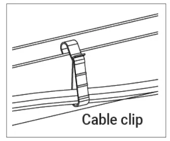
Dress any excess cabling in loops so that it does not contact the roof. Do not form loops smaller than 4.75 inch (12 cm) in diameter.
4.4 Microinverters Connection
Refer to the major installation steps defined in Section 4.2 and listen for a click:
1) when the microinverters are pop out and
2) when AC connectors engage
Inspect the AC connectors to ensure that they are not broken, misshapen, or otherwise degraded prior to connection.
Cover any unused connectors on the AC cable with Enphase Sealing Caps. Listen for a click as the sealing caps engage. 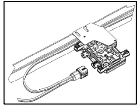
CAUTION! Install sealing caps on all unused AC connectors as these connectors become live when the system is energized. Sealing caps are required for protection against moisture ingress.
Module Mounting
This section contains information for SunPower Type E AC modules; Type G AC and SunPower Type H AC modules. Ensure that you use the correct information for your module type.
The SunPower Limited Warranty for PV Modules is contingent upon modules being mounted in accordance with the requirements described in this section.
5.1 Site Considerations
SunPower modules should only be mounted in locations that meet the following requirements:
Operating Temperature: All SunPower AC modules must be mounted in environments that ensure that the modules will operate within the following maximum and minimum temperatures:
| Max. Operating Cell Temp. | +85°C (+185°F) |
| Max. Ambient Temp. | +50°C (+122°F) |
| Min. Operating Temp. | −40°C (−40°F) |
Design Strength: SunPower Type E, Type G and Type H AC modules are designed to meet a maximum positive (or upward, e.g. wind) and negative (or downward, e.g. static load) design pressure when mounted in the mounting configurations specified in Section 5.2. (Design strength of 2400 Pa corresponds approximately to a wind speed of 130 km/h (81 mph). SunPower AC modules have also been evaluated to UL 1703 for a positive or negative design load of 30 psf.)
Type E. The following image and table show where to mount to the Type E module frame; and defines mounting ranges and the resulting load ratings achieved for each range: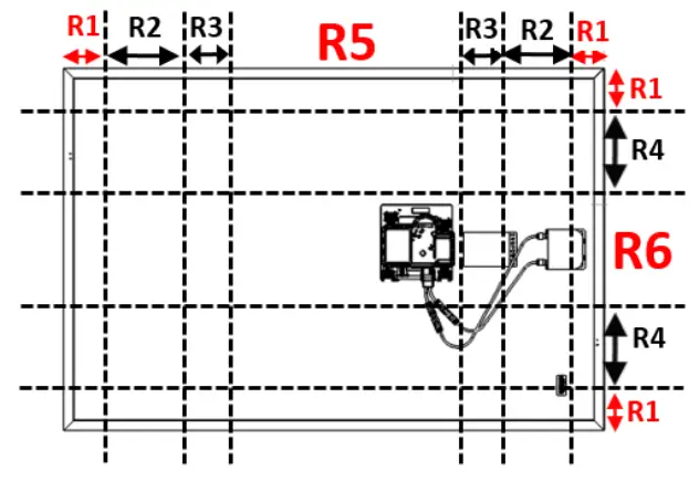
| Mounting Range Tolerance are identical at each module corner in./mm from corner | Load Rating (Pa)* | |
| Wind (up and down) | Snow (down) | |
| R1 0‐2 / 0‐50 | DO NOT MOUNT! | |
| R2 2‐11.8 / 50‐300 | 3000 | 6000 |
| R3 11.8‐15.75 / 300‐400 | 3000 | 6000 |
| R4 2‐14.75 / 50‐375 | 3000 | 3000 |
| R5 | DO NOT MOUNT! | |
| R6 | DO NOT MOUNT! | |
* Design load values may be used as ASD design loads.
Type G and Type H.
Important! The following image and tables show where to mount to the Type G and H module frame and the allowable load ratings corresponding to the mounting zones chosen. To use the tables, identify the two mounting zones in which you wish to mount. You may choose to mount at any location in zones A, B, and C, as long as the mounting points are symmetric about one axis of the module. Identify the combination of mounting zones you have chosen in the table and then refer to the corresponding load rating. Note also that load ratings are different for modules supported by rails; versus systems that attach modules without rails. 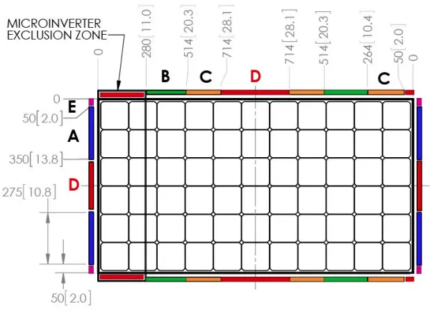
Table1. Mounting Configuration and Load Resistance
| Mounting Method | Mounting (1) | Test/ Design Load (2) | Downward (+) / Upward (‐) Pressure (Pa) (1) | |
| A‐Series/M‐Series | ||||
| Rail Supported | w/o Rail Support | |||
| Top Clamp | BB | Test Load | 8100/‐4050 | 5400/‐3600 |
| Design Load | 5400/‐2700 | 3600/‐2400 | ||
| CC | Test Load | 2400/‐2550 | 2400/‐2400 | |
| Design Load | 1600/‐1700 | 1600/‐1600 | ||
| AA | Test Load | 3600/‐2400 | 2400/‐2400 | |
| Design Load | 2400/‐1600 | 1600/‐1600 | ||
| EE | Test Load | NA | 2400/‐2400 | |
| Design Load | 1600/‐1600 | |||
| Bolt or Mountainous Clamps | BB | Test Load | 9000/‐5400 | 5400/‐5400 |
| Design Load | 6000/‐3600 | 3600/‐3600 | ||
| CC | Test Load | 4200/‐4200 | 3600/‐4200 | |
| Design Load | 2800/‐2800 | 2400/‐2800 | ||
| AA | Test Load | 4500/‐3000 | 3000/‐3000 | |
| Design Load | 3000/‐2000 | 2000/‐2000 | ||
| DD | DO NOT MOUNT | |||
(1) If mounting in multiple zones, must use the lower value of the two zones.
(2) Test loads are evaluated at 1.0 factor of safety, and Design loads are calculated using 1.5 factor of safety (Test load = 1.5 x Design load). Design load values may be used as ASD design loads.
When mounting modules in snow‐prone or high‐wind environments, special care should be taken to mount the modules in a manner that provides sufficient design strength while meeting local code requirements.
Excluded Operating Environments and Reconfigurations
Certain operating environments are not recommended for SunPower AC modules, and are excluded from the SunPower Limited Warranty for these modules. Contact SunPower if there are any unanswered questions concerning the operating environment.
5.2 Mounting Configurations
Modules may be mounted at the appropriate orientation to maximize sunlight exposure.
In order to prevent water from entering the junction box (which could present a safety hazard), modules should be oriented such that the junction box is in the uppermost position and should not be mounted such that the top surface faces downward. In addition, ensure the module orientation also prevents the microinverter from direct exposure to rain, UV and other harmful weather events (ice/snow).
Clearance between the module frame and mounting structure or grade is required to prevent wiring damage and to enable air to circulate behind the module. A minimum of 2″ (5 cm) is required between the module frame and structure or ground.
SunPower AC modules are only NRTL Listed for use when their factory frames are fully intact. Do not remove or alter any module frame. Creating additional mounting holes may damage the module and reduce the strength of the frame.
Modules may be mounted using the following methods only:
- Pressure Clamps or Clips: Mount the module with the clips attached to the longer sides of the module. Refer to the allowable ranges in Section 5.0. Installers must ensure the clamps are of sufficient strength to allow for the maximum design pressure of the module.
- End Mount: End mounting is the capture mounting of the module’s shorter sides to a supporting rail. The end‐mounting rail and clips or clamps must be of sufficient strength to allow for the maximum design pressure of the module. Verify this capacity with the mounting system vendor before installation.
- SunPower, SunPower‐specified, or SunPower‐supplied mounting systems:
Modules mounted with strict adherence to SunPower documentation, using hardware systems supplied by or specified by SunPower.
5.3 Handling of Modules during Installation
Never lift or move the modules using cables or the junction box under any circumstances. Do not place modules face forward in direct contact with abrasive surfaces such as roofs, driveways, wooden pallets, railings, or walls. The front surface of a module is sensitive to oils and abrasive surfaces, which may lead to scratches and irregular soiling.
SunPower recommends handling modules with gloves and not touching the front surface. Any fingerprints resulting from installation can be reduced by following the washing guidelines in Section 6.0. A given module’s product datasheet specifies the glass type it uses.
Before installing the AC module, the microinverters must be lifted from the shipping position, faces you. Using both hands, lift the microinverter up. You will hear four clicks as the microinverter locks into the installation position. Ensure the four latches are locked, and the microinverter is not tilted.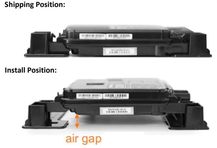
Maintenance
Visually inspect all modules annually to verify the integrity of both the electrical and the mechanical connections; and to verify the absence of corrosion. This visual inspection should be performed by an authorized SunPower Dealer or trained SunPower support personnel.
Periodic cleaning of modules is recommended but is not required. Periodic cleaning has resulted in improved module performance, especially in regions whitlow levels of annual precipitation (fewer than 18.25 inches annually). Consult your Dealer or supplier about recommended cleaning schedules for your area. To clean module, spray it with potable, non‐heated water. Normal water pressure is more than adequate, but pressurized water (up to 1500 psi) may be used. Fingerprints stains, or accumulations of dirt on the front surface of the module may be removes’ follows: rinse the area and wait 5 minutes. Re‐wet the area and then use a soft sponge or seamless cloth to wipe the glass surface in a circular motion. NEVER use harsh cleaning materials such as scouring powder, steel wool, scrapers, blades, or other sharp instruments to clean module glass. Use of such materials on the modules will void the product warranty.
Electrical Characteristics and Grid Interaction
Type E. 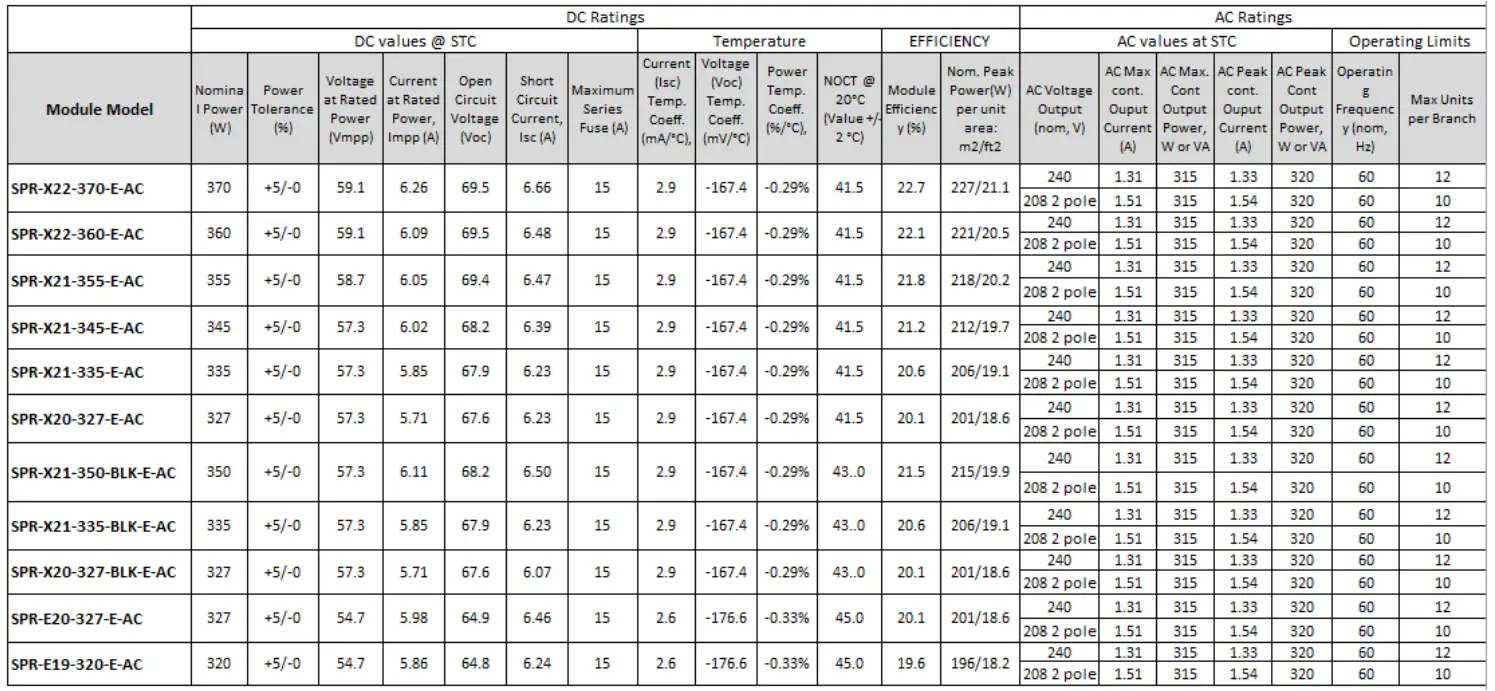
| Voltage and Frequency Limits for Utility Interaction | |||
| Condition | Simulated Source | Maximum Time (sec) at 60 Hazy before cessation of current to the simulated utility | |
| Voltage (V) | Frequency (Hz) | ||
| A | < 0.50 Vnor | Rated | 0.16 |
| B | Rated | 2 | |
| C | Rated | 1 | |
| D | 1.20 Vnor ≤V | Rated | 0.16 |
| E | Rated | f > rated +0.5 | 0.16 |
| F | Rated | f < rated −0.7 | 0.16 |
| G | Volt‐Var | Accuracy | x |
a – Non‐adjustable maximum clearing times
b – Nominal voltage equals 240 V line to line
c – Trip Limit accuracy: Voltage ± 1.0% based on 240 V nominal, frequency ‐ ± 0.1 Hz
| I rms | Total duration | Synchronization in rush current | Trip Time Accuracy |
| 5.8 A | 100 ms | 0.2 A | 20 ms |
Type G. 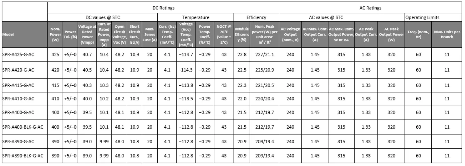
| Voltage and Frequency Limits for Utility Interaction | |||
| Condition | Simulated Source | Maximum Time (sec) at 60 Hazy before cessation of current to the simulated utility | |
| Voltage (V) | Frequency (Hz) | ||
| A | < 0.50 Vnor | Rated | 0.16 |
| B | Rated | 2 | |
| C | Rated | 1 | |
| D | 1.20 Vnor ≤V | Rated | 0.16 |
| E | Rated | f > rated +0.5 | 0.16 |
| F | Rated | f < rated−0.7 | 0.16 |
| G | Volt‐Var | Accuracy | 6% |
a – Non‐adjustable maximum clearing times
b – Nominal voltage equals 240 V line to line
c – Trip Limit accuracy: Voltage ± 1.0% based on 240 V nominal, frequency ‐ ± 0.1 Hz
| I rms | Total duration | Synchronization in rush current | Trip Time Accuracy |
| 5.8 A | 100 ms | 0.2 A | 2 line cycles |
Type H.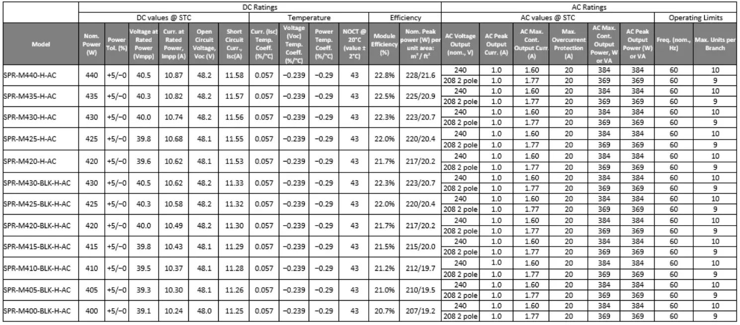
| Voltage and Frequency Limits for Utility Interaction | |||
| Condition | Simulated Source | Maximum Time (sec) at 60 Hazy before cessation of current to the simulated utility | |
| Voltage (V) | Frequency (Hz) | ||
| A | < 0.50 Vnor | Rated | 0.16 |
| B | Rated | 2 | |
| C | Rated | 1 | |
| D | 1.20 Vnor ≤V | Rated | 0.16 |
| E | Rated | f > rated +0.5 | 0.16 |
| F | Rated | f < rated−0.7 | 0.16 |
| G | Volt‐Var | Accuracy | 6% |
a – Non‐adjustable maximum clearing times
b – Nominal voltage equals 240 V line to line
c – Trip Limit accuracy: Voltage ± 1.0% based on 240 V nominal, frequency ‐ ± 0.1 Hz
| I rms | Total duration | Synchronization in rush current | Trip Time Accuracy |
| 5.8 A | 100 ms | 0.2 A | 2 line cycles |
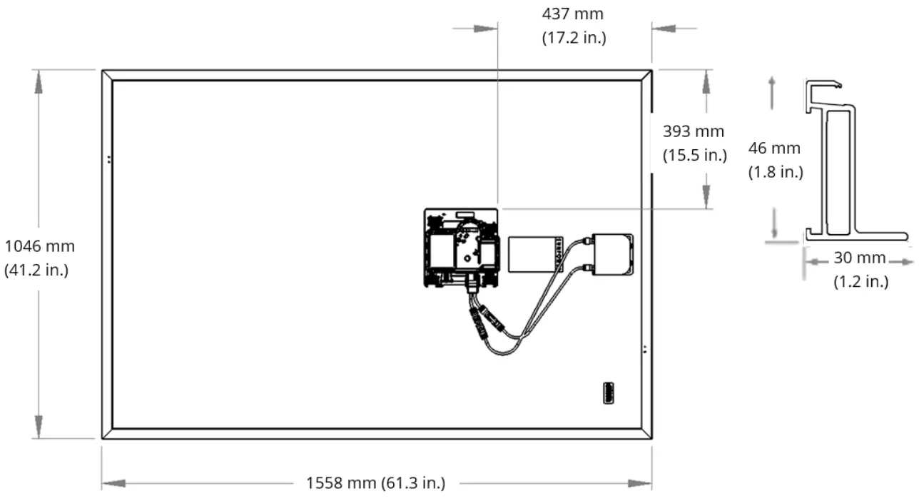
Type G.
 Gen 5.1 Frame Profile
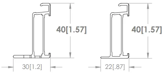
Gen 5.2 Frame Profile
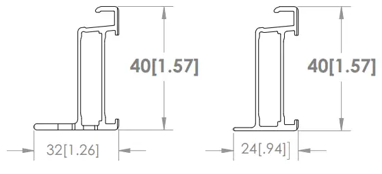
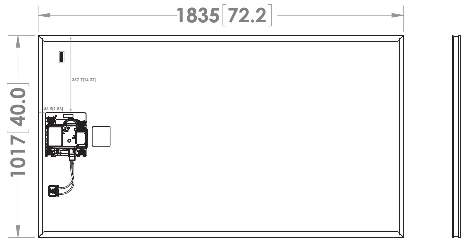
Type H. 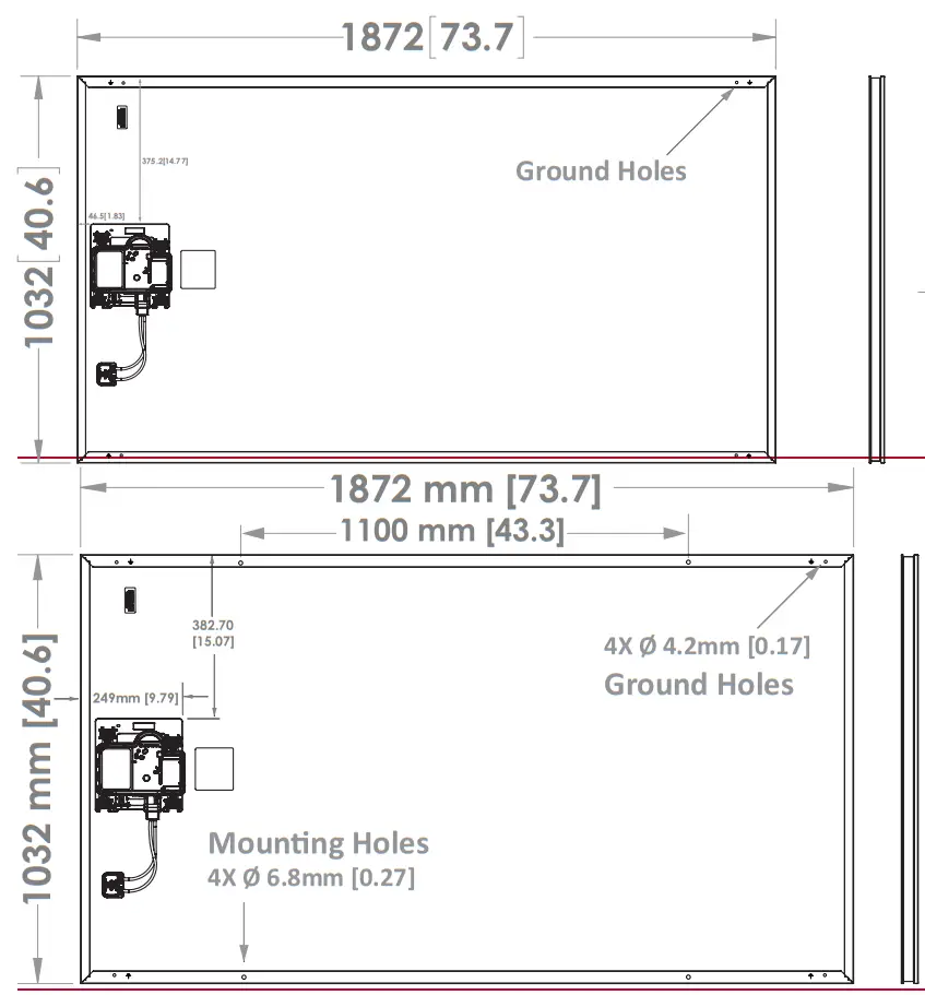
Gen 5.2 Frame Profile

Gen 5.2 Frame Profil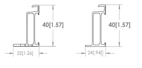
![]() ©2022 SunPower Corporation.
©2022 SunPower Corporation.
All rights reserved. Specifications included
in this document are subject to
change without notice.


