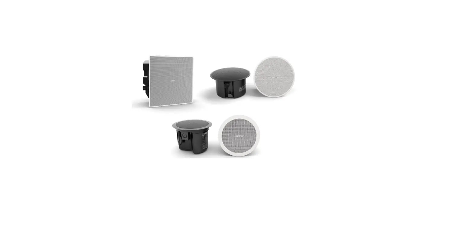
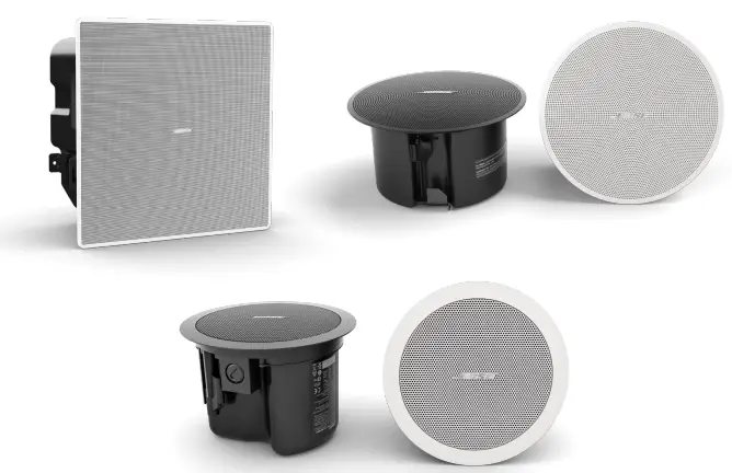
BOSE FS2C In-Ceiling Loudspeakers
In-ceiling Loudspeakers Design Guide
Welcome to the In-ceiling Loudspeakers Design Guide. This guide will provide you with all the necessary information and resources to design a sound system using in-ceiling loudspeakers.
Product Overview
The In-ceiling Loudspeakers Design Guide is divided into three main sections: Introduction, System Design Resources, and Design Guidelines. The Introduction section provides an overview of the guide, while the System Design Resources section provides additional resources for designing your sound system. The Design Guidelines section provides detailed information on how to design your sound system.
Design Guidelines
The Design Guidelines section is divided into five steps:
Step 1: Loudness
Determine the desired loudness level of your sound system.
Step 2: Ceiling Height
Determine the height of your ceiling to choose the appropriate loudspeaker model.
Step 3: Response
Determine the frequency response requirements for your sound system.
Step 4: Coverage
Determine the coverage area of your sound system.
Step 5: Calculate the Required Amplifier Size
Calculate the required amplifier size for your sound system based on the loudspeaker model and coverage area.
Design Worksheet
The Design Worksheet provides a step-by-step guide for choosing the appropriate loudspeaker model for your sound system. The worksheet includes:
- Step 1: Loudness
- Step 2: Ceiling Height
- Step 3: Response
- Step 4: Coverage
- Step 5: Calculate the Required Amplifier Size
Tap Charts
The Tap Charts provide information on the DM2C-LP, FS2C, DM3C, FS4CE, DM5C, and DM6C loudspeaker models.
DM2C-LP
The DM2C-LP loudspeaker model is designed for low ceiling heights and provides a wide coverage area.
FS2C
The FS2C loudspeaker model is designed for high ceiling heights and provides a narrow coverage area.
DM3C
The DM3C loudspeaker model is designed for medium ceiling heights and provides a wide coverage area.
FS4CE
The FS4CE loudspeaker model is designed for high ceiling heights and provides a wide coverage area.
DM5C
The DM5C loudspeaker model is designed for low to medium ceiling heights and provides a wide coverage area.
DM6C
The DM6C loudspeaker model is designed for medium to high ceiling heights and provides a wide coverage area.
Product Usage Instructions
To use the in-ceiling loudspeakers, follow these instructions:
- Determine the desired loudness level of your sound system.
- Determine the height of your ceiling to choose the appropriate loudspeaker model.
- Determine the frequency response requirements for your sound system.
- Determine the coverage area of your sound system.
- Calculate the required amplifier size for your sound system based on the loudspeaker model and coverage area.
- Choose the appropriate loudspeaker model based on the ceiling height and coverage area.
- Install the loudspeakers in the ceiling according to the manufacturer’s instructions.
- Connect the loudspeakers to the amplifier according to the manufacturer’s instructions.
- Test the sound system and make any necessary adjustments.
Overview
Introduction
- Using this design guide, you will be able to create designs for applications that utilize in-ceiling loudspeakers. We offer additional design guides for surface-mount and pendant-mount loudspeakers, as well as dedicated design guides for EdgeMax and FreeSpace 3 sub-satellite systems. To learn more about our loudspeakers and technology capabilities, as well as access additional trainings and tutorials, visit proedu.Bose.com/learn.
System Design Resources
- In addition to this guide, we offer the following tools at PRO.BOSE.COM on the software and individual loudspeaker product pages:
- Bose Modeler: advanced acoustical design simulation tool, with direct and reflected energy, and Speech Transmission Index (STI). Free at pro.Bose.com/modeler
- Bose Business Music System Designer: Web-based auto-loudspeaker layout tool. Free at
pro.Bose.com/BMSD - EASE .gll files: for use in the AFMG EASE application, and the EASE GLL Viewer application. EASE allows the simulation of reverberation times, speech intelligibility, and other acoustical parameters. EASE is a paid download. EASE GLL Viewer is free.
- EASE Address files: for use in the AFMG EASE Address (2D tool, direct field coverage) or EASE Evac. EASE Address is free.
- BIM files: includes the Revit format. Revit is a paid download.
- All system designs begin with a set of requirements. The system requirements can be as simple as, “it has to sound great” or as detailed as, “it must play background-level music at 5 dB above the ambient noise level of the restaurant’s main dining room, which is 65 dB.” The challenge is to gather the right set of requirements, and then turn them into a set of criteria that you can use to create your design. It is important to remember that you are the designer and should use your own intuition and decision skills when planning a project in addition to calculations. Applications with mounting heights between 2.4 meters and 10 meters (8 feet and 32 feet) are supported through the in-ceiling loudspeaker models listed in this guide.
- There are four key requirements that need to be identified to deliver the right system:
- Loudness: What sound pressure level (SPL) is required for this application?
- Ceiling Height: What loudspeakers will work best for my room’s ceiling height?
- Response: What bandwidth is required for the type of program material that will be used?
- Coverage: How consistent must the sound be across the entire coverage area?
- Each of these requirements can be easily converted into a specification that we can use to create our system design. If we understand the customer’s needs in these four areas, we can deliver a design that will—at a minimum—meet their needs and—at best—exceed their expectations.
- For the purposes of this design guide, we will assume that you are familiar with the system requirements for a commercial audio system and are ready to focus on loudspeaker selection, creation of a loudspeaker layout, and defining the necessary amplifier power needed to power the design.
Design Guidelines
- When creating a design, you should consider the following:
- Ceiling Height
- Maximum SPL for the application (for example 70 dB-SPL, Z-weighted)
Design Worksheet
- Use the following worksheet to create a design using Bose Professional loudspeakers.
Choosing a Model
- Step 1: Loudness
Maximum SPL Capability
- Confirm that your chosen loudspeaker model will meet your loudness requirement. Find your ceiling height and follow the column down until you reach your desired maximum continuous output level. Models with a higher sensitivity and higher tap settings will be able to play at higher levels. Individual model tap charts are available at the end of this document.
- Example: For a ceiling height of 5 meters (16 feet) in a project that requires 90 dB, you would choose FS4CE.
| In-ceiling Models: Maximum Continuous Output Level | ||||||||||||||
| Ceiling Height | m | 2.4 | 2.7 | 3 | 3.7 | 4 | 4.3 | 5 | 5.5 | 6 | 6.7 | 8 | 9.8 | |
| ft | 8 | 9 | 10 | 12 | 13 | 14 | 16 | 18 | 20 | 22 | 26 | 32 | ||
| DM2C-LP | 9W tap | 94 | 92 | 90 | 87 | 86 | 85 | 83 | 82 | 80 | 79 | 77 | 75 |
dB-SPL |
| 16W / 16Ώ | 97 | 94 | 92 | 89 | 88 | 87 | 85 | 84 | 83 | 82 | 80 | 78 | ||
| DM3C | 25W | 98 | 95 | 93 | 90 | 89 | 88 | 86 | 85 | 84 | 83 | 81 | 79 | |
| FS2C | 16W | 99 | 96 | 94 | 91 | 90 | 89 | 87 | 86 | 85 | 84 | 82 | 84 | |
| FS4CE | 40W | 105 | 102 | 100 | 97 | 96 | 95 | 93 | 92 | 91 | 90 | 88 | 86 | |
| DM5C | 50W | 105 | 102 | 100 | 97 | 96 | 95 | 93 | 92 | 91 | 90 | 88 | 86 | |
| DM6C | 80W | 108 | 105 | 103 | 100 | 99 | 98 | 96 | 95 | 94 | 93 | 91 | 89 | |
| 100W / 8Ώ | 109 | 106 | 104 | 101 | 100 | 99 | 97 | 96 | 95 | 94 | 92 | 90 | ||
| DM8C | 80W | 111 | 108 | 106 | 103 | 102 | 101 | 99 | 98 | 97 | 96 | 94 | 92 | |
| 125W / 8Ώ | 113 | 110 | 108 | 105 | 104 | 103 | 101 | 100 | 99 | 98 | 96 | 94 | ||
Note: The above table assumes standing ear height at 1.5 meters (5 feet), in minimum overlap configuration. Room reverberation could add as much as 4 dB system gain, which is not factored into the measurements above. The use of the transformer on 70/100V systems will introduce an insertion loss of 1 to 2 dB.
Step 2: Ceiling Height
Average Conical Coverage and Woofer Sizes
Smaller woofer models have wider average conical coverage and provide better results in low ceilings. Larger woofer models with narrower average coverage angles are better suited for higher ceilings. Choose the models that will work with your ceiling heights and rule out the other models.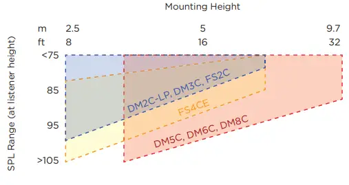
| Woofer Size | Model | Sensitivity (dB) | Highest Tap / Power Handling | Recommended Ceiling Heights |
| 2″–4″ | DM2C-LP (70/100V) | 84 | 9W | 2.5 m–6.1 m (8’–20′) |
| DM2C-LP (16Ώ) | 16W | |||
| DM3C | 83 | 25W | ||
| FS2C | 86 | 16W | ||
| FS4CE | 88 | 40W | ||
| 5″–8″ | DM5C | 87 | 50W | 3 m–10 m (10’–32′) |
| DM6C (70/100V) | 88 | 80W | ||
| DM6C (8Ώ) | 100W | |||
| DM8C (70/100V) | 91 | 80W | ||
| DM8C (8Ώ) | 125W |
Step 3: Response
Confirm that the chosen loudspeaker will meet your low-frequency response requirement.
| Vocal-range | Low Frequency (–10 dB) | Full-range | Low Frequency (–10 dB) | Extended- range | Low Frequency (–10 dB) | ||
| DM2C-LP | 85 Hz | FS4CE | 70 Hz | FreeSpace 3 system | 40 Hz | ||
| FS2C | 83 Hz | DM5C | 65 Hz | EdgeMax EM90/EM180 | 45 Hz | ||
| DM3C | 75 Hz | DM6C | 59 Hz | ||||
| DM8C | 52 Hz | Any vocal- range or full-range loudspeaker combined with DM8C-SUB subwoofer | 38 Hz |
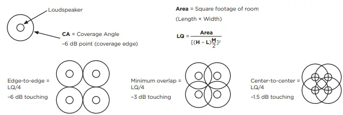
Step 4: Coverage
Determining Loudspeaker Quantity and Spacing
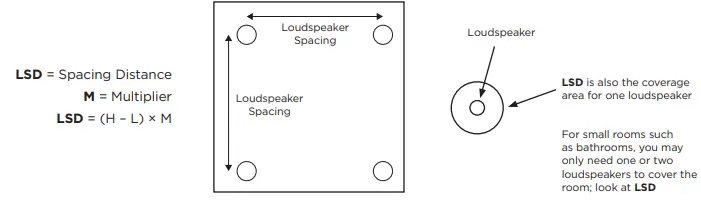
The goal is to fill a rectangle-shaped room with coverage circles at your desired density. Using the graph paper on the last page, create a sketch layout of the room. Using your sketch of the room, follow the steps below to create a layout with the loudspeaker spacing that meets your coverage requirement. Calculators or software can simplify this process. Medium-sized or larger distributed installed systems for background music or voice typically have four or more ceiling loudspeakers in a room. Use Loudspeaker Spacing Distance (LSD) for small rooms that only need one.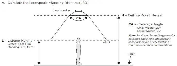
| 2″–4″ Small Woofer Coverage | M (multiplier) | Models | 5″–8″ Large Woofer Coverage | M (multiplier) | Models | |
| Edge-to-edge | 3.46 | FS2C DM2C-LP DM3C FS4CE | Edge-to-edge | 2.61 | DM5C DM6C DM8C | |
| Minimum Overlap | 2.45 | Minimum Overlap | 1.84 | |||
| Center-to-center | 1.73 | Center-to-center | 1.30 |
- Multipliers are created from Coverage Angles (CA). These are multipliers we have found to work for most applications. For more precise results, and to adjust for obstructions, use Bose Modeler, EASE, EASE Address, EASE Evac, or another calculator.
- Edge-to-edge coverage can provide fidelity in fixed-location seating/standing and can generally work well for installations on a budget. It also works well for ambient-level and low-level background music. Center-to-center installations will have higher density and can accommodate people listening in many different positions and moving floor plans due to uniform coverage. They will also have fewer dead zones. Minimum overlap (or center-to-center) may also be needed if critical communication is happening over the system. Bose Modeler or EASE Evac can help with speech intelligibility evaluation.
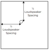
- B. Place the first loudspeaker at ½ LSD from any corner of the room.

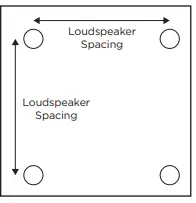
- C. The remaining loudspeakers are arranged on a square grid pattern using the LSD. If a loudspeaker would be placed on or beyond the perimeter of the room, delete that row/column of loudspeakers.

- D. After the last loudspeaker is placed, center the loudspeakers in that row to create new offset distances out from each wall, which may be unique from ½ LSD.
- E. (Optional) To quickly calculate the total Loudspeaker Quantity (LQ) needed to fill the rectangular room without using graph paper, follow this method. In square layouts, the final total is sometimes slightly reduced as you lay out rows. You can also determine final quantity by following Step B on graph paper until the room is filled.

Subwoofers: Quantity and Placement of Subwoofers
- The number of subwoofers to use, where to position them, and how loud to set them can vary depending on the individual situation. Details such as placement, boundary loading, room size, coupling quantity of multiple loudspeakers to subwoofers, type of music, type of activity, budget, and the expectations of the listeners should all be considered. The following guidelines are general rules to follow.
- Add one subwoofer for every group of four vocal- or full-range loudspeakers.
- Subwoofer spacing should be as far apart as is practical. 12.2 meters (40 feet) or greater subwoofer-to-subwoofer spacing distance within the same zone is desirable.
- When the suggested subwoofer count is two within a single zone, it may be preferable to use either one in a corner to avoid audible interference; or increase the count to three, which creates more audible interference locations but limits them to smaller sizes where the reverberant field (added room reflections) tends to mask them.
- Placing a ceiling subwoofer within 0.9 meters (3 feet) of a wall increases its output by 3 dB. Placing it within 0.9 meters (3 feet) of a corner increases its output by another 3 dB (6 dB total) and also reduces reflections that can create audible interference (bass cancellations) in the listening area.
- Listening positions located below the subwoofer should be supported by a nearby vocal- or full-range loudspeaker to provide better tonal balance in the low-frequency pressure zone.
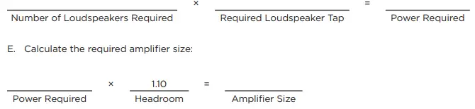
Step 5: Calculate Required Amplifier Size
- All FreeSpace FS, DesignMax, and EdgeMax loudspeakers are compatible with 70-volt, 100-volt, and low-impedance amplifiers.
Use the Tap Charts to determine which loudspeaker tap is required for this design
- A. Locate the loudspeaker tap chart and find the column for mounting height for this design.
- B. Follow the column to the desired maximum SPL.
- C. Follow the row across the chart to determine the required loudspeaker tap.
- D. Calculate the required amplifier power:

Amplifiers: Example Amplifier Configurations
- Modern amplifiers come in a variety of channel counts and configuration options to allow for different output configurations, zoning options, and varying loudspeaker quantities. A properly optimized system may only need a low 1- or 2-watt tap setting to achieve 70 dB in a typical room. The below example lists how many FS2C loudspeakers can be handled at the loudspeaker’s highest 70/100V tap setting.
| FreeSpace FS2C Loudspeaker | Maximum Loudspeakers at Higher Tap Settings | EQ Preset | Average SPL* |
| Amplifier Example | |||
| FreeSpace IZA 190-HZ | 5 at 16W, 10 at 8W tap | FS2C/SE/P |
87 dB at 16W, 84 dB at 8W |
| FreeSpace IZA 2120-HZ | 5 at 16W, 13 at 8W | FS2C/SE/P | |
| PowerShare PS404D | 22 at 16W, 45 at 8W | FS2C | |
| PowerSpace P4150+ | 8 at 16W, 17 at 8W | FS2C |
- 3 meter (10 foot) ceiling height room with edge-to-edge density, standing listener, 12 dB crest factor of pink noise/compressed music, direct-field, no room gain.
SmartBass: Application of SmartBass processing
- If your design is using a PowerSpace+ amplifier; or your design utilizes a dedicated Bose DSP, such as the Commercial Sound Processor CSP models; or any of the ControlSpace ESP or EX models; you have the option of applying SmartBass to your loudspeaker output channel. This uses Bose EQ presets, dynamic EQ, and excursion limiting tuned to each model and room calibration. This will prevent lower background-level music from sounding thin, but also ensures the sound is consistent at various SPL levels. At louder levels, SmartBass also allows for more musical limiting than traditional voltage limiters.
Tap Charts
Individual Loudspeaker Continuous Output Level
- Note: The following tap charts assume standing ear height at 1.5 meters (5 feet) in minimum overlap spacing.
- Room reverberation could add as much as 4 dB system gain, which is not factored into the measurements.
- Designing without room gain will ensure you don’t under-plan your design, and amp attenuation is possible at the job site if you exceed the average room SPL target during measurement. Values below 70 dB are omitted, select a higher tap.
DM2C-LP
| DM2C-LP (standing listener height) | ||||||||||||||
| Ceiling Height | m | 2.4 | 2.7 | 3 | 3.7 | 4 | 4.3 | 5 | 5.5 | 6 | 6.7 | 8 | 9.8 | |
| ft | 8 | 9 | 10 | 12 | 13 | 14 | 16 | 18 | 20 | 22 | 26 | 32 | ||
|
TAP | 1.2W | 85 | 83 | 81 | 78 | 77 | 76 | 74 | 73 | 72 | 70 | — | — |
dB-SPL |
| 2.3W | 88 | 86 | 84 | 81 | 80 | 79 | 77 | 76 | 74 | 73 | 71 | — | ||
| 4.5W | 91 | 89 | 87 | 84 | 83 | 82 | 80 | 79 | 77 | 76 | 74 | 72 | ||
| 9W | 94 | 92 | 90 | 87 | 86 | 85 | 83 | 82 | 80 | 79 | 77 | 75 | ||
| 16Ώ | 97 | 94 | 92 | 89 | 88 | 87 | 85 | 84 | 83 | 82 | 80 | 78 | ||
FS2C
| FS2C (standing listener height) | ||||||||||||||
| Ceiling Height | m | 2.4 | 2.7 | 3 | 3.7 | 4 | 4.3 | 5 | 5.5 | 6 | 6.7 | 8 | 9.8 | |
| ft | 8 | 9 | 10 | 12 | 13 | 14 | 16 | 18 | 20 | 22 | 26 | 32 | ||
|
TAP | 1W | 87 | 84 | 82 | 79 | 78 | 77 | 75 | 74 | 73 | 72 | — | — |
dB-SPL |
| 2W | 90 | 87 | 85 | 82 | 81 | 80 | 78 | 77 | 76 | 75 | 73 | 75 | ||
| 4W | 93 | 90 | 88 | 85 | 84 | 83 | 81 | 80 | 79 | 78 | 76 | 78 | ||
| 8W | 96 | 93 | 91 | 88 | 87 | 86 | 84 | 83 | 82 | 81 | 79 | 81 | ||
| 16W | 99 | 96 | 94 | 91 | 90 | 89 | 87 | 86 | 85 | 84 | 82 | 84 | ||
| 8Ώ | 99 | 96 | 94 | 91 | 90 | 89 | 87 | 86 | 85 | 84 | 82 | 80 | ||
DM3C
| DM3C (standing listener height) | ||||||||||||||
| Ceiling Height | m | 2.4 | 2.7 | 3 | 3.7 | 4 | 4.3 | 5 | 5.5 | 6 | 6.7 | 8 | 9.8 | |
| ft | 8 | 9 | 10 | 12 | 13 | 14 | 16 | 18 | 20 | 22 | 26 | 32 | ||
|
TAP | 3W | 88 | 86 | 84 | 81 | 80 | 79 | 77 | 76 | 75 | 73 | 72 | — |
dB-SPL |
| 6W | 91 | 89 | 87 | 84 | 83 | 82 | 80 | 79 | 78 | 76 | 75 | 72 | ||
| 12W | 94 | 92 | 90 | 87 | 86 | 85 | 83 | 82 | 81 | 79 | 78 | 75 | ||
| 25W | 98 | 95 | 93 | 90 | 89 | 88 | 86 | 85 | 84 | 83 | 81 | 79 | ||
| 8Ώ | 98 | 95 | 93 | 90 | 89 | 88 | 86 | 85 | 84 | 83 | 81 | 79 | ||
FS4CE
| FS4CE (standing listener height) | ||||||||||||||
| Ceiling Height | m | 2.4 | 2.7 | 3 | 3.7 | 4 | 4.3 | 5 | 5.5 | 6 | 6.7 | 8 | 9.8 | |
| ft | 8 | 9 | 10 | 12 | 13 | 14 | 16 | 18 | 20 | 22 | 26 | 32 | ||
|
TAP | 2.5W | 93 | 90 | 88 | 85 | 84 | 83 | 81 | 80 | 79 | 78 | 76 | 74 |
dB-SPL |
| 5W | 96 | 93 | 91 | 88 | 87 | 86 | 84 | 83 | 82 | 81 | 79 | 77 | ||
| 10W | 99 | 96 | 94 | 91 | 90 | 89 | 87 | 86 | 85 | 84 | 82 | 80 | ||
| 20W | 102 | 99 | 97 | 94 | 93 | 92 | 90 | 89 | 88 | 87 | 85 | 83 | ||
| 40W | 105 | 102 | 100 | 97 | 96 | 95 | 93 | 92 | 91 | 90 | 88 | 86 | ||
| 8Ώ | 105 | 102 | 100 | 97 | 96 | 95 | 93 | 92 | 91 | 90 | 88 | 86 | ||
DM5C
| DM5C (standing listener height) | ||||||||||||||
| Ceiling Height | m | 2.4 | 2.7 | 3 | 3.7 | 4 | 4.3 | 5 | 5.5 | 6 | 6.7 | 8 | 9.8 | |
| ft | 8 | 9 | 10 | 12 | 13 | 14 | 16 | 18 | 20 | 22 | 26 | 32 | ||
|
TAP | 3W | 92 | 90 | 88 | 85 | 84 | 83 | 81 | 80 | 79 | 77 | 76 | 73 |
dB-SPL |
| 6W | 95 | 93 | 91 | 88 | 87 | 86 | 84 | 83 | 82 | 80 | 79 | 76 | ||
| 12W | 98 | 96 | 94 | 91 | 90 | 89 | 87 | 86 | 85 | 83 | 82 | 79 | ||
| 25W | 102 | 99 | 97 | 94 | 93 | 92 | 90 | 89 | 88 | 87 | 85 | 83 | ||
| 50W | 105 | 102 | 100 | 97 | 96 | 95 | 93 | 92 | 91 | 90 | 88 | 86 | ||
| 8Ώ | 105 | 102 | 100 | 97 | 96 | 95 | 93 | 92 | 91 | 90 | 88 | 86 | ||
DM6C
| DM6C (standing listener height) | ||||||||||||||
| Ceiling Height | m | 2.4 | 2.7 | 3 | 3.7 | 4 | 4.3 | 5 | 5.5 | 6 | 6.7 | 8 | 9.8 | |
| ft | 8 | 9 | 10 | 12 | 13 | 14 | 16 | 18 | 20 | 22 | 26 | 32 | ||
|
TAP | 2.5W | 93 | 90 | 88 | 85 | 84 | 83 | 81 | 80 | 79 | 78 | 76 | 74 |
dB-SPL |
| 5W | 96 | 93 | 91 | 88 | 87 | 86 | 84 | 83 | 82 | 81 | 79 | 77 | ||
| 10W | 99 | 96 | 94 | 91 | 90 | 89 | 87 | 86 | 85 | 84 | 82 | 80 | ||
| 20W | 102 | 99 | 97 | 94 | 93 | 92 | 90 | 89 | 88 | 87 | 85 | 83 | ||
| 40W | 105 | 102 | 100 | 97 | 96 | 95 | 93 | 92 | 91 | 90 | 88 | 86 | ||
| 80W | 108 | 105 | 103 | 100 | 99 | 98 | 96 | 95 | 94 | 93 | 91 | 89 | ||
| 8Ώ | 109 | 106 | 104 | 101 | 100 | 99 | 97 | 96 | 95 | 94 | 92 | 90 | ||
DM8C
| DM8C (standing listener height) | ||||||||||||||
| Ceiling Height | m | 2.4 | 2.7 | 3 | 3.7 | 4 | 4.3 | 5 | 5.5 | 6 | 6.7 | 8 | 9.8 | |
| ft | 8 | 9 | 10 | 12 | 13 | 14 | 16 | 18 | 20 | 22 | 26 | 32 | ||
|
TAP | 2.5W | 96 | 95 | 107 | 104 | 103 | 102 | 101 | 99 | 98 | 97 | 95 | 93 |
dB-SPL |
| 5W | 99 | 96 | 94 | 91 | 90 | 89 | 87 | 86 | 85 | 84 | 82 | 80 | ||
| 10W | 102 | 99 | 97 | 94 | 93 | 92 | 90 | 89 | 88 | 87 | 85 | 83 | ||
| 20W | 105 | 102 | 100 | 97 | 96 | 95 | 93 | 92 | 91 | 90 | 88 | 86 | ||
| 40W | 108 | 105 | 103 | 100 | 99 | 98 | 96 | 95 | 94 | 93 | 91 | 89 | ||
| 80W | 111 | 108 | 106 | 103 | 102 | 101 | 99 | 98 | 97 | 96 | 94 | 92 | ||
| 8 Ώ | 113 | 110 | 108 | 105 | 104 | 103 | 101 | 100 | 99 | 98 | 96 | 94 | ||