![]()
OPERATOR’S MANUAL
KSPLS15-HITCH Kit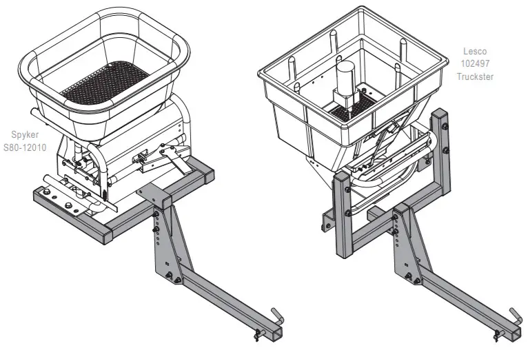
For use with the Spyker or Lesco Electric Spreaders
Spyker Spreaders
Contact us at 800.972.6130
www.spyker.com
![]() IMPORTANT
IMPORTANT
This manual contains information for the safety of persons and property.
Read it carefully before the assembly and operation of the equipment!
SAFETY
Understanding the Machine Safety Labels
The machine safety labels shown in this section are placed in important areas on your machine to draw attention to potential safety hazards.
On your machine safety labels, the words DANGER, WARNING, and CAUTION are used with this safety-alert symbol.
DANGER identifies the most serious hazards.
The operator’s manual also explains any potential safety hazards whenever necessary in special safety messages that are identified with the word CAUTION and the safety-alert symbol.
Safety Alert Symbol
Safely Labels on Hitch
OPERATING SAFELY
General
- Read this manual and the manual of the vehicle you are attaching the hitch and spreader onto. Be thoroughly familiar with the controls and the proper use of the equipment. Know how to stop the vehicle and disengage the controls quickly.
- The spreader is intended for use in lawn care and snow/ice melt applications only.
- Do not use for applications other than those intended by the manufacturer.
- Do not let an untrained person or children operate the spreader.
- Do not let anyone, especially children, rides on the hitch or the spreader. Riders are subject to injury such as being struck by foreign objects and being thrown off. Riders may also obstruct the operator’s view, resulting in the vehicle being operated in an unsafe manner.
- Keep bystanders away when you operate spreader.
- Keep hands, feet, clothing, hair, and loose items away from any moving parts. Failure to check could cause personal injury.
- To prevent injury to the hand:
– Never place hands into a hopper or adjust Accuway Directional Control while the motor is running.
– If using hand to open or close gate actuator, use extension.
Personal Protective Equipment
- Always wear ear and eye protection when operating the spreader.
- Wear appropriate clothing, footwear, and safety equipment when operating the spreader.
- Do not operate the spreader when barefoot or wearing open sandals.
This Spreader is designed to be attached to 4-Wheel Vehicles only
While significant effort was made to ensure that the recommended vehicles are safe for operation, it is up to the operator to use the spreader and vehicle with the following safe operating practices.
- When the spreader is attached to a vehicle, be aware that the handling characteristics of the vehicle may be affected. To prevent loss of control when the spreader is attached to the vehicle.
– Read spreader Operators Manual.
– Allow for longer braking distances.
– Vehicle speed should be less than 10mph. Speed should always be slow enough to maintain control.
If your vehicle manual specifies a speed slower than 10 mph when carrying loads, then do not exceed the specified speed.
– Do not drive on slopes greater than 10 degrees.
– Empty spreader hopper and travel slowly while going up and down trailer ramps. - Do not drive on wet slopes. Slippery conditions reduce traction and could cause loss of control.
- Look behind the machine before you back up. Back up carefully.
- Travel slowly over rough terrain.
- Do not load spreader hopper with more than the maximum weight capacity.
- Do not operate without securing the spreader to the vehicle with the supplied ratchet straps.
UTV – Mounting Hitch to Utility Terrain Vehicle
The following UTV specifications are recommended. Review your Vehicle Operators Manual for your vehicle specifications.
- Must have a 2.0″ receiver hitch or an adaptor to accept a 2.0″ receiver hitch AND
- Minimum vehicle dry weight of 1050 lb AND
- The minimum wheelbase of 70.9″ AND
- The minimum payload capacity of 800lb AND
- Vehicle tire pressure is at the manufacturer’s recommended settings AND
- The Gross Vehicle Weight (GVW) must never exceed the Gross Vehicle Weight Rating (GVWR) of the machine. Failure to do so may limit machines handling characteristics.
To calculate GVW, add the following:
(A) Empty Vehicle Weight (Full fluids. See vehicle operators manual)
(B) Occupant Weight (Driver + Passenger if applicable)
(C) Cargo Box Load Weight
(Do not exceed maximum cargo box capacity)
(D) Optional Vehicle Accessories Weight (Cab, snow blade, etc)
(E) Spreader Weight (See capacities section)
(F) Weight of Material in Hopper (Do not exceed Hopper Capacity. See Capacity Section)
(G) Weight of Spreader Mount
GVW = A + B + C + D + E + F + G
NOTE: GVW must be lower than GVWR (See Vehicle Operators Manual for rating). If not, do not operate a vehicle and reduce the weight until GVW is lower than GVWR.
Recommended UTV Models
Reference the below UTV model chart for the vehicles that the KSPLS15-HITCH is recommended for:
UTV Model Chart for KSPLS15-HITCH
| UTV Make | UTV Model |
| Polaris | Ranger 800 EFI HO |
| Ranger 400 | |
| Ranger 800 | |
| Ranger 900 | |
| Deere | XUV Sport RSX |
| XUV 550 Camo | |
| XUV 550 s4 | |
| Kubota | RTV 500 |
| RTV 1100 | |
| RTV X |
NOTE:
- It is not recommended that the KSPLS15-HITCH be used on a make or model UTV that is not listed.
- For questions regarding the fit up to UTV makes and models not listed contact Spyker customer service at 800-972-6130
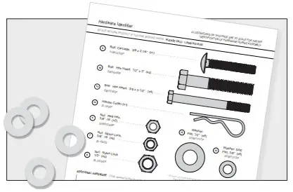
Hardware Identifier
ILLUSTRATIONS ON THIS PAGE ARE TO SCALE FOR FASTER IDENTIFICATION OF HARDWARE DURING ASSEMBLY.
DO NOT RETURN THE PRODUCT IF YOU ARE MISSING PARTS. PLEASE CALL: 1 (800) 972-6130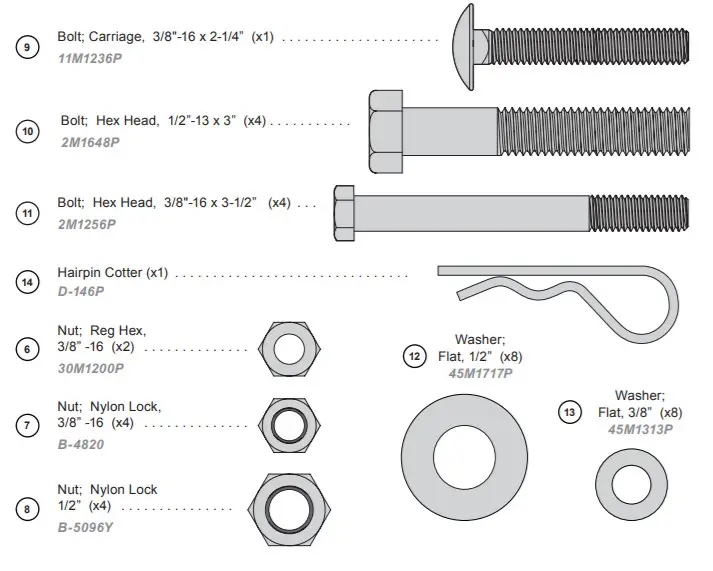
![]() * Exterior circumference of washers can vary. These dimensions are a measurement of the internal diameter of the washer.
* Exterior circumference of washers can vary. These dimensions are a measurement of the internal diameter of the washer.
ADDITIONAL HARDWARE ( Only needed for the Lesco Hitch )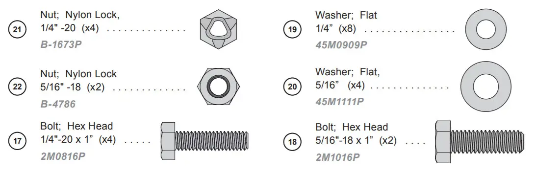
Part List
FOR MOUNTING SPYKER OR LESCO SPREADER
| No. | Part # | Description | Qty |
| 1 | 1009630 | Hitch Tube | 1 |
| 2 | 1009722 | Plate Weldment; Adjustment | 1 |
| 3 | 1019555 | Universal Mount with Reflectors | 1 |
| 1019549 | Hardware Bag | 1 | |
| 4 | 1001569 | Plug Sq; Plastic, 2″ | 6 |
| 5 | 1007748-01 | Pin; Hitch-Plated | 1 |
| 6 | 30M1200P | Nut; Reg Hex, 3/8″ -16 | 2 |
| 7 | B-4820 | Nut; Nylon Lock, 3/8″ -16 | 4 |
| 8 | B-5096Y | Nut, Nylon Lock, 1/2″ -13 | 4 |
| 9 | 11M1236P | Bolt; Carriage, 3/8″-16 x 2-1/4″ | 1 |
| 10 | 2M1648P | Bolt; Hex Head, 1/2″-13 x 3″ | 4 |
| 11 | 2M1256P | Bolt; Hex Head, 3/8″-16 x 3-1/2″ | 4 |
| 12 | 45M1717P | Washer; Flat, 1/2″ | 8 |
| 13 | 45M1313P | Washer; Flat, 3/8″ | 8 |
| 14 | D-146P | Cotter; Hairpin, 1/8″ #211 | 1 |
| 15 | 1019518-10 | Left Adapter; Lesco, Painted | 1 |
| 16 | 1019521-10 | Right Adapter; Lesco, Painted | 1 |
| 1019550 | Additional Hardware Bag | 1 | |
| 17 | 2M0816P | Bolt; Hex Head, 1/4″-20 x 1″ | 4 |
| 18 | 2M1016P | Bolt; Hex Head, 5/16″-18 x 1″ | 2 |
| 19 | 45M0909P | Washer; Flat, 1/4″ | 8 |
| 20 | 45M1111P | Washer; Flat, 5/16″ | 4 |
| 21 | B-1673P | Nut; Nylon Lock, 1/4″ -20 | 4 |
| 22 | B-4786 | Nut; Nylon Lock, 5/16″ -18 | 2 |
These Additional Parts are only needed for attaching to a LESCO Spreader > They’re unnecessary for a Spyker Assembly.
Part Explosion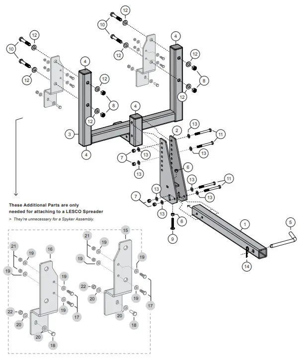
Assembly
- Identifying Hardware
For reassurance, lay the nuts, bolts, and washers down on page 5 to verify you’re using the correct parts during assembly.
- Hitch Assembly Steps and Mounting to UTV Steps
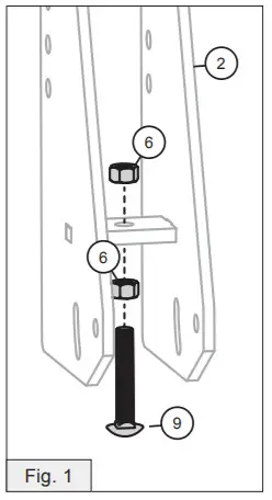
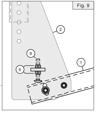
Insert the hitch tube (1) into the UTV receiver and lock it in place using the hitch pin (5) and the cotter pin (14). - Add a 3/8″ hex nut (6) to the 3/8″ x 2-1/4 carriage bolt (9). Slide this bolt through the adjustment plate (2) using the remaining 3/8″ nut (6).
NOTE: Move the carriage bolt (9) up as far as possible so it will be out of the way.
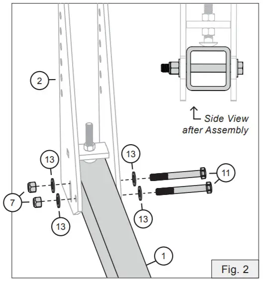
- Slide the hitch tube (1) into the adjustment plate (2) at the base, as illustrated here.
Add a 3/8″ washer (13) to two 3/8 hex bolts (11).
Run these bolts through the adjustment plate (2) and the hitch tube (1). Secure with another 3/8″ washer (13) and 3/8″ nylon lock nut (7). Tighten the bolts down.
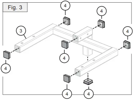
- Insert the six plastic square plugs (4) into the openings of the spreader mount (3).

- Adding Spreader Mount
The assembly process for the next few steps will vary depending on the brand of spreader you’re using:
SPYKER
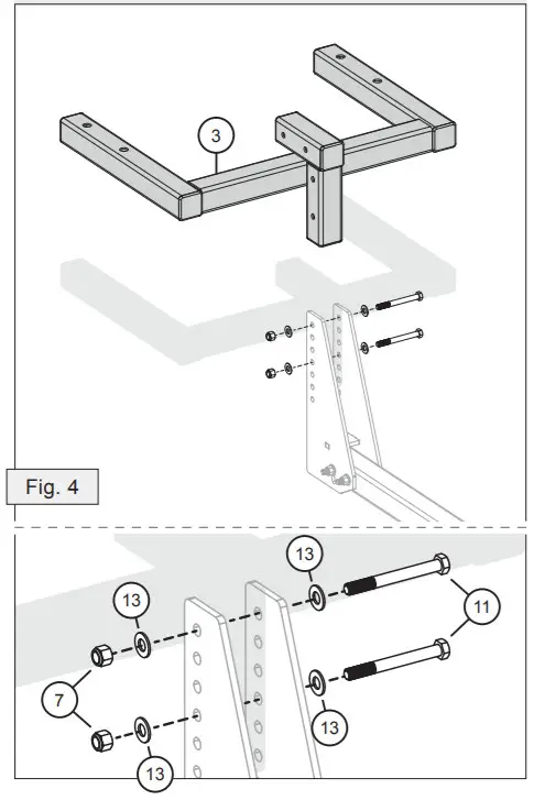
Align the spreader mount (3) with the adjustment plate (2) as illustrated below. (Fig. 4) Add a 3/8″ washer (13) to two 3/8 hex bolts (11).
Run these bolts through the adjustment plate (2) and the spreader mount (3). Secure with another 3/8″ washer (13) and 3/8″ nylon lock nut (7). Tighten the bolts down. LESCO
LESCO
Align the spreader mount (3) with the adjustment plate (2) as illustrated below. (Fig. 5) Add a 3/8″ washer (13) to two 3/8 hex bolts (11).
Run these bolts through the adjustment plate (2) and the spreader mount (3). Secure with another 3/8″ washer (13) and 3/8″ nylon lock nut (7).
Tighten the bolts down.
- Adding Spreader Adapter Brackets
The assembly process for the next few steps will vary depending on the brand of spreader you’re using:
SPYKER
These brackets are not necessary for a Spyker Hitch Assembly. Skip to Step 8 on page 11.
LESCO
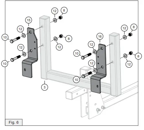
Align the Adaptor Brackets (15) and (16) to the Spreader Mount (3) as illustrated here: Add a 1/2″ Flat Washer (12) to each of four 1/2″ x 3 hex head bolts (10).
Slide these bolts through the adapter plates (15) and (16).
After each bolt passes through the plates and mount (3), secure in place using the remaining four 1/2″ flat washers (12) and 1/2″ hex nuts (8).
The ideal spreader FAN height is 22″ off the ground.
To find where the spreader mount (2) needs to be located, follow Steps 8, 9, and 10. - Measuring the Hitch Height
SPYKER
Measure from the ground to the bottom of the spreader mount (3), as illustrated below.
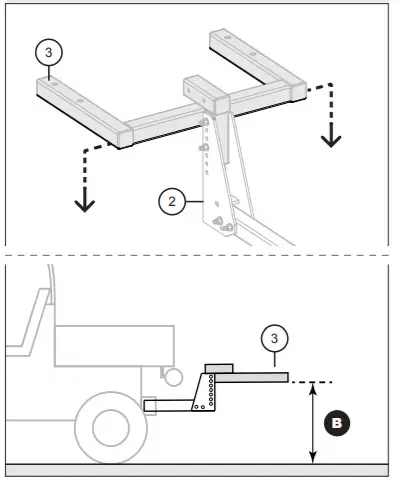
LESCO
Measure from the ground to the top of the center tubing of the spreader mount (3), as illustrated below. IF THIS MEASUREMENT IS MORE THAN 15 INCHES
The Spreader Mount (3) will need to be moved down.
Each hole in the Adjustment Plate (2) will allow for 1″ of drop. Move the Spreader Mount (3) down until dimension “B” is 15″ off the ground.
NOTE: In the Spyker configuration, the Spreader Mount (3) can be inverted 180 degrees to allow for more movement down - Mounting the Spreader
SPYKER
Align the spreader to the hitch mount (3). Add a 1/2″ flat washer (12) to each of four 1/2″ x 3″ hex head bolts (10). Slide these bolts through the spreader and hitch mount as illustrated.
After each bolt passes through, secure from below using the remaining four 1/2″ flat washers (12) and 1/2″ hex nuts (8). LESCO
LESCOAlign the spreader to the adaptor plate (16).
Add a 1/4″ flat washer (19) to two 1/4″ x 1″ hex head bolts (17). Slide these bolts through the hitch mount and spreader as illustrated.
After bolts pass through, secure each with an additional 1/4″ flat washer (19) and 1/4″ hex nut (21)
Next, add a 5/16″ washer (20) to a 5/16″ x 1″ hex bolt (18). At the base of the adaptor plate (16) run the bolt through the small gap and secure on the outside with another 5/16″ washer (20) and a 5/16″ lock nut (22).
Repeat this process on the opposite side.
- For Spyker S80-12010 Spreader, load the hopper with 120 lb ballast. For Lesco 102479 Truckster Spreader, load hopper with 80 lb ballast.
NOTE: If the FAN on the spreader is angled down toward the ground, see Steps 11 and 12 for adjustment…
…if not, skip to Step 13.
Adjusting the Spreader Angle - To adjust the spreader fan angle, all ballast must be removed.
Using the slot in the adjustment plate (3) rotate the spreader mount (2) and the adjustment plate backward. - Tighten the 3/8″ hex bolt (4) and the 3/8″ nylon lock nut that go through the slot in the adjustment plate (3) and the hole in the hitch tube (1).
NOTE: Repeat steps 10, 11, and 12 until the spreader fan is level with the ground while the hopper is filled with 120 lb of ballast. - Measure the spreader fan height to the ground with 120 lbs loaded in the hopper.
The correct spreader fan height is 22″ off the ground. If the fan is not 22″ off the ground, all the ballast must be removed, and Steps 8, 9, and 10 must be repeated until the spreader fan is 22″ from the ground. - To lock the spreader fan angle in place, loosen the nylon locknuts (6) and adjust the carriage bolt (9) down until the head of the bolt is touching the top of the hitch tube (1), then re-tighten down nylon locknuts (6).

- After locking the spreader fan angle in place from Step 14, check all bolts and nuts to be sure they are tight and secure.
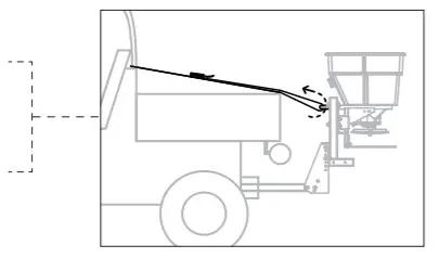
- The spreader must be secured with ratchet straps (not included) before use. Secure one end of the strap to the spreader frame and the opposite end of the strap to the UTV roll cage or bed.
 LESCO
LESCO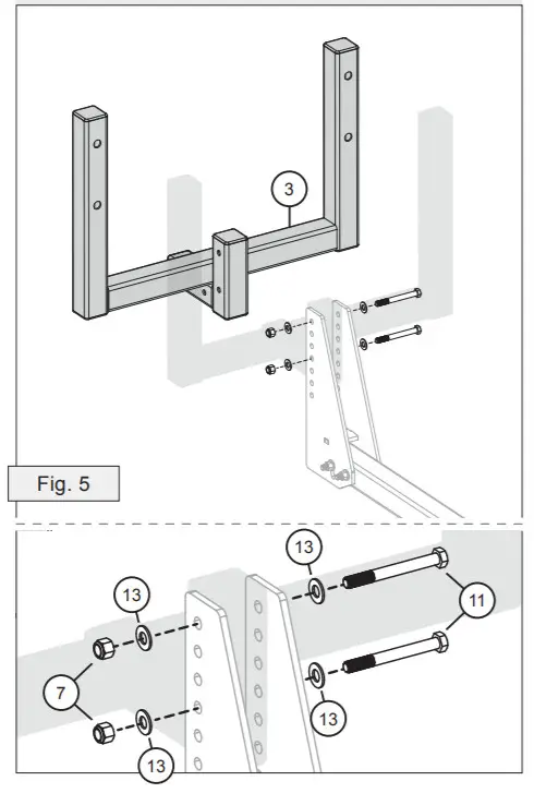
 Add a 1/2″ Flat Washer (12) to each of four 1/2″ x 3 hex head bolts (10).
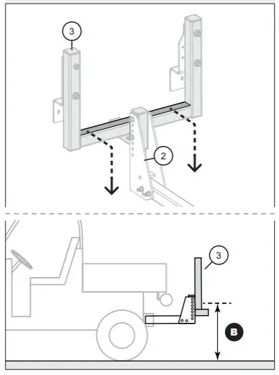
 IF THIS MEASUREMENT IS MORE THAN 15 INCHES
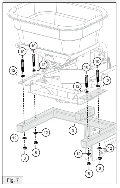 LESCO
LESCO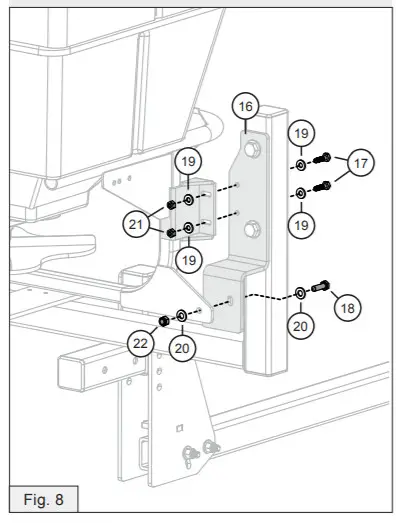
![]() DO NOT operate the spreader unless it is secured to the UTV with ratchet straps
DO NOT operate the spreader unless it is secured to the UTV with ratchet straps
WARRANTY
1 YEAR LIMITED WARRANTY
This is warranted to the original purchaser only. Spyker will replace parts with defects in materials and workmanship, for a period of one year from the date of purchase.
For Spyker Spreaders–a Brinly-Hardy Company, products employing metal gear systems, pinion, and bevel, these metal gears, only, not inclusive of any other parts or materials, are warranted for the life of the spreader, not to be used for replacement or repair past original purchase.
Spyker Spreaders will not be liable for any loss, damage or expense including, but not limited to, consequential or incidental damages, arising from the operation, condition, or use of the item. The sole and exclusive remedy against Spyker Spreaders is the replacement of the defective parts. This warranty gives you specific legal rights, and you may also have other rights which vary from state to state.
This express warranty, which is applicable only to the original purchase, is in lieu of and excludes all other warranties, whether expressed or implied by operation of law or otherwise, including any warranty of merchantability or fitness for a particular purpose.
![]()
SPYKER SPREADERS
Jeffersonville, IN 47130 USA
Phone: 800.972.6130
www.spyker.com
©2020 Spyker Spreaders/A Brinly-Hardy Co.
1019548-A


