ACCUREX XDGX Make up Air Direct Gas User Guide
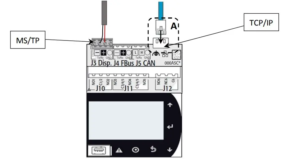
Wire Network Connection
Ethernet Port Lights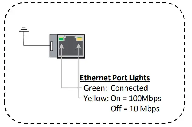
Adjust BACnet Network Settings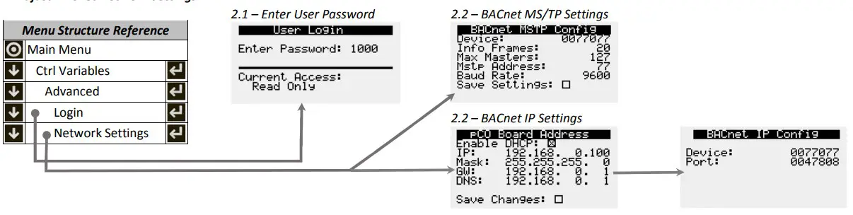
Command Unit Operation
- Enable Unit
Control Occupancy - Reset Alarms
- Global Alarm Notification
- Control Temperature Setpoint (optional)
| Object | Object Name | Object Description | Active Text | Inactive Text |
| Variable Type | ||||
| BV-2 | System_Enable | Master system enable/disable point. | Enabled | Disabled |
| BV-3 | BMS_Occupancy_Command | Occupancy Command | Unoccupied | Occupied |
| BV-4 | Reset_All_Alarms | Alarm Reset Command | Reset | Normal |
| BV-19 | Global_Alarm | Alarm Notification (any alarm by default) | Alarm | Normal |
| AV-1 | Temperature_Setpoint | Sets the active temperature set-point based on mode of operation (space setpoint, return setpoint or supplysetpoint). Not applicable for outside reset. | Default = 72°FMin = 50°F; Max = 100°F | |
Reference Guide for BACnet Integration
Please read and save these instructions for future reference. The information in this guide assumes the controller was already configured with BACnet based on the original sales configuration. If the controller does not have BACnet enabled, please contact the equipment representative to get the neces sary licensing and configuration files to allow BACnet communicationto be used.
MUA_01.001 Rev 2
Document Date: 01/2023
Basic Unit Integration
Below are the basic integration functions available on all equipment regardless of control mode. Some features are unit configuration dependent (heating type, cooling type, etc.). The controller’s BMS points list is static regardless of configuration to accommodate field configuration changes, however, not all points are applicable every unit. Once the required sensors are installed in the equipment, the only mandatory requirements to make the unit operational are to enable the unit, if it hasn’t been enabled manually at the controller, and to command occupancy as desired.
| Object | Variable | Description | Active Text | Inactive Text | ||||||
| Unit Enable/Disable Operation | ||||||||||
| If desired, the unit can be enabled and disabled by the BMS system. In disabled mode, certain safety sequences may operate to protect thebuilding and/or equipment but general heating, cooling and ventilation operation will not function. | ||||||||||
| BV-2 | System_Enable | Master system enable/disable command | Enabled | Disabled | ||||||
| Unit Occupancy Control | ||||||||||
| By default, the unit occupancy is expected to be commanded by the BMS occupancy point. Alternatively, the unit occupancy can be controlled by an internal schedule, set to always unoccupied, always occupied or controlled by a digital input by changing the occupancy mode selection at the controller. If the controller is configured for warm-up/cool-down mode, after the occupancy command is received the unit will run in unoccupied recirculation mode until reaching the occupied temperature setpoint or the warm-up/cool down time expires (default 30 minutes)at which point the controller will enter normal occupied mode operation. | ||||||||||
| BV-3 | BMS_Occupancy_Command | Building Occupancy Command | Unoccupied | Occupied | ||||||
| Alarms | ||||||||||
| The following points allow the notification of any alarm and the last alarm triggered to be read, as well as active alarms that to be manuallyreset remotely. See the unit’s full BMS points list if specific alarm monitoring or trending is desired. | ||||||||||
| BV-4 | Reset_All_Alarms | Alarm Reset Command | Reset | Normal | ||||||
| BV-19 | Global_Alarm | Global Alarm | Alarm | Normal | ||||||
| IV-9 | LatestAlm | Most recent active alarm | See Alarm Table(0 = No Active Alarm) | |||||||
| Monitoring Unit Operation | ||||||||||
| Unit status | ||||||||||
| AV-41 | Unit_Status_Mode | Unit Operation Mode/State | See Status Mode Table | |||||||
| Fans and Dampers | ||||||||||
| BI-1 | Exhaust_Fan_1_Status_Digital_Input | Exhaust Fan 1 Status | Active | Inactive | ||||||
| BI-2 | Supply_Fan_1_Status_Digital_Input | Supply Fan 1 Status | Active | Inactive | ||||||
| AV-62 | Outside_Airflow_Mask | Percentage of Outside Airflow | Real (%) | |||||||
| AV-63 | Supply_Fan_Speed_Analog_Output | Supply Fan Speed Analog Output | Real (%) | |||||||
| Cooling | ||||||||||
| IV-15*(Bit 20) | Cooling_is_On | Indicates that the unit is cooling | Active | Inactive | ||||||
| AV-43 | Cooling_1_Ramp_Capacity | Cooling Ramp 1 Status Value | Real (%) | |||||||
| Heating | ||||||||||
| IV-15*(Bit 21) | Heating_is_On | Indicates that the unit is heating | Active | Inactive | ||||||
| AV-46 | Heating_Capacity | Heating Ramp | Real (%) | |||||||
| Filters | ||||||||||
| IV-13*(Bit 3) | Filter_Alarm_Digital_Input | Filter Alarm Digital Input Status | Alarm | Normal | ||||||
| Refrigeration Systems | ||||||||||
| IV-10*(Bit 3) | Compressor_1_Enable_Digital_Output | Compressor 1 Enable Digital Output | Active | Inactive | ||||||
| IV-10*(Bit 4) | Compressor_2_Enable_Digital_Output | Compressor 2 Enable Digital Output | Active | Inactive | ||||||
| AV-64 | Modulating_Compressor_Analog_Output_BMS | Modulating Compressor Analog Output | Real (%) | |||||||
| Object | Variable | Description | Active Text | Inactive Text | ||||||
| Chilled Water Systems | ||||||||||
| AV-58 | Chilled_Water_1_Valve_Analog_Output | Chilled Water 1 Valve Analog Output | Real (%) | |||||||
| Evaporative Cooling Systems | ||||||||||
| IV-10*(Bit 16) | Evap_Valve_Enable_Digit_Output | Evaporative Cooling Valve Enable | Active | Inactive | ||||||
| IV-10*(Bit 17) | Evap_Pump_Enable_Digit_Output | Evaporative Cooling Pump Enable | Active | Inactive | ||||||
| Hot Water Systems | ||||||||||
| AV-60 | Hot_Water_Valve_1_Analog_Output | Hot Water Valve 1 Analog Output | Real (%) | |||||||
| IG Furnaces | ||||||||||
| IV-10*(Bit 7) | Furnace_1_Stage_1_Digital_Output | Furnace 1 Stage 1 Digital Output | Active | Inactive | ||||||
| IV-10*(Bit 8) | Furnace_1_Stage_2_Digital_Output | Furnace 1 Stage 2 Digital Output | Active | Inactive | ||||||
| IV-10*(Bit 9) | Furnace_2_Stage_1_Digital_Output | Furnace 2 Stage 1 Digital Output | Active | Inactive | ||||||
| IV-10*(Bit 10) | Furnace_2_Stage_2_Digital_Output | Furnace 2 Stage 2 Digital Output | Active | Inactive | ||||||
| IV-10* (Bit 11) | Furnace_3_Stage_1_Digital_Output | Furnace 3 Stage 1 Digital Output | Active | Inactive | ||||||
| AV-61 | Mod_Gas_Furnace_1_Analog_Output | Mod Gas Furnace 1 Analog Output | Real (%) | |||||||
| Electric Post-Heat | ||||||||||
| IV-10* (Bit 15) | Electric_Heater_Start_Stop_Digital_Output | Electric Heater Digital Output | ||||||||
| AV-59 | Electric_Heater_1_Analog_Output | Electric Heater 1 Analog Output | Real (%) | |||||||
| Direct Gas Burner | ||||||||||
| IV-10* (Bit 14) | Direct_Gas_Heating_Enable_Digital_Output | Direct Gas Enable Digital Output | Active | Inactive | ||||||
| Sensor Values (when equipped) | ||||||||||
| AI-1 | Space_Temp_Analog_Input | Space Air Temperature | Real (°F) | |||||||
| AI-2 | Supply_Temp_Analog_Input | Supply(discharge) Air Temperature | Real (°F) | |||||||
| AI-3 | Outside_Air_Temp_Analog_Input | Outside Air Temperature | Real (°F) | |||||||
| AI-9 | Space_Static_Pressure_Analog_Input | Space Static Pressure | Real (“wc) | |||||||
| AI-10 | Supply_Duct_Static_Pressure_Analog_Input | Supply Duct Static Pressure | Real (“wc) | |||||||
| AI-11 | Space_CO2_1_Analog_Input | Space 1 CO2 ppm | Real (ppm) | |||||||
| AI-12 | Return_CO2_Analog_Input | Return CO2 ppm | Real (ppm) | |||||||
| AV-56 | OAD_CFM_BMS | Outdoor Air Damper CFM | Real (cfm) | |||||||
| Active Setpoints | ||||||||||
| AV-42 | Supply_Temperature_Calculated_Setpoint | Active Supply Temperature Setpoint | Real (°F) | |||||||
Unpacking Integer Words to Binary Values
Binary values can be combined to create an integer word. By doing this, more information is available to the BMS in a smaller number of points and less network traffic. These integer words need to be “unpacked” once the BMS receives the value.
| Object Variable Description Reference Table | |||
| Packed Integer Words | |||
| IV-10 | Digital_Output_Word | Digital Output Enables | Bit Packed Word – See Binary Tables |
| IV-11 | Cooling_Alarm_Word | Cooling Device Alarms | Bit Packed Word – See Binary Tables |
| IV-12 | Device_Offline_Word | Device Communication Alarms | Bit Packed Word – See Binary Tables |
| IV-13 | Device_Alarm_Word | Device Alarms | Bit Packed Word – See Binary Tables |
| IV-14 | Heating_Alarm_Word | Heating Device Alarms | Bit Packed Word – See Binary Tables |
| IV-15 | Unit_Status_Word | Unit Status Word | Bit Packed Word – See Binary Tables |
To unpack the integer word into the binary values, the integer needs to be converted to a binary number. The integers in the program are 32-bit, meaning up to 32 binary values are packed into the integer. Each bit can either be a 0 (Inactive) or a 1 (Active).
The BMS front end may have a solution already intact to pull individual bits from an integer. A “read bit” function looks to return what value a certain bit is in an integer. Bit number are 0-31 in a 32-bit integer with 0 being the lowest bit and the furthest to the right in the binary notation of the number. Bit 31 would be the largest bit and the furthest to the left in binary notation.
If the front end does not have a “read bit” or “bit extract” function, the binary value of individual bits can be determined by continually dividing the quotient of the integer by 2, the remainder of the division is the value of the bit (0 or 1). A function called Modulo or “mod” and is commonly used to return the remainder of integer division.
Equation: x = (round down(a/2b ) )mod 2
- x is Boolean value for bit b, where 0 is inactive and 1 is active.
- a is the integer word value
- b is the bit of the binary number used as an exponent
- The result of a/2b should round down to a whole number, truncating the decimal. For example, 5/21 is 2.5, however, only the 2 is used.
Example:
If the Device_Offline_Word (IV-12) is a decimal value of 11, the binary value would be 1011. This binary value would mean that Space Thermostats 1, 2, and 4 are offline. The rest of the bits in the binary number would be a Boolean value of 0. (Please see Binary Tables.)
- Bit 0 = 11/20 mod 2… this results in a Boolean of 1 or Active for bit 0.
- Bit 1 = 11/21 mod 2… this results in a Boolean of 1 or Active for bit 1.
- Bit 2 = 11/22 mod 2… this results in a Boolean of 0 or Inactive for bit 2.
- Bit 3 = 11/23 mod 2… this results in a Boolean of 1 or Active for bit 3.
| Bit | 31 | 30 | 29 | 28 | 27 | 26 | 25 | 24 | 23 | 22 | 21 | 20 | 19 | 18 | 17 | 16 | 15 | 14 | 13 | 12 | 11 | 10 | 9 | 8 | 7 | 6 | 5 | 4 | 3 | 2 | 1 | 0 |
| Val | 0 | 0 | 0 | 0 | 0 | 0 | 0 | 0 | 0 | 0 | 0 | 0 | 0 | 0 | 0 | 0 | 0 | 0 | 0 | 0 | 0 | 0 | 0 | 0 | 0 | 0 | 0 | 0 | 1 | 0 | 1 | 1 |
Modifying Equipment Operation
In addition to commanding unit occupancy, some system level sequences may require feedback from the BMS. Common BMS adjusted sequences include items like supply air temperature reset control, demand control ventilation for multiple zones, and duct static pressure reset.
HEATING AND COOLING OPERATION SETPOINTS
| Object | Variable | Description | Active Text | Inactive Text | ||
| Adjusting Temperature Setpoints | ||||||
| Controller Provided Sequences – Occupied Mode | ||||||
| The controller has several stand-alone supply air temperature control modes with setpoints that can be modified by the BMS. These modes include a static supply air temperature setpoint (no-reset) or allows for the supply air temperature setpoint to be reset based on outside air temperature, spacetemperature, or return air temperature. | ||||||
| IV-1 | Temperature_Reset_Mode | Commands the reset mode during occupiedoperation. | 1 = No Reset, 2 = Space Reset3 = Return Reset, 4 = Outside Reset | |||
| AV-1 | Temperature_Setpoint | Sets the temperature setpoint based on mode of operation (space setpoint, return setpoint or supply setpoint).Not applicable for outside reset. | Real, Default = 72°F*Min = 50°F; Max = 120°F | |||
| AV-2 | Temperature_Heat_Cool_Deadband | Heat/Cool Setpt Deadband when Space or Return reset control is active.Htg Setpt = Temp Setpt – Deadband /2 Clg Setpt = Temp Setpt – Deadband /2 | Real, Default = 4°F Min = 0.1°F; Max = 20°F[Space/Return Heating = 70°F, Space/Return Cooling = 74°F] | |||
| Controller Provided Sequences – Unoccupied Mode | ||||||
| When the unoccupied mode of operation is set to night setback temperature, normal operation with unoccupied setpoints, or recirculation withunoccupied setpoints, the following setpoints control unoccupied heating and cooling operation. If night setback is selected as the Unoccupied Mode of operation, the reset mode will not be available to change at the controller and should be set to Space Reset(2). | ||||||
| IV-2 | Temperature_Reset_Mode_Unoccupied | Commands the reset mode during occupiedoperation. | 1 = No Reset, 2 = Space Reset3 = Return Reset, 4 = Outside Reset | |||
| AV-3 | Temperature_Setpoint_Unoccupied | Sets the temperature setpoint based on mode of operation (space setpoint, return setpoint or supply setpoint).Not applicable for outside reset. | Real, Default = 72.5°F*Min = 50°F; Max = 120°F | |||
| Object | Variable | Description | Active Text Inactive Text | |||
| AV-4 | Temperature_Heat_Cool_Deadband_Unoccupied | Heat/Cool Setpt Deadband when Space or Return reset control is active.Unooc Clg Setpt = Deadband /2 + Temp Setpt Unocc Htg Setpt = Deadband /2 – Temp Setpt | Real, Default = 15°F Min = 0.1°F; Max = 40°F[Space/Return Heating = 65°F, Space/Return Cooling = 80°F] | |||
| BMS Controlled Sequences | ||||||
| BMS control over reset write to temp setpoint and have mode in No reset. | ||||||
AIRFLOW OPERATION SETPOINTS
| Object | Variable | Description | Active Text | Inactive Text |
| Airflow Setpoints | ||||
| Airflow operation of supply fan, exhaust fan, and mixing dampers may use setpoints from duct pressure, space pressure, CO2 sensors, or airflow measuring stations to properly control airflow in an application. The Outside Air Damper Minimum Setpoint Occupied applies to all units withmodulating outside air dampers. The setpoint is used to establish an absolute minimum position for ventilating the space while allowing other control modes to open the damper further as necessary. Outdoor and recirculating air dampers operate inversely using the same signal. | ||||
| AV-16 | Space_Static_Pressure_Setpoint | Space Static Pressure Setpoint | Default = 0.05”wcMin = -0.5”wc; Max = 0.5”wc | |
| AV-17 | Supply_Duct_Static_Pressure_Setpoint | Supply Duct Static Pressure Setpoint | Default = 1.0”wcMin = 0”wc; Max = 5”wc | |
| AV-18 | Space_CO2_Setpoint | Space CO2 Setpoint | Default = 1,000 ppmMin = 0 ppm; Max = 5,000 ppm | |
| AV-19 | Outside_Air_Damper_Minimum_Setpoint_Occ | Outside Air Damper Minimum Setpoint Occupied | Default = 35%Min = 0%; Max = 100% | |
BMS Watchdog Enabled Control
BMS WATCHDOG
When directly commanding fans speeds, damper positions, or sending sensor values, the unit controller requires the BMS Watchdog point to be written to on a recurring basis. This tells the unit controller that the BMS is still actively communicating.
| Object | Variable | Description | Active Text | Inactive Text |
| BMS Watchdog | ||||
| The BMS Watchdog must be written to True (1) regularly to verify communication is established between the unit controller and the BMS headend system. If the BMS Watchdog value remains False(0) for longer than the Timeout Delay (15 minutes, adjustable), an alarm is generated and thecontroller falls back to local control and sensor values, as applicable, instead of using BMS commanded values. | ||||
| BV-1 | BMS_Watchdog | BMS Watchdog command | Active | Inactive |
| BV-20 | BMS_Watchdog_Active | Status of the BMS watchdog ping. | Active | Inactive |
CONTROLLING AIRFLOW DEVICES
If desired, the speeds and positions of airflow devices can be controlled directly using BACnet commandable points. To control the devices via the BMS, the BMS Watchdog requirements must be satisfi.
| Object | Variable | Description | Active Text | Inactive Text | |
| Fan Controls | |||||
| Fan speeds can be controlled directly though BMS points. The binary points enable the BMS to take control and the analog values command thespeeds as a percentage between the allowed minimum and maximum values set in the controller. | |||||
| Supply Fan | |||||
| BV-14 | SF_Control_Source_BMS | Allows the BMS to control supply fan speed | BMS | Local | |
| AV-38 | SF_Control_Signal_BMS | Supply Fan Command Speed | Real (%)*Min=50%; Max=100% | ||
| Outdoor Air/Recirculation Air Damper Control | |||||
| The outdoor air damper position can be controlled directly by the BMS to adjust the mixture of outdoor air and recirculation air on units configured forrecirculation. Minimum and maximum values for occupied and unoccupied mode set at the unit controller are enforced. | |||||
| BV-15 | OAD_Control_Source_BMS | Allows the BMS to control OAD position | BMS | Local | |
| AV-39 | OAD_Control_Signal_BMS | Outside Air Damper Control Signal via BMS | Real (%)Min=0%; Max=100% | ||
SENDING SENSOR VALUES
Sensor values required for sequence operation can be sent to the controller over dedicated BMS points in place of a sensor wired to the controller (local sensor). When values are communicated to the controller over BMS, the BMS Watchdog must be satisfied. If the watchdog isn’t satisfied, the controller reverts to the local sensor (if installed and valid) to control the unit or falls back to local control until the BMS watchdog is satisfied.
| Object | Variable | Description | Active Text | Inactive Text |
| BMS Writeable Sensor Values | ||||
| To write the sensor values over BMS, first command the controller to use the BMS value using the corresponding binary value and then use thecorresponding analog value to send the sensor value. | ||||
| Sensor Sources | ||||
| BV-6 | Outside_Temp_Source_BMS | Outside Temp Source Selection | BMS | Local |
| BV-9 | Space_1_CO2_Source_BMS | Space 1 CO2 Source Selection | BMS | Local |
| BV-10 | Return_CO2_Source_BMS | Return CO2 Source Selection | BMS | Local |
| BV-12 | Space_Static_Source_BMS | Space Static Source Selection | BMS | Local |
| BV-13 | Space_Temp_Source_BMS | Space Temp Source Selection | BMS | Local |
| Sensor Values | ||||
| AV-30 | Outside_Temp_from_BMS | Outside Temp from BMS | Real (°F) | |
| AV-33 | Space_1_CO2_from_BMS | Space 1 CO2 from BMS | Real (ppm) | |
| AV-34 | Return_CO2_from_BMS | Return CO2 from BMS | Real (ppm) | |
| AV-36 | Space_Static_from_BMS | Space Static from BMS | Real (“wc) | |
| AV-37 | Space_Temp_from_BMS | Space Temp from BMS | Real (°F) | |
Advanced BACnet Settings
Additional settings can be accessed in the BACnet Advanced Settings menu includingBACnet Broadcast Management Device (BBMD) configuration, relinquish default settings, Change of Value (COV) increments and restoring binary text value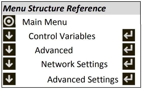
BBMD CONFIGURATION
To configure the controller to operate with a BACnet Broadcast Management Device (BBMD) on IP networks, go to the advanced BACnet settings menu and enter the IP
address of the BBMD, foreign device configuration, and time to live setting.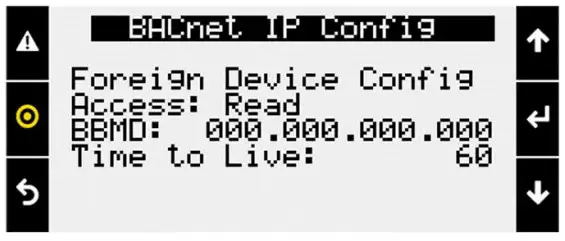
COV INCREMENTS
BACnet COV is an optional portion of BACnet that supports providing new
values/information only after an increase or decrease of the value is at least the listed
COV increment. The controller’s COV increments are based on the unit of measure. All variables with the same unit of measure share the same COV increment value. Valuescan be adjusted on this screen, or by writing to the COV increment property of any BACnet object.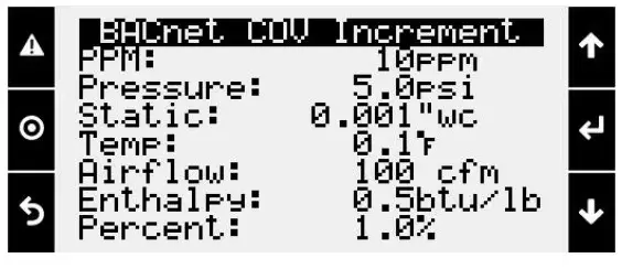
RELINQUISH DEFAULT SETTINGS
When the Return to Default function is enabled, the present value will not overwrite
the relinquish default value and on a loss of power the controller will boot with last
saved default values instead of last written values. This must also be enabled for the BACnet Comm Loss relinquish default to work.
When the Enable Relinquish Default function is enabled any value in the priority array
for binary values or analog values will be cleared if a communication loss is detected. All commandable points will revert to the relinquish default value.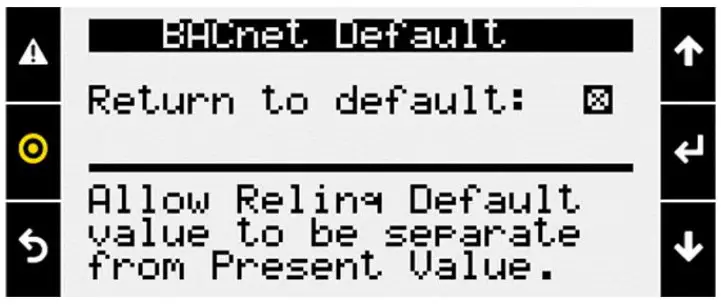
Communication loss is determined based on the BMS Watchdog. The watchdog function must be enabled. The function will execute 5 minutes after the watchdog status goes inactiv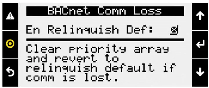
This may be desired if the BMS is running a reset routine on the setpoints and would
like to revert to a default state if communication is lost. It is recommended to be used
with return to default enabled, and a known relinquish default is saved. When this box is checked by a user, the controller will write the present value of variables to the relinquish default for all binary and analog value BACnet objects that are commandable. The function operates in the background and takes approximately30 seconds to complete.
This is desired to save any Test and Balance settings adjusted locally on the controller to be the BACnet relinquish default values. Alternatively, these values could be read and written to the relinquish default variables by the BMS system.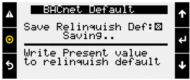
BINARY TEXT
If for any reason, the state text is missing from binary objects, checking this box will cause the controller to re-write the active and inactive text values.
MUA Reference Table
STATUS MODE TABLE
The following analog values can appear in the point to tell the building automation the current mode of operation of the unit. Values may rotate every three seconds.
| Status Mode Table (AV-41) | |||||
| Analog Value | Mode | Analog Value | Mode | Analog Value | Mode |
| 0 | Off/Standby | 10 | System On | 21 | Cooling |
| 1 | Unoccupied Start | 11 | Soft Shutdown | 22 | Heating |
| 2 | Occupied Start | 12 | System Disabled | 30 | Overrides |
| 3 | Opening Dampers | 13 | Remote Off | 31 | Expansion Offline |
| 5 | Dampers Open | 14 | System Shutdown Alarm | 32 | Occupancy Overridden |
| 6 | Fan Start Delay | 18 | Unit Off Flow Active | 33 | Max Vent Sequence Active |
| 7 | Exhaust Fan Start | 19 | Fans Only | 35 | Morning Sequence Active |
| 8 | Supply Fan Start | 20 | Economizing | 36 | Winter Ramp Active |
| 9 | Startup Delay | ||||
ALARM TABLE
This table displays the latest alarm that is active in the unit controller.
| Alarm Table – Latest Alarm (IV-9) | |||
| 0 | No Active Alarms | 27 | IG Furnace 1 Combust Fan High Pressure Switch |
| 1 | Supply Fan Run Status Not Proven | 28 | IG Furnace 1 Ignition Controller Alarm |
| 2 | Exhaust Fan Run Status Not Proven | 29 | IG Furnace 1 Pressure Switch Fault Alarm |
| 3 | Filters are Dirty Replace Filters | 30 | IG Furnace 1 Combust Fan Proving Alarm |
| 4 | Cond Drain Pan Full Check Drain | 31 | IG Furnace 1 Max Retries |
| 5 | High Supply Duct Static Pressure | 32 | IG Furnace 1 High Limit Trip |
| 6 | Outside Air Temp Sensor Value Not Valid | 33 | IG Furnace pCOe 1 Offline |
| 7 | Space Temperature Sensor Value Not Valid | 34 | IG Furnace 1 IC Fault Check IC->pCOe Wiring |
| 8 | Supply Air Temperature Sensor Value Not Valid | 35 | IG Furnace 1 Combustion Fan Alarm |
| 9 | Outside Air GreenTrol Offline or Flow Error | 36 | IG Furnace pCOe 2 Offline |
| 10 | Hi/Low Pressure Switch Circuit A | 37 | IG Furnace 2-No Flame Alarm After 3 Tries |
| 11 | Hi/Low Pressure Switch Circuit B | 38 | IG Furnace 2 Max Retries |
| 12 | Space CO2 Sensor Value Not Valid | 39 | IG Furnace 2 Ignition Controller Alarm |
| 13 | Return CO2 Sensor Value Not Valid | 40 | IG Furnace 3-No Flame Alarm After 3 Tries |
| 14 | Space Static Pressure Sensor Value Not Valid | 41 | IG Furnace 3 Max Retries |
| 15 | Supply Duct Stat Press Sensor Value Not Valid | 42 | IG Furnace 3 Ignition Controller Alarm |
| 16 | Supply Air Temperature Low Limit Shutdown | 43 | DG Flame Safeguard General Reference |
| 17 | Supply Air Temperature High Limit Shutdown | 44 | DG Flame Safeguard Manual Reset at FSG |
| 18 | Space High Static Pres Shutdown | 45 | DG Pilot Flame Alarm Did Not Prove |
| 19 | BMS Offline Watchdog is FALSE | 46 | DG Heating Safety Check Circuit |
| 20 | BACnet License Not Installed | 47 | DG Flame Safeguard Check Functionality |
| 21 | Space Thermostat 1 Sensor Offline | 48 | DG Burner Differential Check Pressure |
| 22 | Space Thermostat 2 Sensor Offline | 51 | Multi Devices per Ch Contact Tech Support |
| 23 | Space Thermostat 3 Sensor Offline | 52 | Comp Maintenance Alarm Run Hours Setpoint Reached |
| 24 | Space Thermostat 4 Sensor Offline | 54 | Non-Volatile Memory Er Contact Tech Support |
| 25 | IG Furnace 1-No Flame Alarm After 3 Tries | 55 | Cooling Exp Board pCOe 3 Offline |
| 26 | IG Furnace 1 – Large No Flame After 3 Tries | 59 | Exp Board 4 Status Board is Offline |
BIT-PACKED INTEGER WORD TABLES
The following tables are used to unpack integer words into Boolean values.
| Digital Output Table (IV-10) | |||||
| Bit | Digital_Output_Word | Bit | Digital_Output_Word | Bit | Digital_Output_Word |
| 0 | Supply Fan Start | 11 | Furnace 3 Start | 22 | |
| 1 | Exhaust Fan Start | 12 | 23 | ||
| 2 | Exhaust Relief Enable | 13 | Damper Actuator Power Enable | 24 | |
| 3 | Compressor 1 Start | 14 | Direct Gas Start | 25 | |
| 4 | Compressor 2 Start | 15 | Electric Heat Start | 26 | |
| 5 | Condenser Fan Start | 16 | Evaporative Cooling Valve Enable | 27 | |
| 6 | 17 | Evaporative Cooling Pump Enable | 28 | ||
| 7 | Furnace 1 Start | 18 | 29 | ||
| 8 | Furnace 1 Stage 2 Start | 19 | 30 | ||
| 9 | Furnace 2 Start | 20 | 31 | ||
| 10 | Furnace 2 Stage 2 Start | 21 | |||
| Cooling Alarm Table (IV-11) | |||||
| Bit | Cooling_Alarm_Word | Bit | Cooling_Alarm_Word | Bit | Cooling_Alarm_Word |
| 0 | Circuit A High/Low Pressure Switch Alarm | 11 | 22 | ||
| 1 | Circuit B High/Low Pressure Switch Alarm | 12 | 23 | ||
| 2 | 13 | 24 | |||
| 3 | 14 | 25 | |||
| 4 | 15 | 26 | |||
| 5 | 16 | 27 | |||
| 6 | 17 | 28 | |||
| 7 | 18 | 29 | |||
| 8 | 19 | 30 | |||
| 9 | 20 | 31 | |||
| 10 | 21 | ||||
| Device Offline Table (IV-12) | |||||
| Bit | Device_Offline_Word | Bit | Device_Offline_Word | Bit | Device_Offline_Word |
| 0 | Space T-Stat 1 Offline | 11 | 22 | ||
| 1 | Space T-Stat 2 Offline | 12 | 23 | ||
| 2 | Space T-Stat 3 Offline | 13 | 24 | ||
| 3 | Space T-Stat 4 Offline | 14 | 25 | ||
| 4 | IG Furnace Controller 1 Offline | 15 | 26 | ||
| 5 | IG Furnace Controller 2 Offline | 16 | 27 | ||
| 6 | Cooling Controller Offline | 17 | 28 | ||
| 7 | GreenTrol Outside Air Offline | 18 | 29 | ||
| 8 | BMS Offline Alarm | 19 | 30 | ||
| 9 | Permanent Memory – Too Many Writes | 20 | 31 | ||
| 10 | 21 | ||||
| Device Alarms Table (IV-13) | |||||
| Bit | Device_Alarm_Word | Bit | Device_Alarm_Word | Bit | Device_Alarm_Word |
| 0 | Supply Fan Alarm | 11 | Supply High Duct Static Alarm | 22 | |
| 1 | Exhaust Fan Alarm | 12 | Supply Duct Static Sensor Alarm | 23 | |
| 2 | Drain Pan Alarm | 13 | Space Static Pressure Sensor Alarm | 24 | |
| 3 | Filter Alarm | 14 | Space High Static Alarm | 25 | |
| 4 | GreenTrol OAD AFMS Alarm | 15 | Return CO2 Sensor Alarm | 26 | |
| 5 | Outside Air Temp Sensor Alarm | 16 | 27 | ||
| 6 | Space CO2 Sensor Alarm | 17 | Shutdown Input Alarm | 28 | |
| 7 | Supply Air Temp Sensor Alarm | 18 | 29 | ||
| 8 | Space Temperature Sensor Alarm | 19 | 30 | ||
| 9 | Supply Temp Low Limit Alarm | 20 | 31 | ||
| 10 | Supply Temp High Limit Alarm | 21 | |||
| Heating Alarm Table (IV-14) | |||||
| Bit | Heating_Alarm_Word | Bit | Heating_Alarm_Word | Bit | Heating_Alarm_Word |
| 0 | DG Flame Safeguard General Reference | 11 | IG Furnace 1 Pressure Switch Fault Alarm | 22 | IG Furnace 3 Ignition Controller Alarm |
| 1 | DG Flame Safeguard Manual Reset at FSG | 12 | IG Furnace 1 Combust Fan Proving Alarm | 23 | |
| 2 | DG Pilot Flame Alarm Did Not Prove | 13 | IG Furnace 1 Max Retries | 24 | |
| 3 | DG Heating Safety Check Circuit | 14 | IG Furnace 1 High Limit Trip | 25 | |
| 4 | DG Flame Safeguard Check Functionality | 15 | IG Furnace 1 IC fault Check Furnace Wiring | 26 | |
| 5 | DG Burner Differential Check Pressure | 16 | IG Furnace 1 Combustion Fan Alarm | 27 | |
| 6 | General IG Furnace Alarm | 17 | IG Furnace 2-No Flame Alarm After 3 Tries | 28 | |
| 7 | IG Furnace 1 No flame Alarm After 3 Tries | 18 | IG Furnace 2 Max Retries | 29 | |
| 8 | IG Furnace 1 Large No Flame After 3 Tries | 19 | IG Furnace 2 Ignition Controller Alarm | 30 | |
| 9 | IG Furnace 1 Combust Fan High PressureSwitch | 20 | IG Furnace 3-No Flame Alarm After 3 Tries | 31 | |
| 10 | IG Furnace 1 Ignition Controller Alarm | 21 | IG Furnace 3 Max Retries | ||
| Unit Status Word Table (IV-11) | |||||
| Bit | Unit_Status_Word | Bit | Unit_Status_Word | Bit | Unit_Status_Word |
| 0 | Off/Standby | 11 | Remote Off | 22 | Dehumidifying |
| 1 | Unoccupied Start | 12 | System Shutdown Alarm | 23 | Hot Gas Reheat Active |
| 2 | Occupied Start | 13 | Supply Fan Only | 24 | HGRH Purging |
| 3 | Opening Dampers | 14 | Exhaust Fan Only | 25 | Dehum w/Heat |
| 4 | Dampers Open | 15 | Purge Mode (Supply and Exhaust Only) | 26 | Energy Recovery Defrost Active |
| 5 | Fan Start Delay | 16 | Case Heat Active | 27 | Heat Pump Defrost Active |
| 6 | Exhaust Fan On | 17 | Fans Only | 28 | Morning Warm Up/Cool Down Active |
| 7 | Supply Fan On | 18 | Economizing | 29 | Winter Ramp Active |
| 8 | System On | 19 | Energy Recovery Active | 30 | |
| 9 | Soft Shutdown | 20 | Cooling | 31 | Overrides Active |
| 10 | System Disabled | 21 | Heating | ||


