
![]()

INSTRUCTION
MANUAL![]()

| This is not a toy! Not suitable for children under 14 years old without adult supervision. |  |
DECLARATION OF CONFORMITY IN ACCORDANCE WITH THE (RED) 2014/53/EU DIRECTIVE
Sarl Imodel 3 rue Labouche 31100 Toulouse France![]() This product must not be disposed of with other waste. Instead, it is the user’s responsibility to dispose of their waste equipment by handing it over to a designated collection point for the recycling of waste electrical and electronic equipment. Help us to protect the environment and respect our resources!
This product must not be disposed of with other waste. Instead, it is the user’s responsibility to dispose of their waste equipment by handing it over to a designated collection point for the recycling of waste electrical and electronic equipment. Help us to protect the environment and respect our resources!
Declares that the following product: KONECT KT3X Transmitter & KR3X Receiver Item Number: KN-KT3X/SET
Complies with the essential requirements and other relevant provisions of the European directive (RED) 2014/53/EU:
ETSI EN 301 489-1 V2.2.3 (2019-11)
Electromagnetic Compatibility and radio spectrum matters (ERM) ; Electromagnetic Compatibility (EMC) for radio equipment and services;
Part 1: Common technical requirements
ETSI EN 301 489-1 V2.2.3
Electromagnetic Compatibility (EMC) standard for radio equipment and services; Part 1: Common technical requirements; Harmonised Standard covering the essential requirements of article 3.1(b) of Directive 2014/53/EU and the essential requirements of article 6 of Directive 2014/30/EU
ETSI EN 301 489-17 V3.2.4
Electromagnetic Compatibility (EMC) standard for radio equipment and services; Part 17: Specific conditions for Broadband Data Transmission Systems; Harmonised Standard covering the essential requirements of article 3.1(b) of Directive 2014/53/EU
ETSI EN 300 328 V2.2.2:2019
Wideband transmission systems; Data transmission equipment operating in the 2,4 GHz ISM band and using wide band modulation techniques; Harmonised Standard for access to radio spectrum
EN 62479:2010
Assessment of the compliance of low power electronic and electrical equipment with the basic restrictions related to human exposure to electromagnetic fields (10 MHz to 300 GHz) i.A
Manufacturer Address: Sarl Imodel – 3 rue Labouche – 31100 Toulouse – France
Date of issue: 27 September 2021![]() the reproduction even partial of this manual is forbidden – No contractual illustrations – Specifications are subject to change without notice – No liability for printing errors and mistakes.
the reproduction even partial of this manual is forbidden – No contractual illustrations – Specifications are subject to change without notice – No liability for printing errors and mistakes.
90 DAYS WARRANTY AND SERVICE INFORMATION
COMPONENT WARRANTY PERIOD
PLEASE READ THE FOLLOWING INFORMATION CAREFULLY!
Please note this is a high-quality hobby product and not a toy. Therefore, it is necessary that children under 14 years are supervised by an adult. The guardians and/or parents have the responsibility to provide the appropriate guidance and supervision of the minors.
A remote control car can withstand many shocks during use, but some can cause parts to break. Unsuitable driving and terrain can also cause mechanical breakage (transmission gears, servo pinions, etc.). These breakages are not guaranteed. We advise you to train yourself to pilot your vehicle in an open space and at low speed. The duration of this training can vary according to the dexterity of each pilot.
NOTE: In cold weather, the risk of plastic parts breaking is higher This product has a 90-day warranty, which is only guaranteed to the original purchaser. The warranty is valid only to products that have been purchased from an authorized Hobbytech dealer. Warranty claims will be processed only with valid proof of purchase/receipts. If within the warranty period, a portion of the product fails due to manufacturing defects, then it is within the discretion of Hobbytech to repair it or replace it. The decision to repair or replace the part will be taken by Hobbytech. After use, we do not offer new for old warranty.
WARRANTY DISCLAIMER
This high-performance model was made with the highest attention and care and should be treated with respect. Excluded from the warranty are components that have been damaged by wrong installation, mishandling, accident, operation, maintenance, lack of maintenance and care, as well as abuse and/or repair attempts. Furthermore excluded from the guarantee are wearing parts such as fuses and batteries, visual impairments, shipping -, and transport costs.
WARRANTY CLAIM
Please contact your dealer with the warranty claim and/or repair. Your dealer and Hobbytech will make a proper decision that will help you as soon as possible. For invalid warranty claims, you may be charged for the processing costs before the parts are returned. All repairs which are necessary by negligence or abuse are bill in advance. In case you decide that you not want to repair your product then Hobbytech editing and reserves the right to charge shipping costs.
IMPORTANT – READ THIS BEFORE RUNNING
CAUTION
To avoid serious personal injury and property damage, operate all remotely controlled models in a responsive manner as outlined below.
R/C car models can exceed speeds of 40km/h (25mph), and cannot be stopped quickly.
- Never run R/C models on the street or highways, as it could cause or contribute to serious traffic accidents.
- Never run an R/C model near people or animals, nor use people or animals as obstacles when operation R/C vehicles.
- It is advisable to use screwdrivers dedicated to Rc hobby to avoid damaging your screw heads.
- Running R/C models into furniture or other inanimate objects will cause damage to the objects and the R/C models.
CAUTION DURING OPERATIONS
When the R/C model is in operation, dot not touch any of its moving parts, such as drive shafts, and wheels, as the rotating parts can cause serious injury.
- The vehicle motor gets very hot during running and could cause burns if touched.
- Make sure that no one else is using the same frequency as yours in your running area. Using the same frequency at the same time, whether is driving, flying or sailing, can cause a loss of control of the R/C models, resulting in serious accidents.
- Properly connect plugs. To prevent electrical shock and/or damage to the product resulting from a short-circuit; insulate connections with heat shrink tubing or electrical tape. Before running the vehicle, check that battery wiring and plugs are not so loose as to drag on the ground. Properly secure cables using electrical tape or nylon tie-wraps.
- Stiff rotation of gears, shafts, joints and wheels can burn out the motor. It’s recommended to check proper joint and shaft rotation by using one 1,5V dry cell during the assembly of the model. A worn motor will overheat and result in a short running time. Replace a worn-out motor as soon as possible.
- R/C models will run out of control when either the receiver or the transmitter battery voltage drops off. Stop the vehicle immediately when the car starts to slow down to prevent it from running out of control.
SAFETY PRECAUTIONS
Follow the outlined rules for safe radio control operation.
Avoid running the car in a crowded area and near small children.
Make sure that no one else is using the same frequency in your running area. Using the same frequency at the same time can cause serious accidents, whether it’s driving, flying or sailing.
Avoid running in standing water and rain. If the R/C unit, motor, or battery gets wet, clean and dry thoroughly in a dry shaded area.
R/C operating procedures
- Make sure the transmitter controls and trims are in neutral. Switch on the transmitter.
- Switch on the receiver.
- Inspect operation using transmitter before running.
- Adjust steering servo and trim so that the model runs straigHT-with transmitter in neutral.
- Reverse sequence to shut down after running.
- Make sure to disconnect/remove all batteries.
- After each use, it is necessary to clean your car, to check its general condition, and to check the tightness of the screws. If you have been driving on sandy ground, it is necessary to clean your car after each use and to check the condition of the main gear and motor pinion. If you drive in wet weather, it is necessary to dry your vehicle and apply lubricant (Lub In type) to the visible mechanical parts and other metal parts.
- Store the car and batteries separately when not in use.
If you have any doubts or problems, please do not hesitate to contact your dealer. Resellers are specialists who can bring you all their experience to help you make the most of this hobby.
For obvious reasons of security, the KONECT KT3X radio system is equipped with an automatic power shut down of the receiver when the user turns the transmitter On while turning the steering wheel or touching the throttle trigger. Consequently, on the ignition, the vehicle won’t (for example) unintentionally accelerate. The transmitter Led flashes red & green, and the user cannot use it anymore. Then it must be turned Off and On without touching anything else.
Functions
KT3X Transmitter
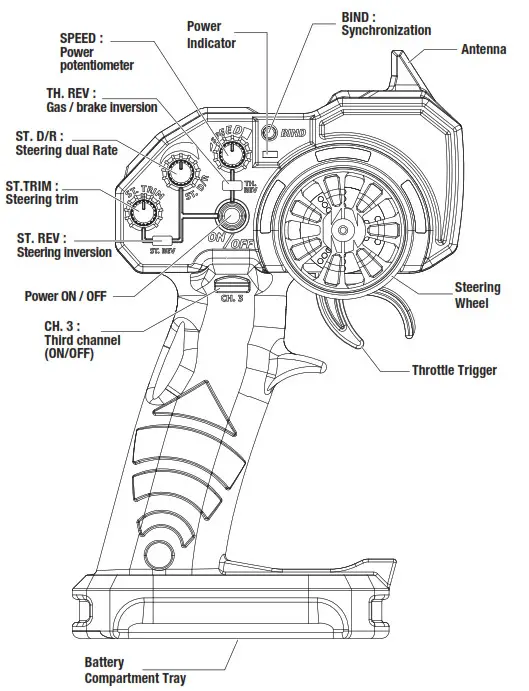
Steering Wheel: Control direction (Left / Right)
Throttle Trigger: Control speed and direction (Forward/Brake/Backward)
Battery Compartment Tray: Cover and hold the batteries powering the transmitter
Power ON / OFF: Power ON / OFF the transmitter
SYNC & Battery Indicator: Top LED light indicates synchronization status and/or adequate battery power supply
CH. 3 : Third channel switch
ST. Trim: Adjust the neutral position of the steering servo when model wheels are straight ahead
ST. REV: Steering inversion
ST D/R: Steering limit switch potentiometer
TH. REV: Throttle/brake inversion
SPEED: Throttle limit switch potentiometer
BIND: Pairing the receiver
KR3X receiver
BAT: Battery connection
CH3: Third channel
CH2: Second channel
CH1: First channel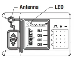
Battery Installation
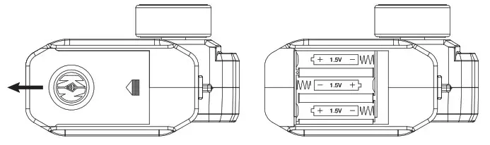
Works with 3 x 1.5V AA Batteries (not provided), KT3X can be operated a few hours. Installation: Remove the battery compartment cover as shown below.
Insert the batteries respecting the polarities indicated in the battery compartment then replace the battery compartment cover
 Battery LED Indicator
– During normal operation, the transmitter LED should be solid green ON, and the receiver LED should be red ON (transmitter & receiver paired).![]() Warning: Never disassemble batteries or put the batteries in fire, chemical agents, otherwise they may cause personal injuries or property damages.
Warning: Never disassemble batteries or put the batteries in fire, chemical agents, otherwise they may cause personal injuries or property damages.
Battery Disposal: Observe corresponding regulations about wasted battery treatment regulations. Submit the wasted batteries to specific recycling stations.
- Pairing your radio
Pairing your receiver to your KT3S+NEO
2. Transmitter turned off, power the receiver On. The receiver LED flashes Red
3. Press and Hold the «BIND/EPA» transmitter button while powering On the transmitter.
The receiver LED becomes solid Red, and the transmitter solid green: your receiver is paired with your transmitter. You can release the «BIND/EPA» button. - Inversion
Reversing is used to change the response direction of the steering wheel and throttle trigger.
Steering Reverse: Reverse the response direction when operating the steering wheel.
Turning left steering wheel, the model turns right while turning right the model turns left.
Throttle Reverse: Reverse the response direction when operating the throttle trigger.
Pushing forward throttle trigger the model moves backward while pulling back, the model moves forward. - Neutral settings (Trim)
KT3X features trimming steering.
Steering Trim Dial: Adjust the neutral position of the steering servo when the wheels are straight ahead. - Steering End Point Adjustment
Steering Dual Rate enables to adjust the same maximum steering angle of servo on both sides (Left and Right) when the model makes steering. The Steering Dual Rate affects the sensitivity of servo. Rotate clockwise = increase maximum steering angle; rotate counterclockwise = reduce maximum steering angle.
The minimum adjustment of Dual Rate (counterclockwise to the max) makes a zero steering angle. - Power adjustment
The power of the throttle can be adjusted using the “SPEED” potentiometer. The further the cursor is turned clockwise, the faster the car will go. It is, therefore, possible, thanks to this slider, to take advantage of the power range of the car from 0% to 100%.
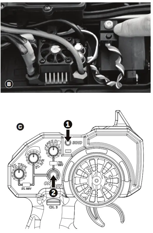
BIND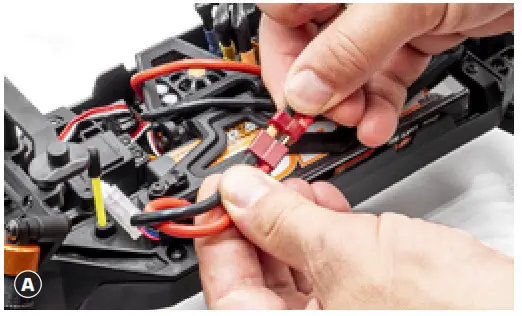 Pairing your receiver to your KT3X
Place the model on a block to prevent the wheels from touching the ground.
A Connect battery to ESC. Fix the wire correctly with the provided connectors.
You must check the signal of the transmitter and receiver before you operate it at first.
Make sure TH Trim is on neutral
– TURN OFF THE TRANSMITTER AND RECEIVER 1.
- Transmitter turned off, power the receiver On B (via ESC).
The receiver LED flashes Red. - Press and Hold the «BIND» transmitter button while powering On transmitter C.
The receiver LED becomes solid Red, and the transmitter solid green: your receiver is paired with your transmitter. You can release the «BIND» button.
HOW TO CONTROL YOUR MODEL (1)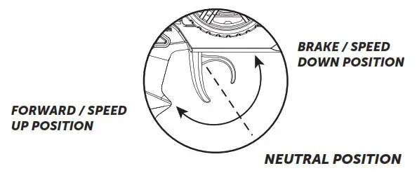
- Pull up the trigger in order to brake or speed down
- Pull the trigger in order to go forward or speed up

80amp KONECT BRUSHLESS WATERPROOF ESC – INSTRUCTION MANUAL
A high power system for the RC model can be very dangerous, so we strongly suggest you read this manual carefully. In that KONECT have no control over the correct use, installation, application, or maintenance of our products, no liability shall be assumed nor accepted for any damages, losses or costs resulting from the use of the product.
ANY CLAIMS ARISING FROM THE OPERATING, FAILURE OF MALFUNCTIONING ETC. WILL BE DENIED. WE ASSUME NO LIABILITY FOR PERSONAL INJURY, OR CONSEQUENTIAL DAMAGES RESULTING FROM OUR PRODUCT OR OUR WORKMANSHIP. AS FAR AS IS LEGALLY PERMITTED, THE OBLIGATION TO COMPENSATION IS LIMITED TO THE INVOICE AMOUNT OF THE AFFECTED PRODUCT.
WARNINGS
- Ensure all wires and connections are well insulated before connecting the ESC to related devices, as a short circuit will damage your ESC.
- Ensure all devices are well connected to prevent poor connection that may cause your vehicle to lose control or other unpredictable issues such as damage to the device.
- Read through the manuals of all power devices and chassis and ensure the power configuration is rational before using this unit.
- Please use a soldering iron with the power of at least 60W to solder all input/output wires and connectors.
- Do not hold the vehicle in the air and rev it up to full throttle, as rubber tires can “expand” to an extreme size or even crack to cause serious injury.
- Stop using the ESC when its casing temperature exceeds 90°C/194°F; otherwise, your ESC will get destroyed and may also get your motor damaged. We recommend setting the “ESC Thermal Protection” to 105°C/221°F (this refers to the internal temperature of the ESC).
- We recommend removing the cooling fan from ESC before exposing the vehicle to liquids and fully dry it right after use.
- Always disconnect the batteries after use, as the ESC will continue to consume current if it’s connected to batteries (even if the ESC is turned off). Long-time contact will cause batteries to completely discharge and result in damage to batteries or ESC. This WILL NOT be covered under warranty.
FEATURES - ESC is compatible with both sensorless and sensored brushless motors (only in sensorless mode).
- Fully waterproof design for all conditions.
- Super internal switch-mode BEC with switchable voltage of 6V/7.4V and cont./peak current of 3A/6A for usage with high torque and high voltage servos.
- A highly reliable electronic switch design prevents mechanical switch failure due to dirt, water, dust and etc.
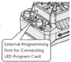
- Separate programming port to easily connect the LED program card or the LCD program box to the ESC.
- Proportional brake with 9 levels of maximum brake force and drag brake force.
- 5 levels of acceleration/punch from soft to aggressive for different vehicles, tires and tracks.
- Capacitor Protection: Innovative Capacitor Protection effectively protects capacitors from exploding and causing irreversible damage to the ESC from overloading.
- Multiple protections: motor lock-up protection, low-voltage cutoff protection, thermal protection, overload protection, and fail-safe (throttle signal loss protection).
- Single-button ESC programming and factory reset.
- Advanced programming via portable LED program card.
SPECIFICATIONS
| Model | KONECT 80AMP WP “by HOBBYWING” |
| Cont. / Burst Current | 80A / 520A |
| Suitable Car | 1/10th & 1/8th Buggy, Short Course Truck, Truck and Monster Truck |
| Motor Turns | From 3000Kv to 5400Kv: any 3650 to 3660 sensorless brushless motor |
| Battery | 6-9 cells NiMH 2-3S Li-Po |
| BEC Output | 6V/7.4V Switchable, Continuous Current of 3A (Switch-mode) |
| Motor Type | Sensored / Sensorless Brushless Motor (only in sensorless mode) |
| Dimension & weight | 49 x 39.5 x 34.7mm (W/Fan) / 105g |
BEGIN TO USE THE NEW ESC
This is an extremely powerful brushless motor system. For your safety and the safety of those around you, we strongly recommend removing the pinion be-fore performing calibration and programming functions with this system, and keeping wheels in the air when you turn on the ESC.
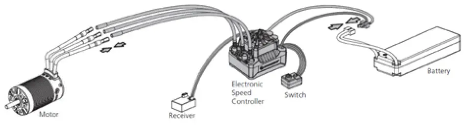
- Connect the ESC, Motor, Receiver, Battery, And Servo The #A, #B, #C wires of the ESC can be connected with the motor wires freely (without any sequence). If the motor runs in the opposite direction, please swap any two-wire connections.
2. Radio Calibration
PLEASE MAKE SURE YOU HAVE ALREADY PROGRAMMED THE TRANSMITTER END-POINTS CALIBRATION (See Transmitter Instructions)
Begin using your ESC by calibrating with your transmitter. If you have these functions, we strongly recommend KONECT users to use the “Fail-Safe” function on the radio system and set (F/S) to “Output OFF” or “Neutral Position”. Example of calibrating Neutral range and Endpoint.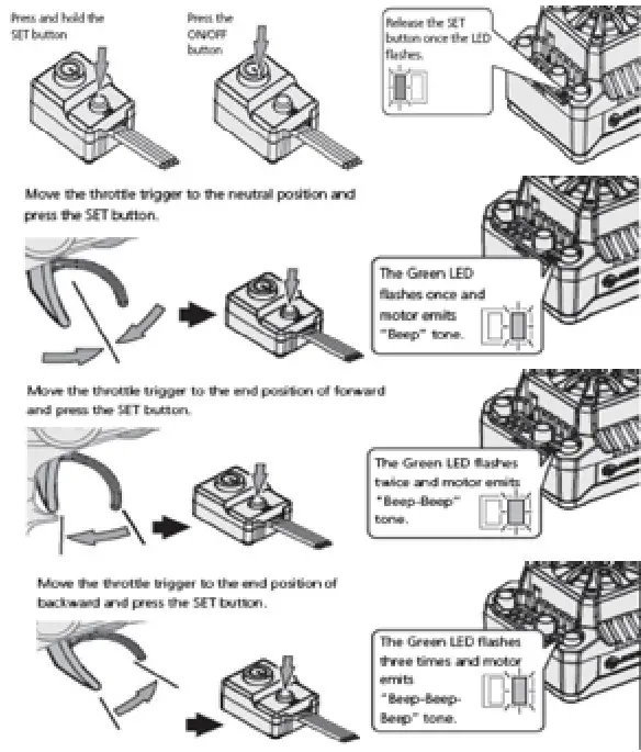
- Turn on the transmitter, ensure all parameters (D/R, Curve, ATL) on the throttle channel are at default (100%). For transmitter without LCD, please turn the TH Dual Rate to the maximum, and the throttle “TRIM” to neutral. For Futaba & KONECT transmitters, the throttle channel shall be set to “REV”, while other radio systems shall be set to “NOR”. Please ensure the “ABS / braking function” of your transmitter must be DISABLED.
- Start by turning on the transmitter with the ESC turned off but connected to a battery. Holding the SET button and press the ON/OFF button, the RED LED on the ESC starts to flash (Note 1 the motor beeps at the same time), and then release the SET button immediately. (The ESC will enter the programming mode if the SET button is not released in 3 seconds, please restart from step 1.) Note 1: Beeps from the motor may be low sometimes, and you can check the LED status instead.
- Set the neutral point, the full-throttle endpoint and the full brake endpoint.
a) Leave the transmitter in a neutral position and press the SET button. After the RED LED dies out, Mode LED flashes GREEN and motor beeps 1 time. A neutral setting is stored. b) Hold full-throttle on the transmitter and press the SET button once. GREEN LED blinks and the motor beeps 2 times. Full throttle setting is stored.
c) Push and hold full brake and press the SET button, the GREEN LED blinks and the motor beeps 3 times. Full brake setting is stored. - The motor will work 3 seconds after the ESC/Radio calibration is complete.
POWER ON-OFF WARNING
- Power ON/OFF: (Start with the ESC turned off), press the ON/OFF button to turn on the ESC; (start with the ESC turned on) press and hold the ON/OFF button to turn off the ESC.
- Warning Tones: Turn on the ESC (that is to turn it on without holding the SET button); the motor will beep the number of LiPo cells you have plugged in. For example, 2 beeps indicate a 2S LiPo, 3 beeps indicate a 3S LiPo.
PROGRAMMABLE ITEMS (THOSE BLACK BACKGROUND AND WHITE TEXT OPTIONS ARE THE FACTORY DEFAULT SETTINGS)
| Programmable Items | Option 1 | Option 2 | Option 3 | Option 4 | Option 5 | Option 6 | Option 7 | Option 8 | Option 9 |
| 1. Running Mode | Fwd/Br | Fwd/Rev/Br | |||||||
| 2. LiPo Cells | Auto Calculation | 2S | 3S | ||||||
| 3. Low Voltage Cutoff | Disabled | Auto (Low) | Auto (Intermediate) | Auto (High) | |||||
| 4. ESC Thermal Protection | 105°C /221°F | 125°C/257°F | |||||||
| 5. Motor Thermal Protection | Disabled | ||||||||
| 6. Motor Rotation | CCW | CW | |||||||
| 7. BEC Voltage | 6.0V | 7.4V | |||||||
| 8. Max Brake Force | 12.50% | 25.00% | 37.50% | 50.00% | 62.50% | 75.00% | 87.50% | 100.00% | Disabled |
| 9. Max Reverse Force | 25.00% | 50.00% | |||||||
| 10. Start Mode (Punch) | Level 1 | Level 2 | Level 3 | Level 4 | Level 5 | ||||
| 11. Drag Brake | 0% | 2% | 4% | 6% | 8% | 10% | 12% | 14% | 16% |
1) Running Mode
Option 1: Forward with Brake,
It has forward and brake functions only and is usually a racing mode.
Option 2: Forward / Reverse with Brake
This mode can be used as for training and it has “Forward/ Reverse with Brake” mode. Hobbywing adopted the “DOUBLECLICK” method, that is your vehicle only brakes on the 1st time you push the throttle trigger forward (brake) (1st push). The motor stops when you quickly release the throttle trigger and then re-push the trigger quickly (2nd push), only then the vehicle will reverse. The reverse function will not work if your car does not come to a complete stop.The vehicle only reverses after the motor stops. This method is for preventing vehicle from being accidentally reversed.
2) Lipo Cells
“Auto Calculation” is the default setting. If LiPo batteries are often used with the same cell count, we would strongly recommend setting this item manually to avoid the incorrect “calculation” (For instance, the ESC may take a not fully charged 3S LiPo as a fully charged 2S LiPo) which may cause the low-voltage cutoff protection to not function ideally.
3) Cutoff Voltage
Sets the voltage at which the ESC lowers or removes power to the motor in order to either keep the battery at a safe minimum voltage (for LiPo batteries). The ESC monitors the battery voltage all the time, it will immediately reduce the power to 50% and cut off the output 10 seconds later when the voltage goes below the cutoff threshold. The RED LED will flash a short, single flash that repeats (☀, ☀, ☀) to indicate the low-voltage cutoff protection is activated. Please set the “Disabled” the “Cutoff Voltage” if you are using Ni-Mh batteries. Warning: If you set the Cutoff Voltage to Disabled when you use a LiPo pack, then please pay attention to the power change of your vehicle. In general, the battery voltage gets pretty low when your vehicle is severely losing power, then you should stop using that pack.
4) ESC Thermal Protection
The ESC will automatically cut off the output with the GREEN LED flashes ( ☀, ☀, ☀) when the temperature gets up to the value you’ve previously preset and activates the ESC Thermal Protection. The output will not resume until the temperature gets down.
5) Motor Thermal Protection
This item has been permanently set to “None” by the manufacturer.
6) Motor Rotation
Pull the throttle trigger with the motor shaft facing you, the motor spins counterclockwise. When this item is set to CCW; the motor spins clockwise. When it is set to CW. The (A/B/C) wiring order of motors from different manufacturers may vary, so do the direction of the motor rotations. You can adjust the “Motor Rotation” or swap any two (ESC-to-motor) wires if the motor runs in reverse.
7) BEC Voltage
Option 1: 6.0V It’s applicable to ordinary servos. Do not use this option with high voltage servos; otherwise, your servos may not function normally due to insufficient voltage.
Option 2: 7.4V It’s applicable to high voltage servos. Do not use this option with ordinary servos; otherwise, your servos may be burnt due to high voltage.
8) Max. Brake Force
The ESC provides a proportional braking function; the braking effect is decided by the position of the throttle trigger. It sets the percentage of available braking power when the full brake is applied. A large amount will shorten the braking time but it may damage your pinion and spur. Please select the most suitable brake amount as per your car condition and your preference.
9) Max. Reverse Force
The different reverse amounts will bring different reversing speeds. For the safety of your vehicle, we recommend using a low amount.
10) Start Mode / Punch
You can choose the punch from level 1 (very soft) to level 5 (very aggressive) as per the track, tires, grip, and conditions. This feature is very useful for preventing tires from wheel-spinning during the warm-up process. In addition, “level 4” and “level 5” have strict requirements on the battery’s discharge capability. It may affect the starting-up if the battery discharges poorly and cannot provide large current in a short time. If the car stutters or suddenly loses power in the starting-up process, indicates that the battery’s discharge capability is poor, you might need to reduce the punch or increase the FDR (Final Drive Ratio).
11) Drag Brake
Drag brake is the braking power produced when releasing from full speed to neutral zone. This is to simulate the slight braking effect of a neutral brushed motor while coasting. (Attention! Drag brake will consume much power, so apply it cautiously.)
ESC PROGRAMMING
1) Programming your ESC with the SET button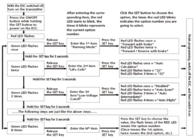
Note 2:
a) For easy recognition, the motor beeps at the same time when the GREEN LED flashes.
b) When “N” (the number) is equal to or bigger than 5, we use a long flash to represent “5”. For example, the GREEN LED flashes a long flash (and the motor beeps a long beep at the same time) indicating you are in the 5th programmable item; if the GREEN flashes a long flash and a short flash (and the motor beeps a long beep and a short beep at the same time) indicating you are in the 6th programmable item; a long flash and two short flashes ( a long beep and two short beeps at the same time) indicating you’re in the 7th programmable item and so on.
2) Program your ESC with a LED program card # KN-PROGRAM CARD
The portable LED program card is an optional accessory applicable for field use. Its friendly interface makes ESC programming easy and quick. Before the programming, you need to connect your ESC and the program card via a cable with two JR male connectors (as shown below), and then turn on the ESC, all programmable items will show up a few seconds later. You can select the item by choosing via the “ITEM” & “VALUE” buttons on the program card. Press the “OK” button to save all new settings to your ESC.
Note 3: the programming port of this ESC is also the fan port, so you need to unplug the fan first and then plug (one end of) the programming cable in the PRG/FAN port and the other end (of the programming cable) in the ESC port on the LED program card. Please don’t use the throttle control cable (also called Rx cable) on the ESC to connect the program card/box, otherwise, the program card/box won’t function.
FACTORY RESET
- Restore the default values with the SET button
Press and hold the SET button for over 3 seconds anytime when the throttle trigger is at the neutral position (except during the ESC calibration and programming) can factory reset your ESC. RED & GREEN LEDs flash simultaneously indicating you have successfully restored all the default values within your ESC.Once you power the ESC off, and then back on, your settings will be back in the default mode. - Restore the default values with a LED program card After connecting the program card to the ESC, press the “RESET” button and the “OK” button to factory reset your ESC.
TROUBLESHOOTING
| TROUBLE | POSSIBLE REASON | SOLUTION |
| After power on, the motor doesn’t work, and the cooling fan doesn’t work | No power was supplied to the ESC. | Check if all ESC & battery connectors have been well soldered or firmly connected. |
| The ESC switch was damaged | Replace the broken switch. | |
| After power on, the motor can’t work, but emits a “beep-beep-, beep-beep-” alert tone. (Every “beep-beep-” has a time interval of 1 second ) | Input voltage is abnormal, too high or too low | Check the voltage of the battery pack |
| After the ESC was powered on and finished LiPo cells detection (the GREEN LED flashed N times), and then the RED LED flashed rapidly. | The ESC didn’t detect any throttle signal. | Plug the control wire into the throttle channel of the receiver correctly. |
| The neutral throttle value stored on your ESC is different from the value stored on the transmitter | Re-calibrate the throttle range after you release the throttle trigger to the neutral position. | |
| The motor runs in the opposite direction when it is accelerated | The (ESC-to-motor) wiring order was incorrect | Swap any two-wire connections between the ESC and the motor. |
| Your chassis is different from popular chassis. | ||
| The motor suddenly stops running while in working state | The throttle signal is lost | Check the transmitter and the receiver Check the signal wire from the throttle channel of your receiver |
| The ESC has entered the Low Voltage Protection Mode or Over-heat Protection Mode | Red LED flashes means Low Voltage. Green LED flashes means Over-heat. | |
| The motor stuttered but couldn’t start. | Some soldering between the motor and the ESC was not good. | Check all soldering points, please re-solder if necessary. |
| The ESC was damaged (some MOSFETs were burnt). | Contact the distributor for repair or other customer services. | |
|
The vehicle could run forward (and brake), but could not reverse. | The throttle neutral position on your transmitter was actually in the braking zone. Set the “Running Mode” improperly. | Re-calibrate the throttle neutral position. No LED on the ESC will come on when the throttle trigger is at the neutral position. |
| Set the “Running Mode” improperly. | Set the “running mode” to “Forward/Reverse with Brake”. | |
| The ESC was damaged. | Contact the distributor for repair or other customer services. | |
| The car ran forward/backward slowly when the throttle trigger was at the neutral position. | The neutral position on the transmitter was not stable, so signals were not stable either. | Replace your transmitter |
| The ESC calibration was not proper. | Re-calibrate the throttle range or fine tune the neutral position on the transmitter. | |
| The LED program card kept display 3 short lines (- – -) after you connected it to your ESC. | The programming card/box was connected to the ESC via the throttle control cable (Rx cable). | It is wrong to use the Rx cable to connect the programming card/box. The programming port of this ESC is also the fan port, so please connect the ESC and programming card/box by plugging the programming cable into the fan port. |
| When pressing the SET button to set the throttle neutral position, the GREEN LED didn’t flash and no beep was emitted, or you were unable to set the full-throttle endpoint and the full brake endpoint after the neutral position was accepted. | The ESC throttle cable wasn’t plugged in the correct channel on the receiver. | Plug the throttle cable into the throttle (TH) channel on your receiver. |
| The ESC throttle cable was reversely plugged in. | Plug in the throttle cable properly by referring to the relevant mark shown on your receiver. |
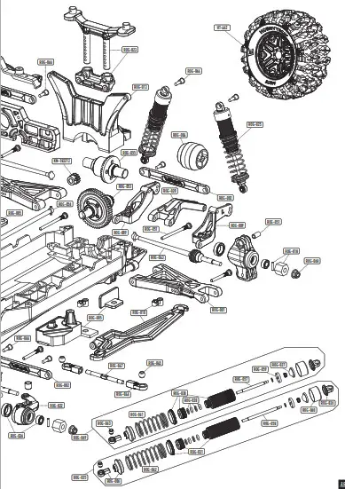
| ITEM | DESIGNATION |
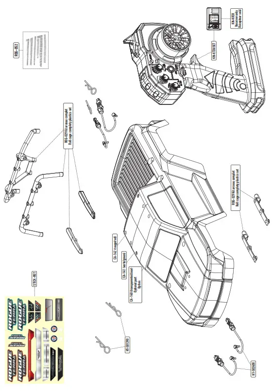
| CA-140 | Lexan® Rogue Terra clear body |
| CA-141 | Green Rogue Terra Body |
| CA-142 | Red Rogue Terra Body |
| HT-462 | « TERRAMAX »140/73 12mm Hex Tyres completely set |
| HT-501390 | Universal 1/8 body clips (10pcs) |
| HT-502400 | Body clips retainers |
| KN- 0711LVMG | Digital servo 7kg-0.11s metal gear |
| KN-183212 | 12T pinion gear alloy steel 32dp ø5mm + 3,17 adapter |
| KN-3660- 2200 | 3660 SCT 2200KV Brushless motor |
| KN-8BL80- SCT-WP | Waterproof Brushless 80A SCT ESC |
| KN-KR3X | 2.4 GHZ Receiver for transmitter KT3X (3 channels) |
| KN-KT3X/ SET | Konect KT3X 2.4 GHZ radio set |
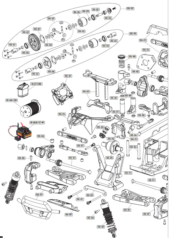
| ROG-001 | Suspensions Arms |
| ROG-002 | Plastic upper tie-rod |
| ROG-003 | Servo horn and ball end |
| ROG-004 | Wheelie bar wheel |
| ROG-005 | ESC holder plastic set |
| ROG-006 | Shocks Rod-end with spring maintain |
| ROG-007 | Front gear box lower protect |
| ROG-008 | Steering plastic parts set with spring |
| ROG-009 | Wheelie bar L/R arms |
| ROG-010 | Battery holder |
| ROG-011 | Main chassis |
| ROG-012 | Front gear box in 2 parts |
| ROG-013 | Rear shocks tower |
| ROG-014 | Front gear box upper plate |
| ROG-015 | Plastics motor holder set |
| ITEM | DESIGNATION |
| ROG-016 | Aluminum motor holder |
| ROG-017 | Steering plate |
| ROG-018 | Plastics wheel hub hex + pins (x4) |
| ROG-019 | Front bumper |
| ROG-020 | Wheelie bar upper holder |
| ROG-021 | Front C-hub |
| ROG-022 | Front L/F steering knuckles |
| ROG-023 | Body hol |
| ROG-024 | Rear Hub |
| ROG-025 | Rear shocks absorber completely set |
| ROG-026 | Upper shocks plastics mounts |
| ROG-027 | Shocks Bladder |
| ROG-028 | Shocks o-ring rebuilt kit |
| ROG-029 | Roll cage complety plastics set |
| ROG-030 | Front shocks bodies |
| ROG-031 | Rear shocks bodies |
| ROG-032 | 32 Pitch Center Spur gear |
| ROG-033 | Differential drive cups shims |
| ROG-034 | Bevel Gear 16T |
| ROG-035 | Bevel Gear 16T shaft |
| ROG-036 | Ball-bearing completely set |
| ROG-037 | Differential gaskets |
| ROG-038 | Differential drive cups O-ring |
| ROG-039 | Differential pinions complety set |
| ROG-040 | 39T Large Bevel Differential Gear |
| ROG-041 | Center differential drive cup set |
| ROG-042 | F/R differential drive cup set |
| ROG-043 | Front or rear CVD driveshafts (x2) |
| ITEM | DESIGNATION |
| ROG-044 | Servo saver shaft |
| ROG-045 | Metal ball for steering rod end |
| ROG-046 | Steering 4 mm rod end |
| ROG-047 | Steering Turnbuckle M4 |
| ROG-048 | Steering stop bushing |
| ROG-049 | Aluminium front lower arm holder |
| ROG-050 | Front C-hub special screws |
| ROG-051 | Arms ans Hub specials shafts |
| ROG-052 | Screws complety set without specials shafts |
| ROG-053 | Center differential |
| ROG-054 | Differential case |
| ROG-055 | Front or Rear differential |
| ROG-056 | Center Drive Shaft |
| ROG-057 | Front shock shaft |
| ROG-058 | Rear shock shaft |
| ROG-059 | Shocks pistons |
| ROG-060 | Aluminium shocks caps |
| ROG-061 | Front shocks springs |
| ROG-062 | Rear shocks springs |
| ROG-063 | Ball for shocks rod end |
| ROG-064 | Front gear box drive cup |
| ROG-065 | Steering system bushing |
| ROG-066 | Shocks and tie-rod special screws |
| ROG-067 | Motor fan with alminium holder |
| ROG-068 | M4 Nylon nuts |
| ROG-069 | Front shocks absorber complety set |
| ROG-070 | Differential case bushings |
| STICK-RGT | Stickers Rogue Terra |
 |  |  |


