![]()
RTU5023 Wireless Temperature Control System
User Manual
Inquiry Onsite value with a FREE Call or SMS! High-Low Threshold alarm with SMS text Message alert! Interval Report Status to Your Mobile Phone by SMS!
GSM/GPRS/3G/4G/Cloud Temperature&Humidity&Analog &Voltage&Power Status Alarm Temperature&Humidity&Analog &Voltage&Power Status Alarm
User Manual
Ver 2.5 RTU5023/6/7/8/9 Date Issued: 2020-12-15 All rights reserved by King Pigeon Hi-Tech. Co., Ltd.
www.iot-solution.com
This handbook has been designed as a guide to the installation and operation of RTU5023,RTU5026,RTU5027, RTU5028,RTU5029 temperature&humidity&analog&voltage&power status alarm and monitor. Statements contained in the handbook are general guidelines only and in no way are designed to supersede the instructions contained with other products. We recommend that the advice of a registered electrician be sought before any Installation work commences. King Pigeon Hi-Tech.Co., Ltd, its employees and distributors, accept no liability for any loss or damage including consequential damage due to reliance on any material contained in this handbook. King Pigeon Hi-Tech.Co., Ltd, its employees and distributors, accept no liability for GSM Network upgrading or SIM Card upgrading due to the technology specifications contained in this handbook.
UPGRADE HISTORY
DATE | VERSION | DESCRIPTION |
| 2015-09-10 | Ver1.0 | RTU5023 Origin Version |
| 2018-08-01 | Ver2.0 | RTU5023/6/7/8/9 New Version |
| 2018-08-11 | Ver2.1 | Add continue dialing function(avoid alarm calling is transferred to voicemail leads to user missed alarm reminding) |
| 2019-01-24 | Ver2.2 | Upgrade dial & data offline reconnection function;Modify RTU5023/5026/5027 Alarm Verify Time to”0”(Alarm immediately). |
| 2019-09-20 | Ver2.3 | Modify the server default parameters, increase the default registration mechanism(Login Message) |
| 2019-11-30 | Ver2.4 | Add 5023/5026/5027 Alarm Verify Time modification instruction. |
| 2020-12-15 | Ver2.5 | RTU5028 adds voltage over-high/low-limit alarm function |
***Strongly recommend you use the APP to program it***
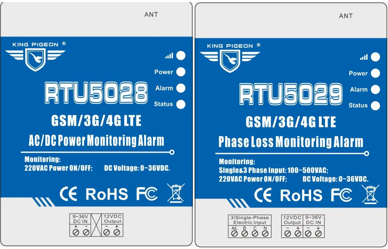
Model List
Model | GSM/3G/4G | Description | Input/Output Type | DC Input |
| RTU5023 | Optional | Environmental Monitoring Alarm | AM2301 Temperature&Humidity Sensor | 9~36VDC |
| RTU5026 | Temperature Monitoring Alarm | DS18B20 Temperature Sensor | ||
| RTU5027A | Analog Transducer Monitoring Alarm | 4~20mA Analog Input | ||
| RTU5027V | Analog Transducer Monitoring Alarm | 0~5V Analog Input | ||
| RTU5028 | AC/DC Power Monitoring Alarm | 12VDC Output | ||
| RTU5029A | Phase Loss Monitoring Alarm | 3 Phase Input,12VDC Output | ||
| RTU5029B | Phase Loss Monitoring Alarm | Single Phase Input,12VDC Output |
Brief introduction
RTU5023/6/7/8/9 provides 1 input for temperature,humidity, analog, power voltage, power status monitoring, and alarm. When the temperature, humidity, and power voltage exceed high threshold or low threshold value, will send an SMS alert to up to 10 preset mobile phones immediately.
Just dial from the authorized user number, the Monitor Alarm unit will reject at the first “Ring”, no communication cost, and then return the current temperature, humidity, power status, or voltage.It can report the current status intervals or daily. Moreover,it can also support Modbus RTU Over TCP and Modbus TCP to connect to the cloud platform, then monitor the current status in real-time through GSM/3G/4G network.
RTU5023/6/7/8/9 Monitor Alarm unit can be used for temperature,humidity,4~20mA/0~5V analog signal, DC voltage,3 phase power status,single-phase power status monitoring and alarm, suitable for classrooms, public places, hospitals, stations, Food warehouses, offices, factories, libraries, laboratories, etc., and any place that requires and supports monitoring.
Safety Directions
![]() Safe Startup
Safe Startup
Do not use GSM units when using GSM equipment is prohibited or might bring disturbance or danger.
Interference![]() All wireless equipment might interfere network signals of GSM unit and influence its performance.
All wireless equipment might interfere network signals of GSM unit and influence its performance.
Standard Packing List
Monitor Alarm unit X 1; Antenna X 1; AC/DC adaptor( DC12V 1.5A ) X1 ;User manual X 1.
Note: The package does not include any SIM card.
Optional: AM230x Temperature &Humidity Sensor, cable length 1m,5m,20m DS18B20
Temperature Sensor,cable length 1m,5m,10m,20m
SR-x Siren DIN 35mm Standard DIN rail fixed Bracket:
Mainly Features
- GSM/GPRS/3G/4G network communication can be operated from anywhere, at no distance;
- Multiple applications: temperature, humidity, power supply voltage, analog signal,3 phase power status, single-phase power status, etc.;
- Inbuilt MCU monitoring power supply input voltage value, measure range is 0~36V, no need for the additional sensor to save cost;
- Up to 10 authorized phone numbers, 5 can be used to receive calls or SMS, and 5 can be used to call and SMS while alarming occurrence;
- Can set timer report and every x hours automatically send its status/value to the first authorized number;
- Support remotely read historic data via SMS;
- A rechargeable backup battery inside can last 8 hours;
- Modular structure design, replace a module can upgrade the network from 2G to 3G/4G or 3G to 4G;
- Compatible wall installation and DIN35mm industrial rail installation;
- Support Modbus RTU Over TCP and Modbus TCP, which can be connected to a cloud platform.
Technical specifications
| Item | Reference Scope |
| DC Power supply | Standard adapter:12VDC, Range 9~36VDC |
| Power consumption | Standby:20mA@12V; Working Max:150mA@12V |
| GSM/3G/4G | GSM frequency: 850/900/1800/1900MHz 3G/4G: Optional: WCDMA/TDD-LTE/FDD-LTE |
| SIM interface | Support 3V SIM Card |
| External antenna | SMA Antenna interface, 50 Ohm, Gain: 3dB |
| Protocol | Modbus RTU Over TCP, Modbus TCP |
| Temp.&Hum Inputs | AM230x:temperature range -40℃~80℃,accuracy±0.5℃, humidity range 0~99%RH,accuracy ±3%RH DS18B20:temperature range -55℃~125℃,accuracy ±0.5℃ |
| Analog input | 4~20mA or 0~5V |
| Phase power input | Phase power voltage:100~500VAC |
| Backup Battery | 3.7V/900mAh can last 8 hours |
| Working temperature | -10℃~60℃ |
| Working Humidity | Relative humidity 95% (condensation free) |
| Exterior dimension | 70mm * 88mm * 30mm |
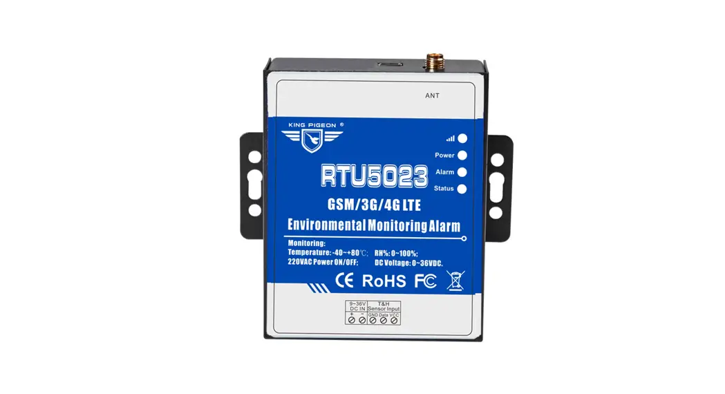
Physical Layout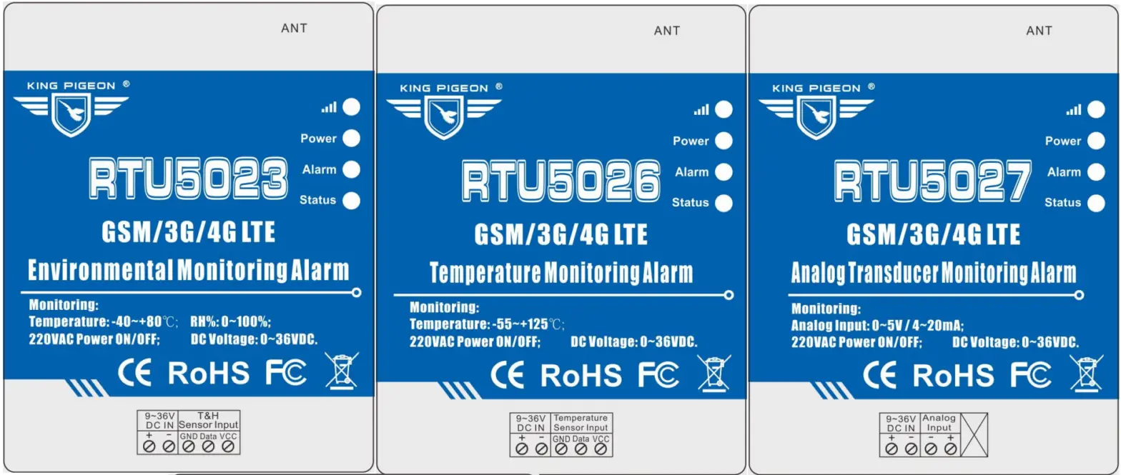
6.1 LED Indicator Instruction LED Indicator Instruction
| LED Indicator Instruction | |
|
| Cellular network indicator: 2G module, flashing quickly (flash per 0.8s) means searching for cellular or no network; flashing slowly(flash per 2s) means registering successfully. 3G/4G module, when searching for cellular or no network, the light will 2seconds flick once; registered successfully will be on 2s, off 1s..Flicks quickly mean data transmission. |
| Power indicator:LED ON when connecting power; otherwise,it is OFF | |
| Alarm Indicator: Alarm will ON.; Normally is OFF; | |
| Status Indicator: Arm is ON; Disarm is OFF | |
6.2 Interface Instruction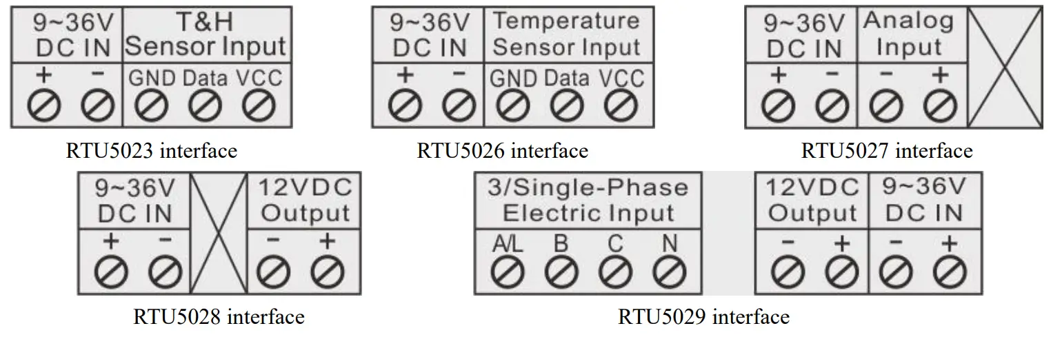
| Interface instruction | ||
| 9~36V DC IN | + | DC9~36V positive input |
| – | DC9~36V negative input | |
| T&H Sensor Input (RTU5023) | VCC | DC3.3V output, connected with AM230x VCC power wire(red) |
| Data | Connected with AM230x Data wire(yellow) | |
| GND | Connected with AM230x GND wire(black or white) | |
| Temperature Sensor Input (RTU5026) | VCC | DC3.3V output, connected with DS18B20 VCC power wire(red) |
| Data | Connected with DS18B20 Data wire(yellow) | |
| GND | Connected with DS18B20 GND wire(black or white) | |
| Analog Input (RTU5027) | + | 4~20mA or 0~5V analog positive input |
| – | 4~20mA or 0~5V analog negative input | |
| 12VDC Output (RTU5028、RTU5029) | + | 12VDC positive output |
| – | 12VDC negative output | |
| 3/Single-Phase Electric Inp(RTU5029) | A/L | Three-phase A phase input or single-phase firewire input |
| B | Three-phase B phase input | |
| C | Three-phase C phase input | |
| N | Three-phase or single-phase null wire input | |
| ANT | GSM/3G/4G antenna interface | |
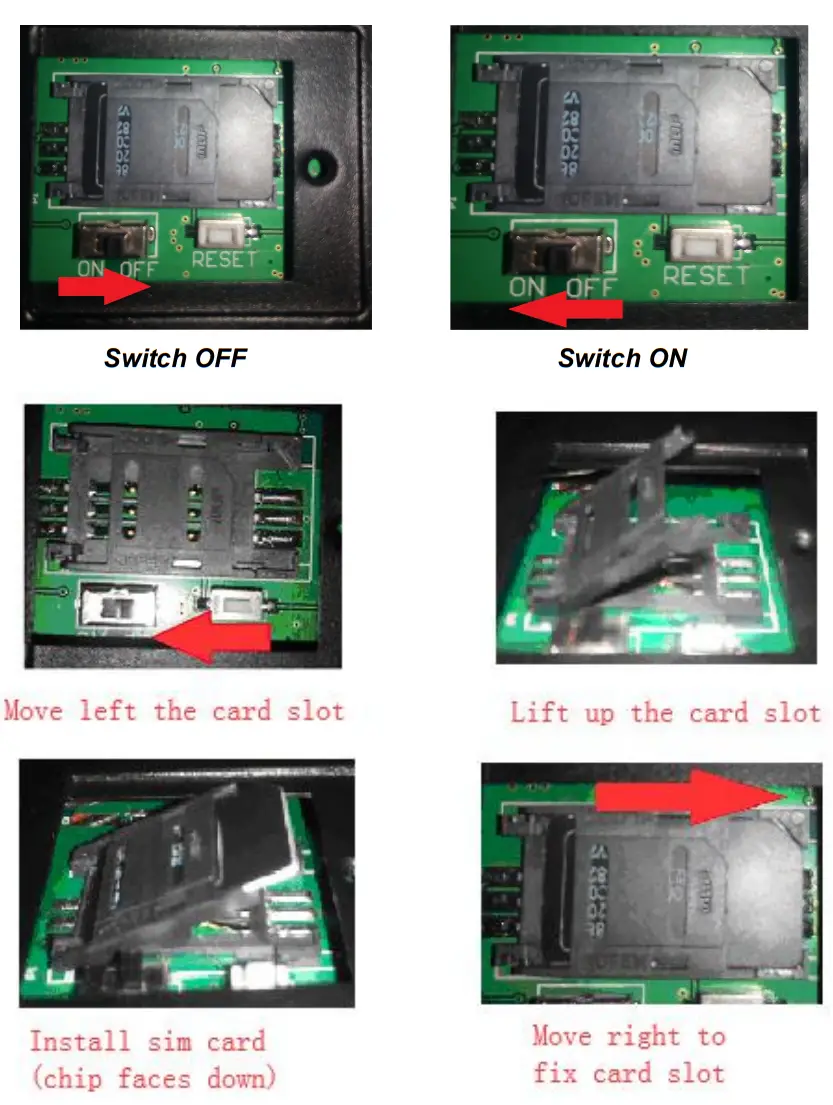
6.3 Backside Switch & Card Slot
At the backside of the panel, please use the tool to remove the screw, and you can see the switch button, RESET button(reset button has the function:
- upgrade, press it, and switch on the device will enter the upgrade state;
- .reset, press it then hold on 3 seconds in the state of power on will reset ) and card slot as below:
Reset the unit
- Switch on the device, press and hold the RESET button for 3 seconds, after power indicator flash 3 times,the device will reset successfully.
- Sending SMS command “password+RESET “,receive returns SMS “Reset successfully”,means device is reset successfully.
Settings&Operation
***Strongly Recommend using the APP to program it***
Notice:
- The default Password is 1234.
- The unit cannot support PIN Code Protected SIM Card
- You can program the unit with SMS commands using your phone.
- Remember that commands must be CAPITAL LETTERS. It is PWD not pwd, CAP not Cap, etc. Don’t add spaces or any other character.
- The PWD in the commands is means the password, when you use it, please a stand it by the digital number; the capital letter PWD is the command letter, use PWD directly.
- Some GSM/3G operators use different SMS parameters; the units can’t return the SMS confirmation in some gsm operators, but it can perform the functions correctly. Also, you can try to add the country code before the number, see the below settings:
For example:
E.g.: the country code is 0086, or +86.
The user cell phone number is 13600000000 and has been assigned as a SMS Alert number, the sim card number in the panel is 13512345678.
When you set up the number as the authorized number, please setup as 008613600000000 or +86136000000000. Not 13600000000. - If the password is correct but the command is incorrect, the RTU502x will return: SMS Format Error, Please check Caps Lock in Command! So please check the Command, or add the country code before the telephone number or check the input is in ENGLISH INPUT METHOD and CAPS LOCK. If password incorrect then will not any response SMS.
- Once the GSM/3G Unit received the SMS Command, will return SMS to confirmation, if no SMS return, please check your command or resend again.
- The SMS commands that you will certainly use in the GSM units are the following:
**SMS Commands For Program and Operation the RTU50236789**
1) Setup the RTU502x SIM Card Number (Max 21 digits)
This number is used for automatically adjust the time from GSM Operator.
Command | Return SMS | Example | |
| PWD+TEL+x+# x stands for the unit phone number, max 21 digits | Set success! | 1234TEL008613570810254# | |
| Stands for the unit phone number is 13570810254 | |||
2) Setup RTU502x system Time Command
Command | Return SMS | Example | |
| Setup | PWD+D20xx-yy-zz+Thh:mm or PWD+Dxxyyzz+Thhmm Notice: xx(year),yy(month),zz(day),hh(hour), mm(minute) | xx(Y)xx(M)xx(D)xx(H)xx(M) | 1234D2018-01-02T03:04 |
| 1234D180102T0304 | |||
| Stands for 03:04, January 2,2018 | |||
| Inquiry | PWD+D#T# or PWD+D | xx(Y)xx(M)xx(D)xx(H)xx(M)) | |
3) Modify Password (4digits, Default is: 1234)
Command | Return SMS | Example |
| PWD+P+new password | [new password], This is the New Password, please remember it carefully. | 1234P4321 stands for change |
| password from 1234 to 4321 |
4) Armed or Disarmed Command
Command | Return SMS | Example | |
| Armed | PWD+AA | Armed | Armed stands for while alarm occurrence will send SMS or dial to alert users. |
| Disarmed | PWD+BB | Disarmed | Disarmed stands for while alarm occurrence, will not send SMS or dial to alert users. |
5) Setup Authorized User number
- (Total 10 authorized numbers, each number max 21 digits.)
- When alarm/Recovery occurs, the RTU502x will send predefined SMS to the 1st ~5th numbers, and send SMS also dial 6th ~10th numbers, till anyone answers it or cycle dial 3 times.
- Just dial from Authorized User number, the RTU502x will reject at the first “Ring”, with no communication cost, and then return the current temperature, humidity, power voltage by SMS.
- The 1st number can also receive daily report SMS.
Command | Return SMS | |
| Setup | PWD+A+x+T+y (x= 01~10,must be 2 digits,stands for series number) (y stands for phone number,max 21 digits,supports add country code,e.g. +86 or 0086)e.g.: 1234A03T008613570810254 to setup 008613570810254 as the 3rd number. | 1: — 2: — 3: 13570810254 4: — |
| Inquiry | PWD+A | Return All numbers |
| Remove | PWD+A+x | |
6) Setup Alarm Parameter 1
| Command | Return SMS | |
| Setup Channel Name | PWD+AIN+x+T+y x=1,2,3;1 stand for temperature or analog input,2 stands for humidity,3 stands for voltage(below x are the same)y stands for channel name,max 20 characters | Temperature/AIN:y Humidity:y Voltage:y |
| Inquiry | PWD+AIN123 | |
| Setup Threshold Value | PWD+AINR+x+L+y+H+z+# y stands for low threshold value;z stands for high threshold value,if y=z,will not alarm RTU5023 valid temperature range:-400~800(stands for 40℃~80℃); RTU5026 valid temperature range:-550~1250(stands for -55℃ ~125℃); Temperature/AIN: low:y,High:z.= Humidity valid range:0~100(stands for 0%RH~100%RH); Voltage valid range:0~370(stands for 0V~37V); Analog signal range:-32767~32767(stands for -3276.7~3276.7); Humidity: Low: y,High: z. When sending SMS command to set up, except humidity should be Voltage: set up according to the actual value,the temperature, voltage and analog Low: y, High: z. value should be set up at 10 multiples of the actual value.If setup by APP, all of them can be set up according to the actual value.Recommended using the APP for setting.E.g.1234AINR1L-120H356#to setup temperature low threshold as | |
| -12.0℃,high threshold as 35.6℃; 1234AINR2L10H90# to setup humidity low threshold as 10%RG,high threshold as 90%RH | ||
| Inquiry | PWD+AINR | |
| Setup Analog Measurement value range (Used for RTU5027) | PWD+AINML+y+H+z+# y,z=-32767~32767;y stands for min value,z stands for max value; RTU5027A default min is 40,max is 200(corresponds to 4mA,20mA); RTU5027V default min is 0,max is 50(corresponds to 0V,5V)When sending SMS command to set up,the value should be set up at 10 multiples of the actual value;If setup by APP can be set up according to the actual value. Recommended using the APP for setting.E.g.1234AINML-13579H24680# to set up min value as -1357.9,max value as 2468.0 | AIN: Min:y, Max:z |
| Inquiry | PWD+AINM | |
| Setup Alarm Verify Time | PWD+AIN+x+Q+y x=1,2,3;1 stand for temperature or analog input,2 stands for humidity,3 stands for voltage y=0~255 seconds; temperature, humidity, analog quantity default 5seconds, voltage default 2 seconds | AINQ1:y(S) AINQ2:y(S) AINQ3:y(S) |
| Inquiry | PWD+AINQ |
Setup Alarm Parameter 2
| Command | Return SMS | |
| Setup Device Name | PWD+DN+y y stands for device name,max 60 characters | Device Name:y |
| Inquiry | PWD+DN | |
| Setup Alarm Verify Time | RTU5028: PWD+AINQ+y RTU5029: PWD+AIN+x+Q+y x=1,2; 1 stands for external power supply,3 stands for single/three-phase power y=0~65535 seconds, default 2 seconds,0 stands for alarm immediately | The verification time of External Power Goes OFF: y Seconds AINQ1:y Seconds AINQ2:y Seconds |
| Inquiry | PWD+AINQ | |
| Setup Power Failure Alarm Content | RTU5028:PWD+AINA+y RTU5029:PWD+AINA+x+T+y x=1,2; 1 stand for External power supply,3 stands for single/three-phase power y stands for power failure alarm content, max 40 characters | Alarm Content: y AINA1: y ANIA2: y |
| Inquiry | PWD+AINA | |
| Setup Power Recover Content | RTU5028: PWD+AINN+y RTU5059: PWD+AINN+x+T+y x=1,2; 1 stands for External power supply,3 stands for single/three-phase power | Recover Content: y AINN1: y ANIN2: y |
| y stands for power recovery alarm content, max 40 characters | ||||||
| Inquiry | PWD+AINN | |||||
| Setup 12V Output Time | PWD+AOT+y y=0~65535 seconds,default 120 seconds,0 stands for always keep output | 12V Output: y Seconds | ||||
| Inquiry | PWD+AOT | |||||
| Open 12 V Output | PWD+AON | 12V Output: ON/OFF | ||||
| Close 12 V Output | PWD+AOF | |||||
| Inquiry | PWD+AOE | |||||
| Set voltage channel name (Only for 5028) | Password+AIN+3+T+y Note: y is the channel name, which supports up to 60 characters (1 Chinese character occupies 2 characters); Example:Set the voltage channel name to voltage, |
Voltage:y | ||||
| command | 1234AIN3T Voltage | |||||
| Inquiry (Only for 5028) | PWD+AIN3 | |||||
| Setup Threshold Value | Password+AINR+3+L+y+H+z+# Note: y is the low threshold, z is the high threshold. If the high and low thresholds are set to be the same, there will be no alarm. The default is 0; the Voltage setting range is 0~370 (corresponding to 0V~37V); When setting the command, the voltage should be set 10 times of the actual value. For example, if the voltage is 12V, the set value should be 120; if you use APP to set, all the actual values can be used. It is recommended to use APP to set it. Example: Set the low threshold voltage to 9V and high threshold value to 15V, command |
Voltage: Low: y,High: z. | ||||
| 1234AINR3L90H150# | ||||||
| Inquiry (Only for 5028) | PWD+AINR | |||||
1) Setup Daily Report Time (Default is 10:00 AM)
The daily report is an everyday report of the RTU502x current status by SMS to the 1st Authorized number.
The content is the same as the return SMS of command “PWD+EE”.
| Command | Return SMS | |
| Setup | PWD+DRT+hh:mm hh stands for an hour; mm stands for a minute, must be 2 digits | Daily SMS Report at:hh: mm |
| Inquiry | PWD+DRT | Daily SMS Report at HH: MM |
| Delete | PWD+DRTDEL | Daily SMS Report at: |
Setup Interval Report Time
The interval report is an interval to report the current status by SMS to the 1st Authorized number.
The content is the same as the return SMS of command “PWD+EE”.
| Command | Return SMS | |
| Setup | PWD+DT+x | Report status every xxx hours |
| (xxx=001-998hours, must be 3digits,default 999,stands for disable report) | ||
| Inquiry | PWD+DT |
Inquiry Current Status (We recommend user inquiry it by a call from authorized numbers)
| Command | Return SMS |
| PWD+EE | Armed/Disarmed; Device Name;(for RTU5028/9) A Phase:[Normal/Loss]; (for RTU5029A) B Phase:[Normal/Loss]; (for RTU5029A) C Phase:[Normal/Loss]; (for RTU5029A) Single Phase: Normal/Loss;(for RTU5029B) External Power Normal/Failure: Current value;(for RTU5028/9) AIN:Current Value,[Normal/Higher/Lower];(for RTU5027) Temp:xxxxC,[Normal/Higher/Lower];(for RTU5023/6) Humi:xxxxRH%,[Normal/Higher/Lower];(for RTU5023) Volt:xxxxVDC,[Normal/Higher/Lower];(for RTU5023/6/7) GSM Signal Value: IMEI: Model: Version: |
Inquiry Historic Record (Only can inquiry the latest 100 alarm )
| Command | Return SMS | Example |
| PWD+HIS+x(x=1-100,stands for inquiry qty) | [IMEI Code as Device ID] 2015-07-15,18:18 1:[Current Value] °C,[Higher/Lower/Normal] 2015-07-15,18:18 2: [Current Value]RH%,[Higher/Lower/Normal] 2015-07-15,18:18 3: [Current Value]VDC,[Higher/Lower/Normal] (0: Analog input, 1: Temperature, 2: Humidity, 3: Voltage. Each SMS will include one IMEI Code as Device ID.) | PWDHIS5 to read the latest 5 historic records. |
Remotely Reboot
| Command | Return SMS | Example | |||
| Setup Periodicity Reboot | PWD+REBOOT+x (xxxx=0-9999 hours, default is 160 hours) | Reboot: x Hours | 1234REBOOT3 | The device will be | |
| reboot automatically for every 3 hours. | |||||
| Inquiry | PWD+RE | ||||
| Reboot Manually | PWD+RT | No return SMS | |||
Remotely Reset
| Command | Return SMS | |
| Remotely Reset | PWD+RESET | Reset successfully |
Setup Device ID
| Setup | PWD+ID+x x=0~65535,default is 1. If the device choose the Modbus protocol,x=1~247 | ID:x |
| Inquiry | PWD+IDE |
Setup GPRS/3G/4G Parameter
| Command | Return SMS | |
| Setup | PWD+AP+x+#+y+#+z x stands for APN,y means user name,z means the password | APN:x User name:y Password:z |
| Inquiry | PWD+AP | |
| Delete | PWD+APDEL | |
Setup GPRS/3G/4G Parameter
| Command | Return SMS | |
| Setup | PWD+AP+x+#+y+#+z x stands for APN,y means user name,z means the password | APN:x User name:y Password:z |
| Inquiry | PWD+AP | |
| Delete | PWD+APDEL | |
Setup Server IP/Domain Name/Port Parameter
| Command | Return SMS | |
| Setup | PWD+IP+x+*+y x stands for server IP address or domain name,y=0~65536, stands for server port. | Server IP:x Port:y |
| Inquiry | PWD+IP | |
| Delete | PWD+IPDEL | |
Setup GPRS Communication Protocol
| Command | Return SMS | |
| Setup | PWD+GPRSON+x x=1,2,3;1 stand for Modbus RTU Over TCP protocol,2 stands for Modbus TCP protocol | GPRS/3G/4G:x |
| Inquiry | PWD+INTE | |
| Delete | PWD+GPRSOFF | |
| Tips: If choose Modbus RTU Over TCP protocol, the Server will revert to the setting that the domain name is modbusrtu.kpiiot.com, port is 4000; If choose Modbus TCP protocol, the Server will revert to the setting that the domain name is mbtcp.dtuip.com, the port is 6655; If want to connect your own server, pls setup the GPRS communication protocol first, then set up the server parameter. | ||
Setup GPRS Online
| Command | Return SMS | |
| Setup | PWD+GPRSonline | GPRS Online |
Setup the no data offline reconnection time
| Command | Return SMS | |
| Setup | PWD+RECONT+x x=60~65535 seconds, default is 120 seconds, Indicate if no data is sent within 120 seconds after the device is connected to the server, then it will be automatically disconnected and reconnected to the server. | Reconnect time:x seconds |
| Inquiry | PWD+RECONT | |
Setup the Login Message
| Command | Return SMS | |
| Setup | PWD+RTP+x x stands for Login Message content, max 50 characters, default is “IMEI code+0” | Registration package:x |
| Inquiry | PWD+RTE | |
Setup the Heartbeat
| Command | Return SMS | |
| Setup | PWD+HET+x x stands for Heartbeat content, max 20 characters, default is req | Heartbeat package content: x seconds |
| Inquiry | PWD+HEE | |
Setup the Heartbeat Interval
| Command | Return SMS | |
| Setup | PWD+HT+x x=0~9999 seconds, default is 60 seconds,0 stands for not upload | Heart Pack Period:x seconds |
| Inquiry | PWD+HTE | |
Setup continues to call the next authorize number, even answering if without pressing a key
(avoid alarm calling is transferred to voicemail leads to user missed alarm reminding)
| Command | Return SMS | |
| Not continue dialing (Default) | PWD+COFF# Once anyone answered, the device will not call the next authorized number, if nobody answered will circular dialing 3 times . | Set successfully |
| Continue dialing | PWD+CON# After answering, the device will continue to call the next authorize number without pressing the key on the phone, press * or # will stop calling the next authorize number | Sent successfully |
Data Communication Protocol
The RTU5023/6/7/8/9 supports GPRS/3G/4G data transfer to the cloud server, supports Modbus RTU Over TCP and Modbus TCP protocol.
| 5023、5026、5027 Modbus Address Instruction | ||||
| Register Address | Definition | Data Type | Function Code | Data Description |
| 0 | Analog/Temperature | 16bit signed int | 4 | Actual=Register Value/10 |
| 1 | Humidity | 16bit signed int | 4 | Actual=Register Value |
| 2 | Voltage | 16bit unsigned int | 4 | Actual=Register Value/10 |
| 5028、5029 Modbus Address Instruction | |||
| Register Address | Definition | Function Code | Data Description |
| 0 | 12V Output | 1、5 | 0 means Close,1 means Open |
| 0 | External Power Status | 2 | 0 means External Power Failure, |
| 1 means External Power Normal | |||
| 1 | A Phase Status/Single Phase Status | 2 | 0 means A Phase Loss/Power Failure, 1 means Normal |
| 2 | B Phase Status | 2 | 0 means B Phase Loss,1 means Normal |
| 3 | C Phase Status | 2 | 0 means C Phase Loss,1 means Normal |
| 2 (Only for RTU5028) | Voltage | 4 | 16bit unsigned int,Actual=Register Value/10 |
Warranty
- This system is warranted to be free of defects in material and workmanship for one year.
- This warranty does not extend to any defect, malfunction or failure caused by abuse or misuse by the Operating Instructions. In no event shall the manufacturer be liable for any alarm system altered by purchasers.
The End!
Any questions please help to contact us feel free.
http://www.iot-solution.com


