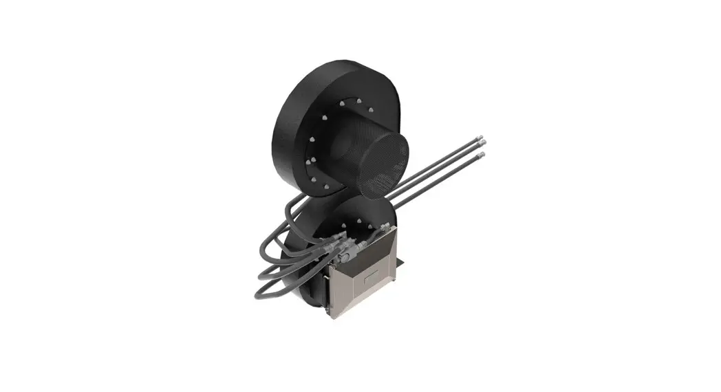
Bourgault Blockage Prevention System
Instruction Manual

Bourgault Blockage Prevention System
| Title | Airguard Blockage Prevention System Upgrade Instructions | RELEASE DATE | 2023-03-01 |
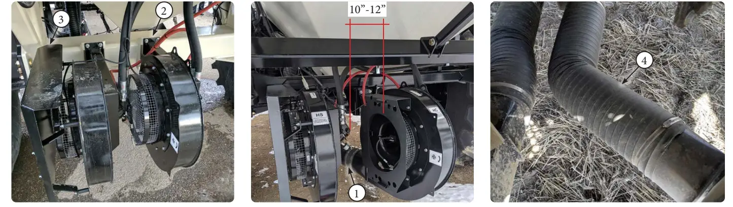
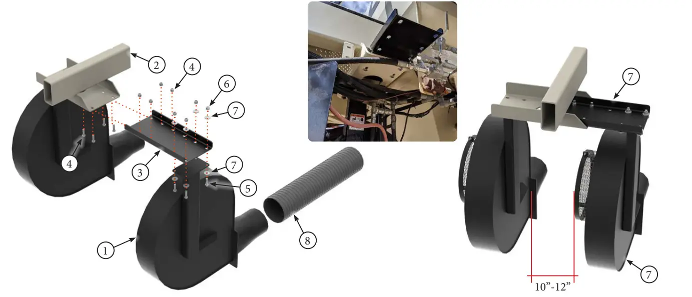
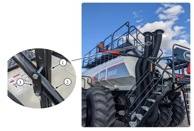
| STEP | 1. For installations on both fans with rear hitch, the fan will need to be shifted over for sufficient room to install the BP System. Disconnect flexible outlet hose (Item 1) from the fan outlet on fan #1 and/or fan #2. Loosen the U-Bolts / Bolts (Item 2) that hold the fan mount bracket to the axle. In some cases the U-Bolts / Bolts may need to be removed completely and reinstalled in the new location. Allow for 10-12” of space between the fan motor and the intake screen of the neighboring fan. A 7” flexible hose extension kit (Item 4) will be required when moving fan over. See pages 3-6 for specific relocation bracket installation inscructions. If installation is only on the out- side fan, remove deflector shield (Item 3) and skip to page 8. | REV # | 1.0 |
| PART KIT # | Varies |
MODEL SPECIFIC CONNECTION WHEN INSTALLING ON
BOTH FANS WITH REAR HITCH: KIT #7923 or 9070
6000 Series Tow Behind
7000 Series Tow Behind
L9000 Series Tow Between
WARNING: Support fan housing from below with a jack or above with hoist to avoid injury and so no extra stress is put on the hydraulic hose connections

| PARTS LIST |
| Item | Part # | Description |
| 1 | — | Flexible Outlet Hose |
| 2 | — | Existing Hardware U-Bolts / Bolts |
| PARTS LIST |
| Item | Part # | Description |
| 3 | — | Deflector Screen |
| 4 | 7923 /or/ 9070 | 7” Flexible Hose |
| Title | Airguard Blockage Prevention System Upgrade Instructions | RELEASE DATE | 2023-03-01 |
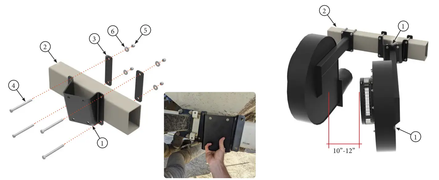
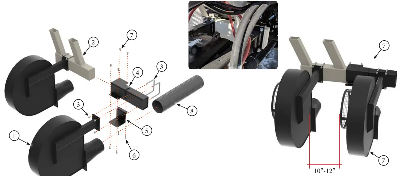
| STEP | 2. For Tow Behind installations with no rear hitch, for specific models as per be- low. Bolt 45 deg bracket (Item 1) to Axle HSS (Item 2) using backing plates (Item 3), 12mm x 130mm Bolts (Item 4) and 12mm Lock Nuts (Item 5) and Flat Washers (Item 6). Unbolt the fan (Item 7) from the Axle HSS (Item 2) and rebolt onto the 45deg bracket (Item 1) using the existing hardware from the Fan. | REV # | 1.0 |
| PART KIT # | Varies |
MODEL SPECIFIC CONNECTION WHEN INSTALLING ON INSIDE
FAN OR ON BOTH FANS AND NO REAR HITCH: KIT #7945
6000series – Tow Behind
7000series – Tow Behind

| PARTS LIST |
| Item | Part # | Description |
| 1 | 7942 | 45deg Bracket |
| 2 | — | Axle HSS |
| 3 | 7943 | Backing Plate |
| 4 | 7863 | Hex Bolt, 12mm x 130mm |
| PARTS LIST |
| Item | Part # | Description |
| 5 | 7669 | Lock Nut, 12mm |
| 6 | 7925 | Flat Washer, 12mm |
| 7 | — | Fan |
| Title | Airguard Blockage Prevention System Upgrade Instructions | RELEASE DATE | 2023-03-01 |
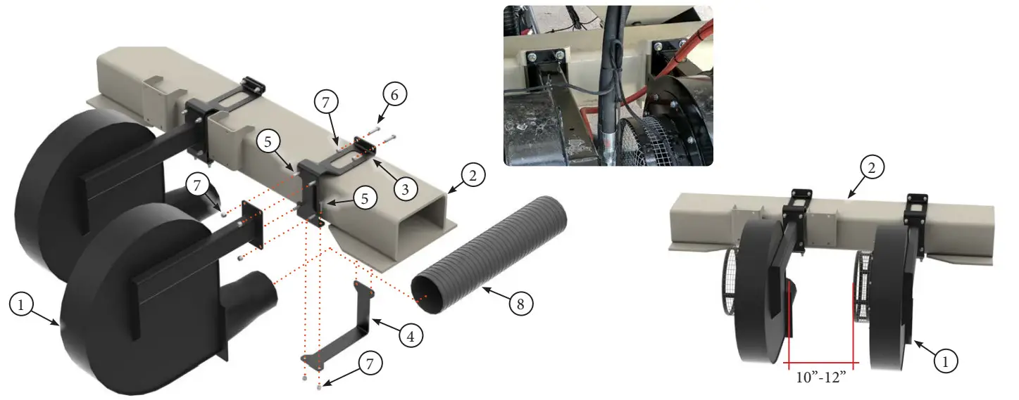
| STEP | 3. For L6000 Series tow between installations, for specific models as per below. Re- move outside fan (Item 1) from Aircart Frame (Item 2). Bolt extension bracket (Item 3) to Aircart Frame (Item 2) using existing hardware (Item 4). Reattach fan (Item 1) to extension bracket (Item 3) using 12mm x 40mm Bolts (Item 5) and 12mm Lock Nuts (Item 6) and Flat Washers (Item 7). A 7” flexible hose extension kit (Item 8) will be required when moving fan over. | REV # | 1.0 |
| PART KIT # | Varies |
MODEL SPECIFIC CONNECTION WHEN INSTALLING ON
OUTSIDE FAN OR ON BOTH FANS: KIT #7923 & 7924
L6000series – Tow Between

| PARTS LIST |
| Item | Part # | Description |
| 1 | — | Fan |
| 2 | — | Aircart Frame |
| 3 | 7922 | Extension Bracket |
| 4 | — | Existing Hardware |
| PARTS LIST |
| Item | Part # | Description |
| 5 | 7671 | Hex Bolt, 12mm x 40mm |
| 6 | 7669 | Lock Nut, 12mm |
| 7 | 7925 | Flat Washer, 12mm |
| 8 | 7923 | 7” Flexible Hose |
| Title | Airguard Blockage Prevention System Upgrade Instructions | RELEASE DATE | 2023-03-01 |
| STEP | 4. For L7000 Series tow between installations, for specific models as per below. Re- move outside fan (Item 1) from Aircart Frame (Item 2). Bolt extension bracket (Item 4) to Aircart Frame (Item 2) using bracket plate (Item 5) with 12mm x 40mm Bolts (Item 6) and 12mm Lock Nuts (Item 7). Reattach fan (Item 1) to extension bracket (Item 4) using existing U-bolts and nuts (Item 3). A 7” flexible hose extension kit (Item 8) will be required when moving fan over. | REV # | 1.0 |
| PART KIT # | Varies |
MODEL SPECIFIC CONNECTION WHEN INSTALLING ON OUTSIDE FAN OR ON BOTH FANS: KIT #7923 & 7850
L7000series – Tow Between

| PARTS LIST |
| Item | Part # | Description |
| 1 | — | Fan |
| 2 | — | Aircart Frame |
| 3 | — | Existing Hardware |
| 4 | 7845 | Extension Bracket |
| PARTS LIST |
| Item | Part # | Description |
| 5 | 7846 | Extension Bracket Plate |
| 6 | 7671 | Hex Bolt, 12mm x 40mm |
| 7 | 7669 | Lock Nut, 12mm |
| 8 | 7923 | 7” Flexible Hose |
| Title | Airguard Blockage Prevention System Upgrade Instructions | RELEASE DATE | 2023-03-01 |
| STEP | 5. For 71300 Series Aircart installations with rear hitch, remove inside fan (Item 1) from axle HSS (Item 2). Bolt fan bracket (Item 3) to Axle HSS (Item 2) using bracket plate (Item 4) with 12mm x 40mm Bolts (Item 5), 12mm x 50mm Bolts (Item 6) and 12mm Lock Nuts (Item 7). Reattach fan (Item 1) to fan bracket (Item 3) using 12mm x 40mm bolts (Item 5) and 12mm Lock Nuts (Item 7). A 7” flexible hose extension kit (Item 8) will be required when moving fan over. When rear hitch is present, both fans must be moved over with fan brackets. | REV # | 1.0 |
| PART KIT # | Varies |
MODEL SPECIFIC CONNECTION WHEN INSTALLING ON INSIDE FAN OR ON BOTH FANS WITH REAR HITCH : KIT #7923 & 7670 71300

| PARTS LIST |
| Item | Part # | Description |
| 1 | — | Fan |
| 2 | — | Aircart Frame |
| 3 | 7665 | Fan Bracket |
| 4 | 7668 | Bracket Plate |
| PARTS LIST |
| Item | Part # | Description |
| 5 | 7672 | Hex Bolt, 12mm x 50mm |
| 6 | 7671 | Hex Bolt, 12mm x 40mm |
| 7 | 7669 | Lock Nut, 12mm |
| 8 | 7923 | 7” Flexible Hose |
| Title | Airguard Blockage Prevention System Upgrade Instructions | RELEASE DATE | 2023-03-01 |
| STEP | 5. For 71300 Series Aircart installations with rear hitch, remove inside fan (Item 1) from axle HSS (Item 2). Bolt fan bracket (Item 3) to Axle HSS (Item 2) using bracket plate (Item 4) with 12mm x 40mm Bolts (Item 5), 12mm x 50mm Bolts (Item 6) and 12mm Lock Nuts (Item 7). Reattach fan (Item 1) to fan bracket (Item 3) using 12mm x 40mm bolts (Item 5) and 12mm Lock Nuts (Item 7). A 7” flexible hose extension kit (Item 8) will be required when moving fan over. When rear hitch is present, both fans must be moved over with fan brackets. | REV # | 1.0 |
| PART KIT # | Varies |
MODEL SPECIFIC CONNECTION WHEN INSTALLING ON INSIDE FAN OR ON BOTH FANS WITH REAR HITCH : KIT #7923 & 7670 71300
| Title | Airguard Blockage Prevention System Upgrade Instructions | RELEASE DATE | 2023-03-01 |
| STEP | 6. For 71300 Series Aircart installations with no rear hitch, remove inside fan (Item 1) from axle HSS (Item 2). Bolt fan bracket plate (Item 3) to Axle HSS (Item 2) using 12mm x 40mm Bolts (Item 4) and 12mm Lock Nuts (Item 5). Mount Angle Bricket (Item 6) to fan bracket plate (Item 3) using 12mm x 40mm Bolts (Item 4), 12mm washers (Item 7) and 12mm Lock Nuts (Item 5). Reattach fan (Item 1) to Angle bracket (Item 6) using existing hardware. | REV # | 1.0 |
| PART KIT # | Varies |
MODEL SPECIFIC CONNECTION: FANS WITH FIXED SCREEN CAGES
HC Fans
HS Fans
HP Fans

| PARTS LIST |
| Item | Part # | Description |
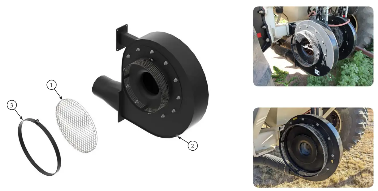
| 1 | — | Fan Screen |
| 2 | — | Fan Housing |
| PARTS LIST |
| Item | Part # | Description |
| 3 | — | Outer Flat Bar Ring |
| Title | Airguard Blockage Prevention System Upgrade Instructions | RELEASE DATE | 2023-03-01 |
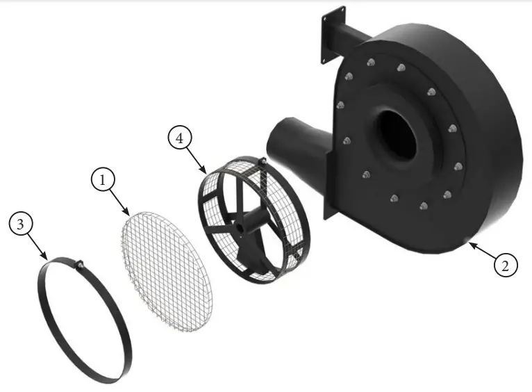
| STEP | 8. For HC, HS and HP Fans with spinner screens, remove existing fan screen (Item 1) from the fan housing (Item 2) by removing the outer flatbar ring (Item 3). Remove existing fan spinner screen assembly parts (Item 4) from the fan housing (Item 2). All spinner parts including center shaft should be removed. Screen material (Item 1) must be cut to free sensor plug. | REV # | 1.0 |
| PART KIT # | Varies |
MODEL SPECIFIC CONNECTION: FANS WITH SPINNER SCREEN CAGES
HC Fans
HS Fans
HP Fans

| PARTS LIST |
| Item | Part # | Description |
| 1 | — | Fan Screen Spinner Assembly |
| 2 | — | Fan Housing |
| PARTS LIST |
| Item | Part # | Description |
| 3 | — | Fan Screen |
| Title | Airguard Blockage Prevention System Upgrade Instructions | RELEASE DATE | 2023-03-01 |
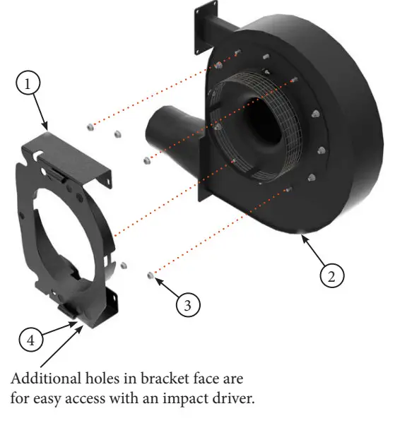
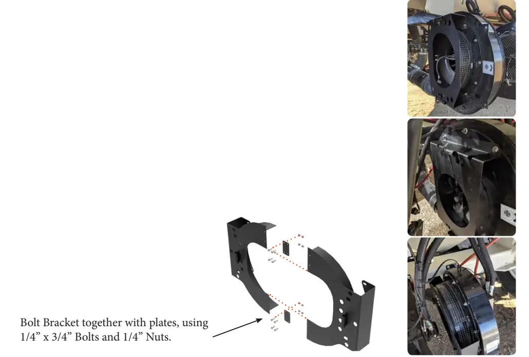
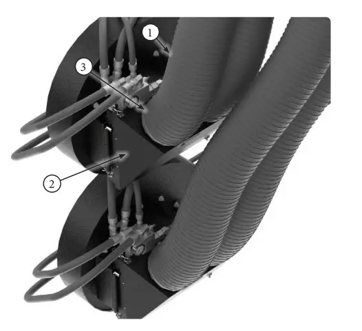
| STEP | 9. Install supplied mounting bracket (Item 1) to fan housing (Item 2) using existing bolts and nuts (Item 3). Angle mount bracket in a position that ensures the supplied hydraulic hoses reach the fan motor. Additional holes in bracket face (Item 4) are for easy access with an impact driver. For Kit #9640, bracket will need to be bolted togeth- er using supplied hardware and plates. Bracket may look different than shown below. | REV # | 1.0 |
| PART KIT # | Varies |

Use Kit # 9510 for the following Mode4000series
5000series
6000series HS & HC Fans
7000series HS & HC Fans
8000series HS & HC Fans
9000series HS & HC Fans
Use Kit # 9610 for the following Models with
screen spinners:
7000series HP Fans
8000series HP Fans
9000series HP Fans
Use Kit # 9640 for the following Models with Screens attached to fan housing:
7000series HP Fans
8000series HP Fans
9000series HP Fans

| PARTS LIST | PARTS LIST |
| Item | Part # | Description | Item | Part # | Description |
| 1 | 7553 / or / 9019 | REM RT Fan Bracket / or / Tsunami Blower Bracket | 3 | — | Existing Hardware |
| 2 | — | REM Fan Housing / or / Tsunami Blower Housing | |
| Title | Airguard Blockage Prevention System Upgrade Instructions | RELEASE DATE | 2023-03-01 |
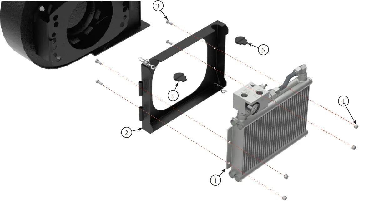
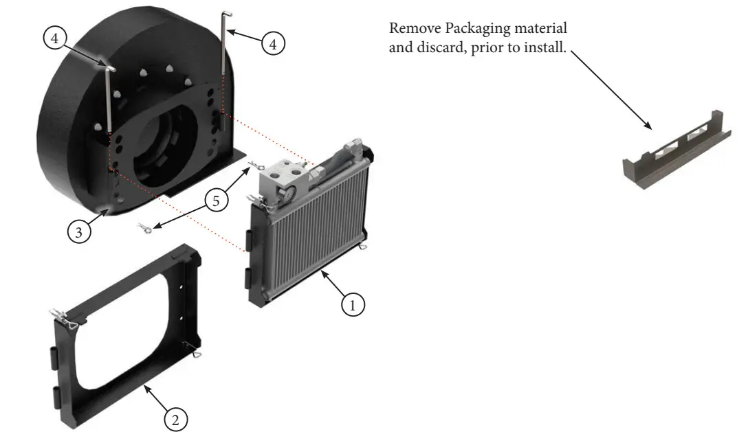
| STEP | 10. Bolt Oil Cooler/Radiator Assembly (Item 1) to BP System Bracket (Item 2) using supplied 10mm x 25mm Bolts (Item 3)and 10mm lock nuts (Item 4). If only installing snorkel kit without Radiator, then install plastic plugs (Item 5) onto BP Sytem Bracket (Item 2). This step of the installation may already be completed at the Airguard facto- ry prior to shipping. | REV # | 1.0 |
| PART KIT # | Varies |

| PARTS LIST |
| Item | Part # | Description |
| 1 | 7996 | Oil Cooler and Manifold Assembly |
| 2 | 7546 | Main BP System Bracket |
| 3 | 7515 | Hex Bolt, 10mm x 25mm Grade 8.8 |
| PARTS LIST |
| Item | Part # | Description |
| 4 | 7516 | Lock Nut, 10mm Grade 8.8 |
| 5 | 7683 | BP System Bracket Plug |
| Title | Airguard Blockage Prevention System Upgrade Instructions | RELEASE DATE | 2023-03-01 |
| STEP | 11. Remove the plastic packaging materials prior to the assembly of these brackets. Mount BP System Main Bracket with Oil Cooler (Item 1) or Main Bracket with Plugs (Item 2) to Fan bracket (Item 3) using supplied pivot pins (Item 4). Secure in place with 3.5mm cotter pins (Item 5). | REV # | 1.0 |
| PART KIT # | Varies |

| PARTS LIST |
| Item | Part # | Description |
| 1 | — | BP System Main Bracket with Oil Cooler |
| 2 | — | BP System Main Bracket with Plugs for Snorkel Only Install |
| 3 | — | REM RT Fan Bracket / or / Tsunami Blower Bracket |
| PARTS LIST |
| Item | Part # | Description |
| 4 | 7502 | Pivot Pin For BP Systems |
| 5 | 7513 | 3.5mm Cotter Pin |
| Title | Airguard Blockage Prevention System Upgrade Instructions | RELEASE DATE | 2023-03-01 |
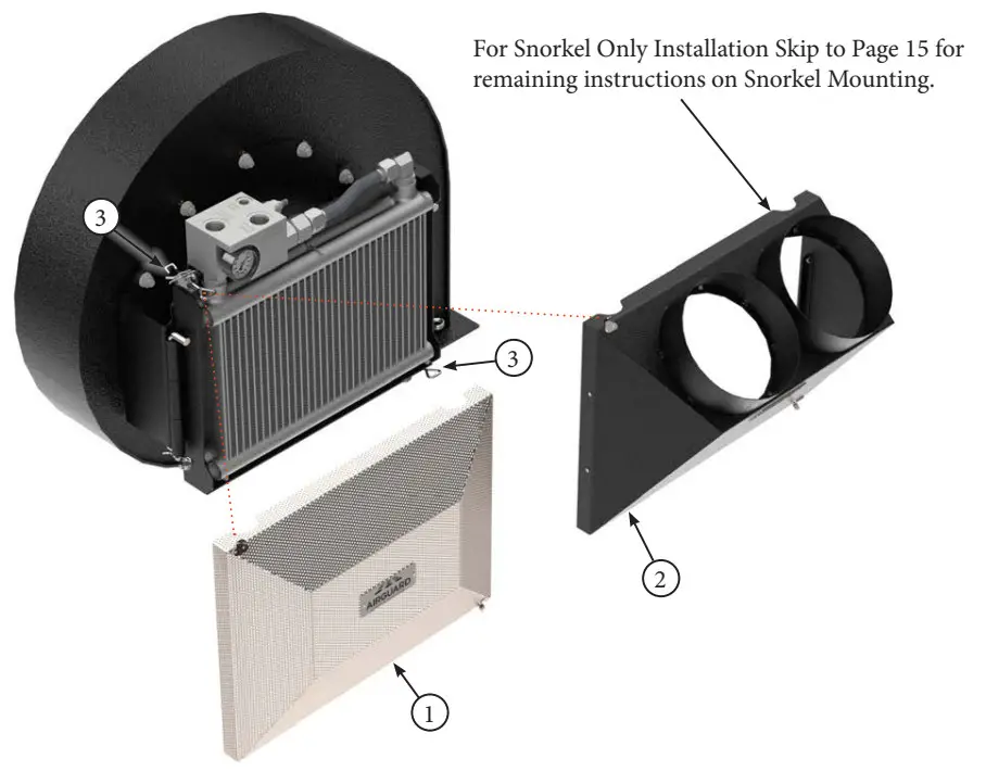
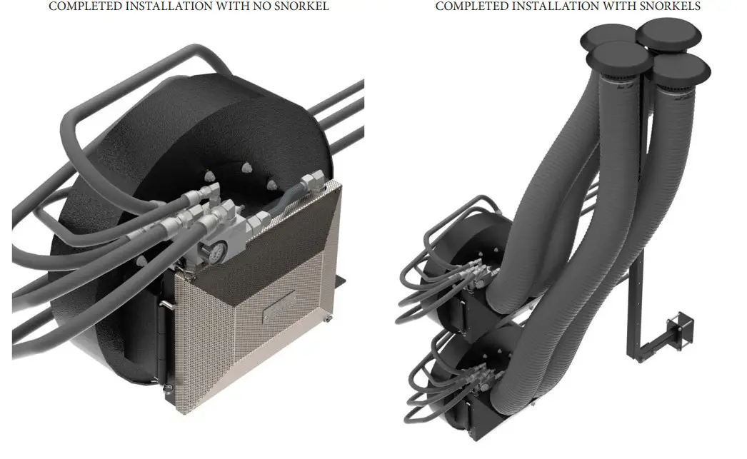
| STEP | 12. Attach Mesh Screen (Item 1) or Snorkel Housing (Item 2) to front of BPS using latches (Item 3). | REV # | 1.0 |
| PART KIT # | Varies |

| PARTS LIST |
| Item | Part # | Description |
| 1 | 7568 | Mesh Screen |
| 2 | 7977 | Snorkel Housing |
| PARTS LIST |
| Item | Part # | Description |
| 3 | — | Overcenter Latch |
| Title | Airguard Blockage Prevention System Upgrade Instructions | RELEASE DATE | 2023-03-01 |
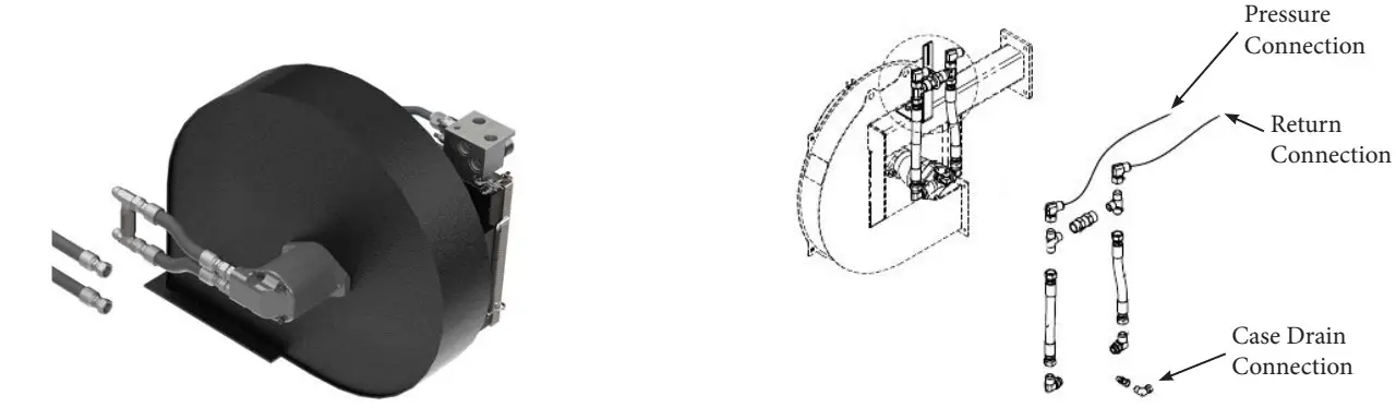
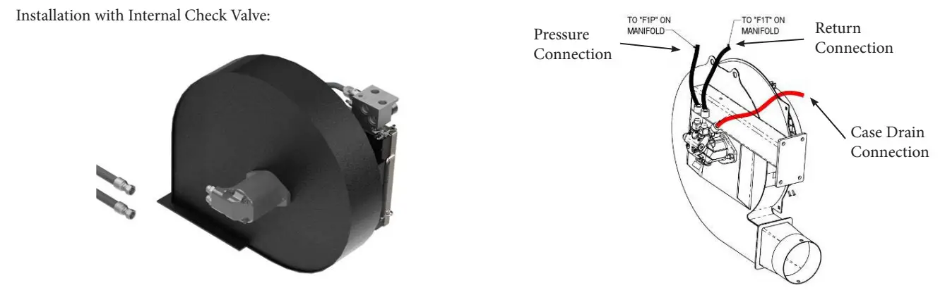
| STEP | 13. Identify the model of aircart that the Airguard Blockage Prevention System is being installed on. For models with external check valves, the connections must be made on the tractor side of the hydraulic circuit as shown below. | REV # | 1.0 |
| PART KIT # | Varies |
Installation with External Check Valve:


| Title | Airguard Blockage Prevention System Upgrade Instructions | RELEASE DATE | 2023-03-01 |
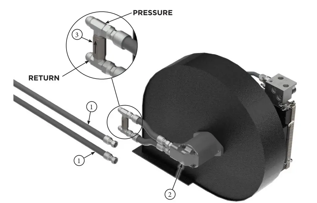
| STEP | 14. Remove factory hoses (Item 1) from side of fan motor (Item 2). Remove the hoses (Item 1) on the tractor side of the external check valve, as shown below. Identify which hose is the pressure side of the circuit. The external check valve will have a di- rectional arrow that always points to the pressure side. If you do not have an external check valve you will attach directly to the fan motor. | REV # | 1.0 |
| PART KIT # | Varies |

| PARTS LIST |
| Item | Part # | Description |
| 1 | — | Existing Hose from Tractor to Fan Motor |
| 2 | — | Hydraulic Motor |
| PARTS LIST |
| Item | Part # | Description |
| 3 | — | External Check Valve |
| Title | Airguard Blockage Prevention System Upgrade Instructions | RELEASE DATE | 2023-03-01 |
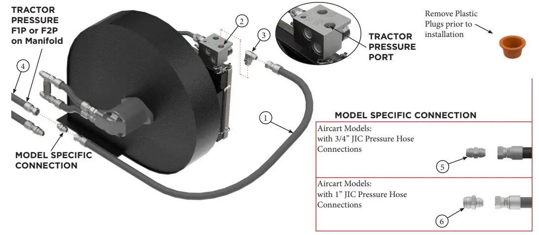
| STEP | 15. Hoses may be routed to suit your specific aircart installation. Install supplied 3/4” hydraulic hose (Item 1) to the “TRACTOR PRESSURE” port of the radiator block (Item 2), using adapter (Item 3) to make the connection. Use model specific connec- tion as per instuctions below to attach the other end of the hose to the factory pres- sure line (Item 4) that was removed from the fan motor. | REV # | 1.0 |
| PART KIT # | Varies |

| PARTS LIST |
| Item | Part # | Description |
| 1 | 9016 | BPS 3/4” Hydraulic Hose – 60” |
| 2 | — | “TRACTOR PRESSURE” Port – BP System Manifold |
| 3 | 7506 | Fiting – Elbow – 3/4” JIC Male – 3/4” ORB Male |
| PARTS LIST |
| Item | Part # | Description |
| 4 | — | Tractor Supply (Pressure) Hydraulic Hose |
| 5 | 7538 | Fitting – Straight – 3/4” JIC M – 3/4” JIC M |
| 6 | 7237 | Fitting – Straight – 1” JIC M – 3/4” JIC M |
| Title | Airguard Blockage Prevention System Upgrade Instructions | RELEASE DATE | 2023-03-01 |
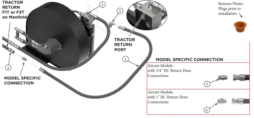
| STEP | 16. Install supplied 3/4” hydraulic hose (Item 1) to the “TRACTOR RETURN” port of the radiator block (Item 2) using adapter (Item 3). Use model specific connection as per instuctions below to attach the other end of the hose to the factory pressure line (Item 4) that was removed from the fan motor. | REV # | 1.0 |
| PART KIT # | Varies |

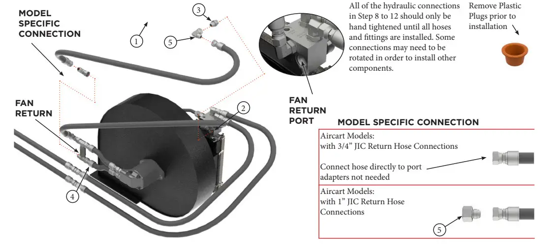
All of the hydraulic connections in Step 8 to 12 should only be hand tightened until all hoses and fittings are installed. Some connections may need to be rotated in order to install other components
| PARTS LIST |
| Item | Part # | Description |
| 1 | 9016 | BPS 3/4” Hydraulic Hose – 60” |
| 2 | — | “TRACTOR RETURN” Port – BP System Manifold |
| 3 | 7506 | Fiting – Elbow – 3/4” JIC Male – 3/4” ORB Male |
| PARTS LIST |
| Item | Part # | Description |
| 4 | — | Tractor Return Hydraulic Hose |
| 5 | 7538 | Fitting – Straight – 3/4” JIC M – 3/4” JIC M |
| 6 | 7237 | Fitting – Straight – 1” JIC M – 3/4” JIC M |
| Title | Airguard Blockage Prevention System Upgrade Instructions | RELEASE DATE | 2023-03-01 |
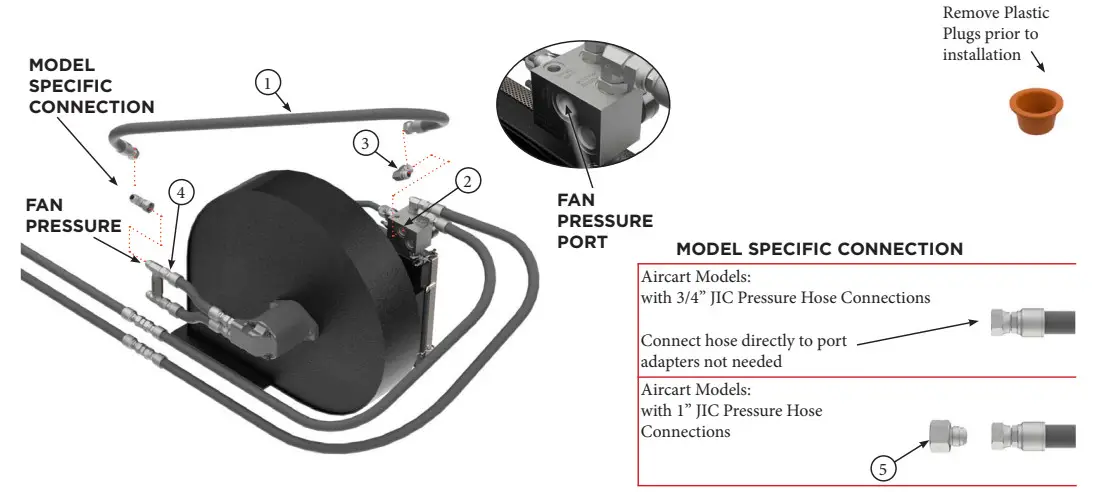
| STEP | 17. Install supplied 3/4” hydraulic hose (Item 1) to the “FAN PRESSURE” port of the radiator block (Item 2) using adapter (Item 3). Use model specific connection as per instuctions below to attach the other end of the hose to the factory fan pressure line/ port (Item 4) coming from the fan motor. | REV # | 1.0 |
| PART KIT # | Varies |

| PARTS LIST |
| Item | Part # | Description |
| 1 | 9016 | BPS 3/4” Hydraulic Hose – 60” |
| 2 | — | “FAN PRESSURE” Port – BP System Manifold |
| 3 | 7506 | Fiting – Elbow – 3/4” JIC Male – 3/4” ORB Male |
| PARTS LIST |
| Item | Part # | Description |
| 4 | — | Fan Supply (Pressure) Hydraulic Hose |
| 5 | 7238 | Fitting – Straight – 1” JIC F – 3/4” JIC M |
| Title | Airguard Blockage Prevention System Upgrade Instructions | RELEASE DATE | 2023-03-01 |
| STEP | 18. Install supplied 3/4” hydraulic hose (Item 1) to the “FAN RETURN” port of the radiator block (Item 2) using adapters (Item 3 & 5). Use model specific connection as per instuctions below to attach the other end of the hose to the factory fan return line/ port (Item 4) coming from the fan motor. | REV # | 1.0 |
| PART KIT # | Varies |

| PARTS LISTC |
| Item | Part # | Description |
| 4 | — | Fan Return Hydraulic Hose |
| 5 | 7238 | Fitting – Straight – 1” JIC F – 3/4” JIC M |
| Title | Airguard Blockage Prevention System Upgrade Instructions | RELEASE DATE | 2023-03-01 |
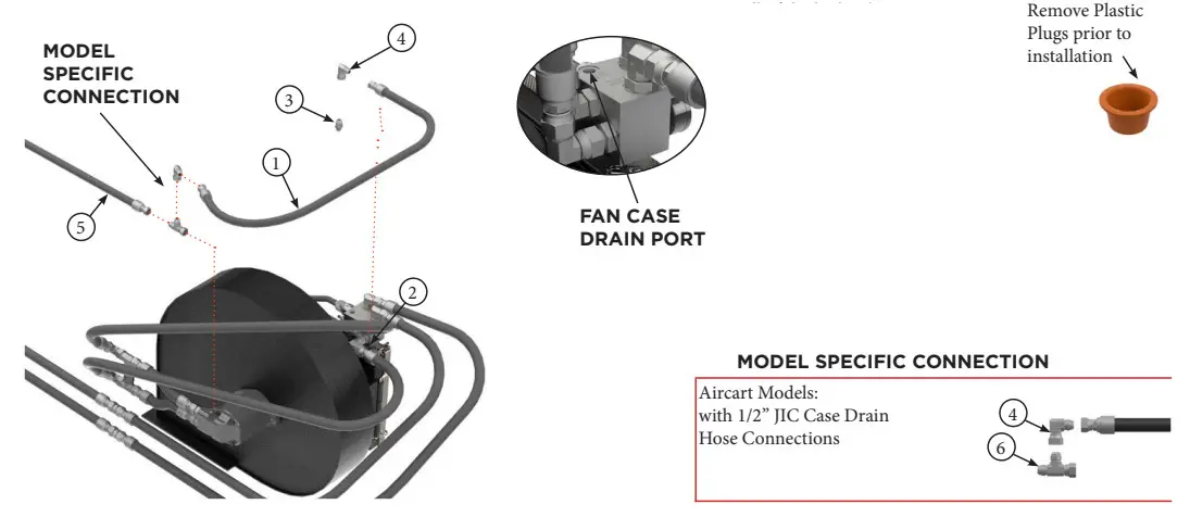
| STEP | 19. Install supplied 1/2” hydraulic hose (Item 1) to the “CASE DRAIN” port of the radiator block (Item 2) using adapters (Item 3 & 4). and to the fan motor case drain line (Item 5). Use model specific connection as per instuctions below to attach the other end of the hose to the factory fan case drain line/port (Item 5) coming from the fan motor. | REV # | 1.0 |
| PART KIT # | Varies |

| PARTS LIST |
| Item | Part # | Description |
| 1 | 9016 | BPS 3/4” Hydraulic Hose – 60” |
| 2 | — | “FAN CASE DRAIN” Port – BP System Manifold |
| 3 | 7264 | Fitting – Straight – 1/2” JIC Male – 3/8” ORB Male |
| PARTS LIST |
| Item | Part # | Description |
| 4 | 7686 | Fiting – Elbow – 1/2” JIC M – 1/2” JIC F |
| 5 | — | Fan Case Drain Hydraulic Hose |
| 6 | 7263 | Fitting – Tee – 1/2” JIC M – M – F |
| Title | Airguard Blockage Prevention System Upgrade Instructions | RELEASE DATE | 2023-03-01 |
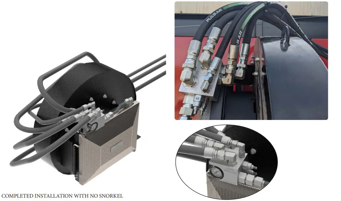
| STEP | 20. Complete the hydraulic installation by ensuring that all connections made in Step 8 to 12 are tightened. Position/Routing of hydraulic hoses may vary to suit each spe- cific machine installation. Zip tie hoses to reduce wear and ensure tidy installation. | REV # | 1.0 |
| PART KIT # | Varies |

| Title | Airguard Blockage Prevention System Upgrade Instructions | RELEASE DATE | 2023-03-01 |
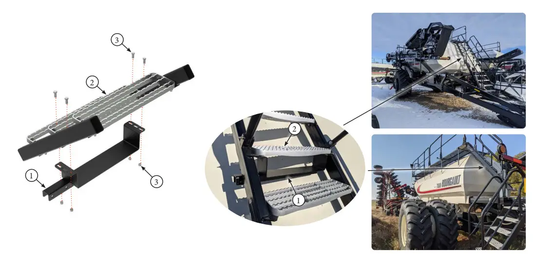
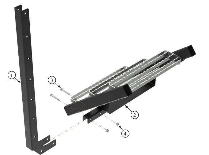
| STEP | 21. For snorkel mount on specific aircarts as per below. Install the bracket (Item 1) onto the Aircart Stair Tread (Item 2) using existing stair tread hardware (Item 3). | REV # | 1.0 |
| PART KIT # | Varies |
MODEL SPECIFIC CONNECTION – KIT 9000:
7550, 7700, 7950, 71300 L7550, L7701,
L7800 8350, 8450, 8550 L8350, L8450, L8550 9650, 9950, 91300 L9650, L9950

| PARTS LIST |
| Item | Part # | Description |
| 1 | 9001 | Bourgault Snorkel Mount Bracket |
| 2 | — | Stair Tread |
| PARTS LIST |
| Item | Part # | Description |
| 3 | — | Existing stair tread hardware |
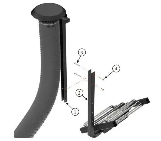
| Title | Airguard Blockage Prevention System Upgrade Instructions | RELEASE DATE | 2023-03-01 |
| STEP | 22. Mount Outer Vertical Channel (Item 1) to Bracket (Item 2) using supplied 12mm x 80mm Bolts (Item 3) and 12mm lock nuts (Item 4). | REV # | 1.0 |
| PART KIT # | Varies |
MODEL SPECIFIC CONNECTION – KIT 9000:
7550, 7700, 7950, 71300 L7550,
L7701, L7800 8350, 8450,
8550 L8350, L8450,
L8550 9650, 9950, 91300 L9650, L9950

| PARTS LIST |
| Item | Part # | Description |
| 1 | 7865 | Outer Vertical Channel |
| 2 | 9001 | Bourgault Snorkel Mount Bracket |
| PARTS LIST |
| Item | Part # | Description |
| 3 | 7859 | Hex Bolt, 12mm x 80mm |
| 4 | 7669 | Lock Nut, 12mm |
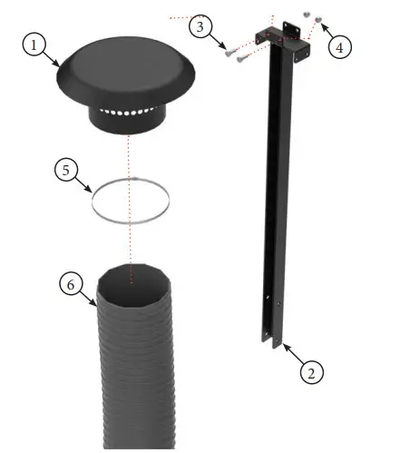
| Title | Airguard Blockage Prevention System Upgrade Instructions | RELEASE DATE | 2023-03-01 |
| STEP | 23. Attach air intakes (Item 1) to upper vertical channel (Item 2) using supplied 10mm x 25mm Bolts (Item 3) and 10mm lock nuts (Item 4). A maximum of 4 intakes can be mounted. Use bridge clamp (Item 5) to attach 8” flex hose (Item 6) to air intake (Item 1). | REV # | 1.0 |
| PART KIT # | Varies |
MODEL SPECIFIC CONNECTION – KIT 9000: 7550, 7700, 7950, 71300 L7550, L7701, L7800 L8350, L8450, L8550 9650, 9950, 91300 L9650, L9950

| PARTS LIST |
| Item | Part # | Description |
| 1 | 7576 | Air Intake Bracket |
| 2 | 7868 | Upper Vertical Channel |
| 3 | 7515 | Hex Bolt, 10mm x 25mm |
| PARTS LIST |
| Item | Part # | Description |
| 4 | 7516 | Lock Nut, 10mm |
| 5 | 7578 | Bridge Clamp, 8” |
| 6 | 7572 | Flexible Snorkel Hose – 8” |
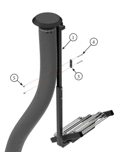
| Title | Airguard Blockage Prevention System Upgrade Instructions | RELEASE DATE | 2023-03-01 |
| STEP | 24. Determine desired height of air intakes and secure upper vertical channel (Item 1) to lower vertical channel (Item 2) at that location. Use supplied 12mm x 80mm Bolts (Item 3) and 12mm lock nuts (Item 4). | REV # | 1.0 |
| PART KIT # | Varies |
MODEL SPECIFIC CONNECTION – KIT 9000: 7550, 7700, 7950, 71300, L7550, L7701, L7800 8350, 8450, 8550 L8350, L8450, L8550 9650, 9950, 91300 L9650, L9950

| PARTS LIST |
| Item | Part # | Description |
| 1 | 7868 | Upper Vertical Channel |
| 2 | 7865 | Outer Vertical Channel |
| PARTS LIST |
| Item | Part # | Description |
| 3 | 7859 | Hex Bolt, 12mm x 80mm |
| 4 | 7669 | Lock Nut, 12mm |
| Title | Airguard Blockage Prevention System Upgrade Instructions | RELEASE DATE | 2023-03-01 |
| STEP | 25. Attach stabilizer bracket (Item 1) to catwalk railing (Item 2) using railing mount plate (Item 3) and supplied 12mm x 80mm Bolts (Item 4) and 12mm lock nuts (Item 5). | REV # | 1.0 |
| PART KIT # | Varies |

MODEL SPECIFIC CONNECTION – KIT 9000: 7550, 7700, 7950, 71300, L7550, L7701, L7800 8350, 8450, 8550 L8350, L8450, L8550 9650, 9950, 91300 L9650, L9950

| PARTS LIST |
| Item | Part # | Description |
| 1 | 7868 | Upper Vertical Channel |
| 2 | — | Catwalk Railing |
| 3 | 7959 | Railing Mount Plate |
| PARTS LIST |
| Item | Part # | Description |
| 4 | 7859 | Hex Bolt, 12mm x 80mm |
| 5 | 7669 | Lock Nut, 12mm |
| Title | Airguard Blockage Prevention System Upgrade Instructions | RELEASE DATE | 2023-03-01 |
| STEP | 26. Attach 8” flex hose (Item 1) to snorkel housing (Item 2) using bridge clamp (Item 3). Zip tie 8” flex hoses to reduce wear and ensure tidy installation. | REV # | 1.0 |
| PART KIT # | Varies |

| PARTS LIST |
| Item | Part # | Description |
| 1 | 7977 | Snorkel Housing |
| 2 | 7578 | Bridge Clamp, 8” |
| PARTS LIST |
| Item | Part # | Description |
| 3 | 7572 | Flexible Snorkel Hose – 8” |
| Title | Airguard Blockage Prevention System Upgrade Instructions | RELEASE DATE | 2023-03-01 |
| STEP | Installation is Completed. Ensure all hydraulic connections and bolts are tightened. | REV # | 1.0 |
| PART KIT # | Varies |

Release Date: 2023-03-01
Part Kit #VARIES – Rev 1.0 – AIRGUARD – Blockage Prevention System