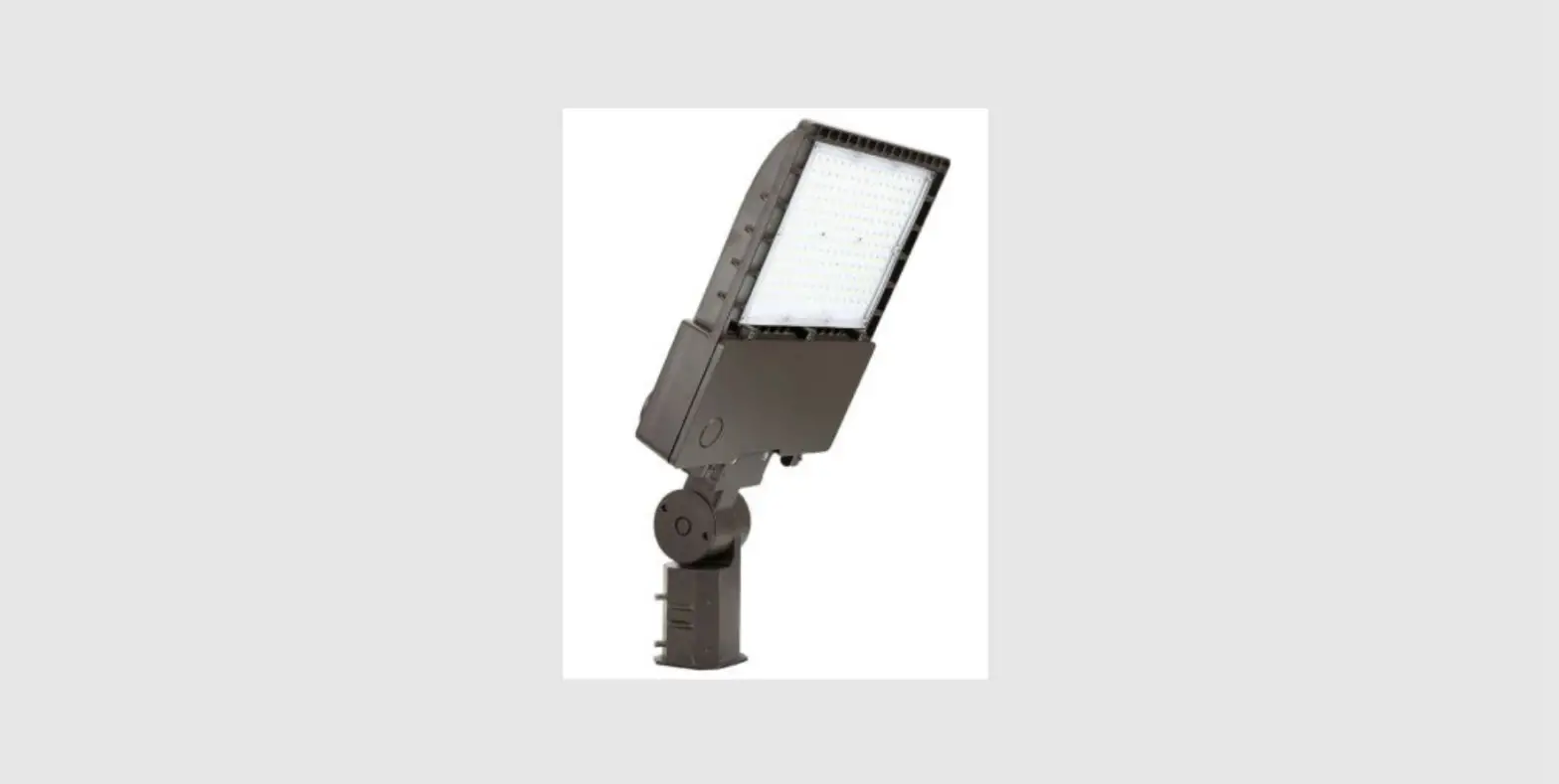
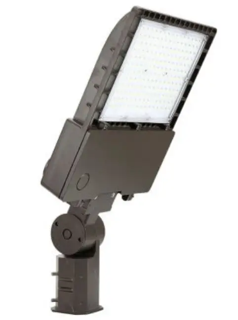
GKOLED GKOAL04150W27V40KDT3-SPAL04DA LED Area Light
WARNING
PLEASE READ ALL INSTRUCTIONS BEFORE ATTEMPTING INSTALLATION
- To prevent personal injury or product damage only licensed electricians should install.
- To avoid electric shock or component damage disconnect power before attempting installation or servicing.
- This product must be installed in accordance with the national electric code (NEC) and all applicable federal, state and local electric codes and safety standards.
- Disconnect product and allow cooling prior to servicing.
- Any alteration or modification of this product is expressly forbidden as it may cause serious personal injury, death, property damage and/or product malfunction.
- To prevent product malfunction and/or electrical shock this product must be properly grounded.
- This luminaire is designed to operate in ambient temperatures ranging from -4D’F to 113’F (-4D’C to 45’C) and to be horizontally mounted with the LEDs facing down.
- This product must be installed in accordance with the applicable installation code by a Person familiar with the construction and operation of the product and
the hazards involved. - MIN 167’F (75’C) SUPPLY CONDUCTORS
- CONSULT A QUALIFIED ELECTRICIAN TO ENSURE CORRECT BRANCH CIRCUIT CONDUCTOR
- CAUTION – RISK OF FIRE
- This product is not suitable for several special environments, such as places with corrosive gas liquids or high pressure water vapor.
Installation
Square/Round Pole (Figure 1) 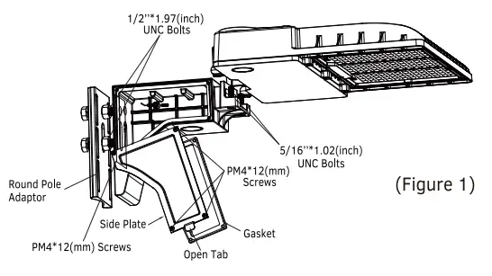
- Loosen the 4 pcs. PM4*12mm screws and remove the side plate and rubber gasket from the mounting bracket. Please skip to Step 3 if using a Square Pole Mount.
- If using the Round Pole Adaptor, place the adaptor between the arm and
the pole, with the radius side of adaptor towards pole. - Pass the 2 pcs. 1/2″*1.97″ hex bolts from inside of the pole through Round Pole Adaptor (if using it) and the back of the arm, slide on flat washers followed by M 14 spring washers, tighten 1 /2″ nuts to 320 in-lbs (36 N•m).
- Feed the lead from the arm into the pole and make wiring connections inside the pole as per the wiring diagram on the next page.
- Feed the fixture cord into the arm. Align threaded mounting holes of fixture with exposed ends of 2 pcs. 5/16″*1.02″ hexagon socket bolts, slide the fixture into the groove of the arm, tighten the bolts to 132 in-lbs (15 N•m).
- Inside the arm, make wiring connections between the lead from the fixture and lead from the arm as per the wiring diagram on the next page.
- Reinstall the side plate and rubber gasket, tightening the screws to 30 in-lbs (3.5 N•m). The gasket should be sitting flush between the side plate
and mount, creating a tight seal around the edges.
Installation with Round Pole Adaptor 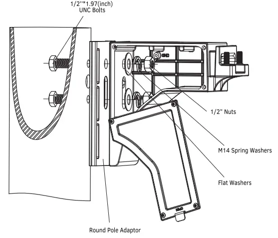
Installation without Round Pole Adaptor 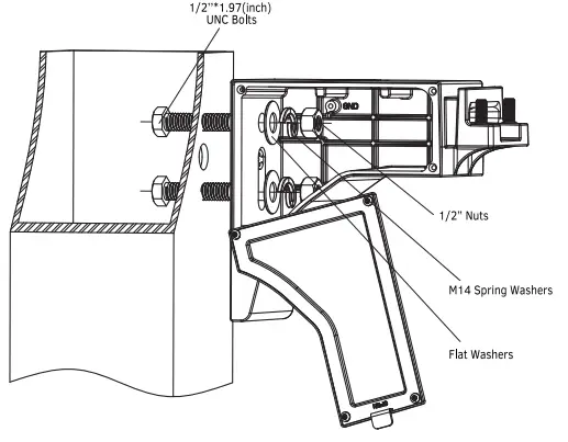
Slipfitter (Figure 2) 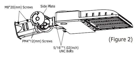
- Remove the side plate by loosening the 2 pcs. PM4*12mm screws.
- Loosen the HM10*25mm hex bolt, but do not unscrew it. Replace the side plate, tilt the adjustable arm to the desired angle and tighten the
HM10*25mm hex bolt to 240 in-lbs (27 N·m) to lock the adjustable arm in place. Tighten the 2pcs. PM4*12mm screws to 30 in-lbs (3.5 N•m) to fix the side plate. - Feed the fixture wire through the center hole of the adjustable arm and the lower fitter, make wiring connections per the wiring diagram below.
- Align threaded mounting holes of fixture with exposed ends of 2 pcs.
5/16″*1.02″ hexagon socket bolts, slide the fixture into the groove of the arm, tighten the bolts to 132 in-lbs (15 N•m). - Slip lower fitter over 2 – 3/8″ (60 mm) o.d. heavy wall pipe or tenon and securely tighten 4pcs. M8*20mm hexagon head set screws to 132 in-lbs (15 N•m). Make sure not to pinch any leads.
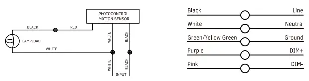
WIRING DIAGRAM 
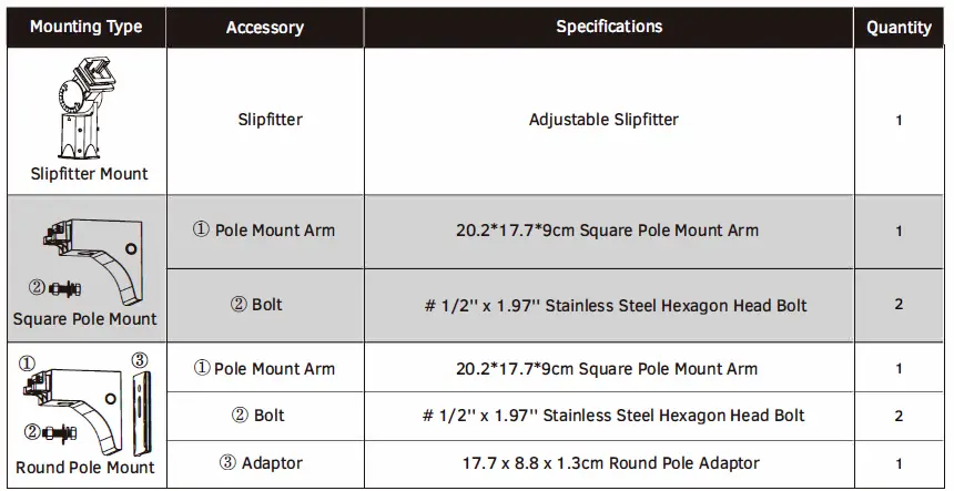
ACCESSORY LIST
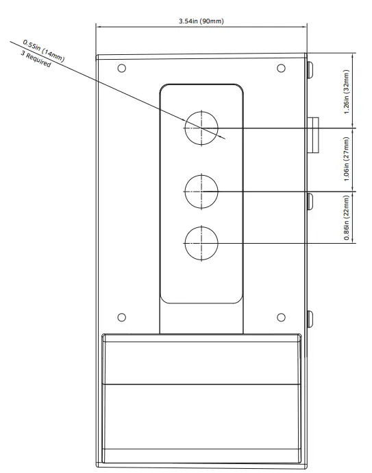
SQUARE/ROUND POLE DRILLING TEMPLATE
(Rendering not to scale)