GMLighting ELECTRONIC LED DRIVER Installation Guide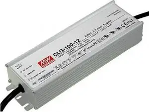
GENERAL
This LED driver is to be installed Indoor in accordance with Article 450 of the National Electric code (N.E.C.) . The LED driver must be installed in a well-ventilated area free from explosive gases and vapors. Proper operation requires the free flow of air. Only a qualified electrician should install this hardwired LED driver.
PRECAUTIONS BEFORE INSTALLING
Check the label and ensure the LED driver has the proper input voltage, output voltage and wattage for the job. Check the wire color to ensure they match the wiring diagram on this instruction sheet.
MOUNTING
Select a suitable location capable of supporting the weight of the LED driver.
INPUT CONNECTIONS/GROUNDING
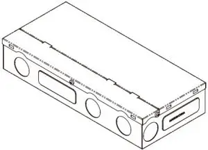
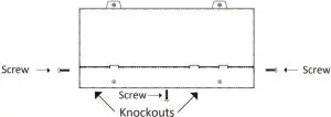
Remove the wiring compartment knockouts and install strain reliefs.
With power turned off, route the input wires through a strain relief.
Plug Neutral, Live and grounding wires into the each terminal of white, black and green wires from LED driver respectively.
The LED driver MUST be grounded in accordance with the N.E.C.
OUTPUT CONNECTIONS
Bring the lamp wires through the open knockout.
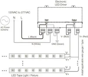
Single-channel output models:
Plug the LED positve (+) wire into terminal of red wire from LED driver.
Plug the LED negatve (–) wire into terminal of blue wire from LED driver.
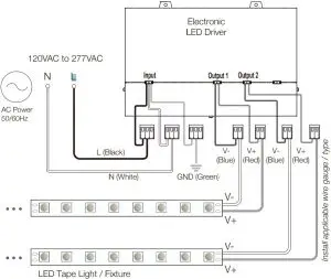
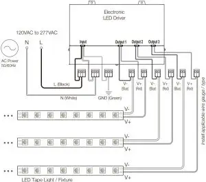
Multi-channel output models:
Refer to their unit label and specification for each output connection.Please note interconnection of outputs are not permitted.
QUICK SPECS
| Input Voltage | See Product Label |
| Output Voltage | |
| Maximum Load | |
| Operating Temp | -40° ~ 140°F (-40° ~ 60°C) |
| Environment | Dry and Damp Location / Indoor |
INPUT VOLTAGE NOTE!
The input voltage: 120VAC to 277VAC
ENSURE to power the driver with the correct voltage!
INSTALLATION
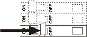
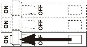
TURNING OFF POWER
![]() WARNING: Electric Shock Hazard. May result in serious injury or death.
WARNING: Electric Shock Hazard. May result in serious injury or death.
Turn power OFF at circuit breaker prior to installation.
INSTALL COMPONENTS
- LED Driver

- Fixture

REMOVE WIRING COVER. WIRE DRIVER.
Pop off cover to access wiring compartment.
Remove knockouts with hammer and punch.
Attach load and control. Only use copper wiring. Refer to ‘System Diagrams’, and installation guides.
TURN POWER ON AT CIRCUIT BREAKER
Install Additional Components, Verify Connections and turn main power ON at breaker.
SYSTEM WORKING IMPROPERLY?
Turn power OFF at circuit breaker and verify all connections. Review WIRING and TROUBLESHOOTING
WIRING DIAGRAMS
The following diagrams are provided as example system designs. Install in accordance with national and local electrical code regulations.
- SINGLE CHANNEL DIAGRAM

- TWO-CHANNEL DIAGRAM

- THREE-CHANNEL DIAGRAM

VOLTAGE DROP CHART
This chart indicates dc voltage at the beginning of your LED Linear Lighting Run.
Voltage Drop Chart for 24VDC
Wire Size | Distance | Load current in amp (per run) | ||||
1.25AMP | 2.5AMP | 4.0AMP | 4.16AMP | 5.0AMP | ||
18AWG | 10ft | 23.84 | 2368 | 23.49 | 23.47 | 23.36 |
| 25ft | 23.60 | 23.20 | 22.72 | 22.67 | 22.40 | |
50ft | 23.20 | 22.40 | 23.49 | 23.47 | 23.36 | |
| 100ft | 22.40 | 20.80 | 18.88 | 18.67 | 17.60 | |
200f | 20.80 | 17.60 | 13.76 | 13.35 | 11.20 | |
| 14AWG | 10ft | 23.94 | 23.87 | 23.80 | 23.79 | 23.75 |
25ft | 23.84 | 23.68 | 23.49 | 23.47 | 23.37 | |
| 50ft | 23.68 | 23.37 | 22.99 | 22.95 | 22.74 | |
100ft | 23.37 | 22.74 | 21.98 | 21.90 | 21.47 | |
| 200f | 22.74 | 21.47 | 19.96 | 19.80 | 18.95 | |
12AWG | 10ft | 23.96 | 23.92 | 23.87 | 23.87 | 23.84 |
25ft | 23.90 | 23.80 | 23.68 | 23.67 | 23.60 | |
50ft | 23.80 | 23.60 | 23.36 | 23.34 | 23.21 | |
| 100ft | 23.60 | 23.21 | 22.73 | 22.68 | 22.41 | |
| 200f | 23.21 | 22.41 | 21.46 | 21.36 | 20.82 | |
10AWG | 10ft | 23.98 | 23.95 | 23.92 | 23.92 | 23.90 |
25ft | 23.94 | 23.88 | 23.80 | 23.79 | 23.75 | |
50ft | 23.88 | 23.75 | 23.60 | 23.58 | 23.50 | |
| 100ft | 23.75 | 23.50 | 23.20 | 23.17 | 23.00 | |
| 200f | 23.50 | 23.00 | 22.40 | 22.34 | 22.00 | |
Note: The results are based on an estimation under normal conditions.
TROUBLESHOOTING
Prior to troubleshooting, ensure all items are a compatible system and main power is turned ON.
| Fixture does not illuminate |
|
| Fixture is flashing or flickering |
|
| Installation Trips Main Breaker |
|