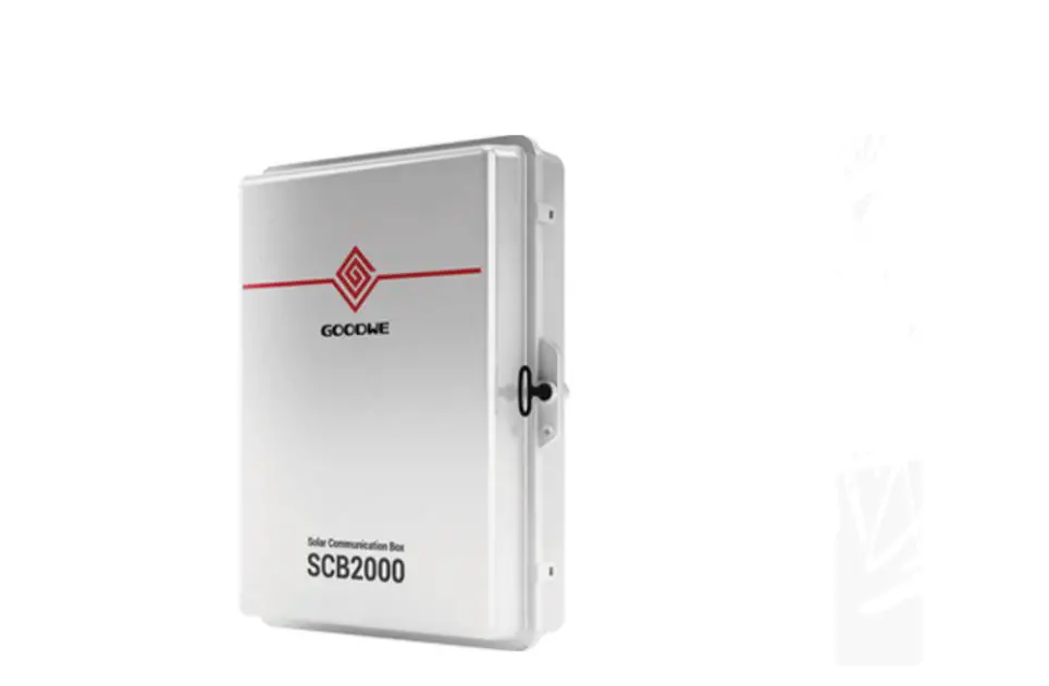
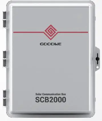
GoodWe SCB2000 Solar Communication Box
Symbols
 Caution! – Failure to observe a warning indicated in this manual may result in minor or moderate injury.
 Danger of high voltoge and electric shock.
 Product should not be disposed as normal household waste.
  CE Mark
  Keep Dry The package/product must be protected from excessive humidity andmust accordingly be stored under cover.
  Components of the product can be recycled.
  This side up – The package must always be transported, handled and stored in such a way that the arrows always point upwards.
  No more than six (6) identical packages be stacked on each other.
  The package/product should be handled carefully and never be tipped over or slung.
Safety and Warning
SCB2000 of GoodWe Technologies Co. Ltd.(hereinafter referred to as GoodWe) has been designed and tested strictly according to the international safety regulation.As electrical and electric equipment,Safety Regulation shall be followed during installation and maintenance.lmproper operation may bring severe damage to the operator,the third party and other properties.Installation.maintenance of SCB2000 must be performed by qualified personnel.in compliance with local electrical standards.regulations and the requirements of local power authorities. To avoid electric shock,make sure the connection between SCB2000 and AC output of inverter.SCB2000 and Grid, is disconnected before performing any installation or maintenance. When in operation,users should not touch any of the electrical parts of SCB2000,like internal components. cables, to avoid electic shock. All electrical installations must comply with local electrical standards and obtain permission from local power authorities before SCB2000 can be connected to the grid by professionals. Before replacing any internal components of SCB2000, the connection between the inverter and SCB2000,the power grid and SCB2000 must be disconnected, and the newly replaced components must meet the requirements of SCB2000.Otherwise,GoodWe will not assume the responsibility and quality assurance for the personal harm. Make sure that the AC input voltage and input current match the rated voltage and current of SCB2000, otherwise the components will be damaged or cannot work properly.and GoodWe will not assume the responsibility and quality assurance for this case. There are lightning protection modules inside.Make sure to connect the internal PE with the ground when intlling SCB2000. When in operation, do not plug or unplug cables of SCB2000. SCB2000 must be Installed out of reach of children. Appropriate antistatic measures should be taken.
Mounting
Mounting Instruction
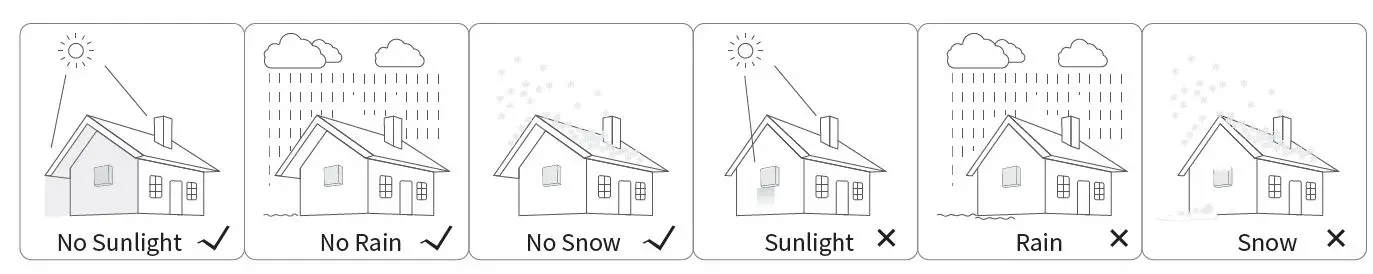
- SCB2000 must be installed where there is no significant shaking, shock vibration and no rain or snow.
- SCB2000 shall be installed at eye level for easy operation and maintenance.
- SCB2000 shoud not be installed near inflammable and explosive items.Any strong electro-magnetic equipment should bekept away from installation site.
- SCB2000 shall be installed at a location free from explosive hazardous media and free from gas and dust sufficient to corrode metals and destroy insulation.
- SCB2000 parameters and warning signs must be clearly visible after installation.
- SCB2000 should be installed without sunshine, rain and snow.
Overview and Packaging
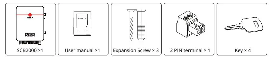
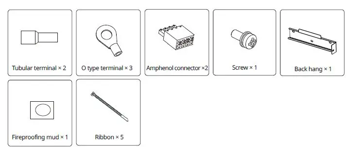
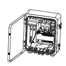
After opening the package,confirm if it is consitent with specification of SCB2000 you purchased.
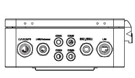
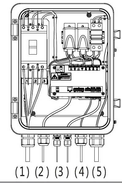
SCB2000 Overview
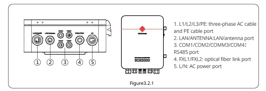
- L1/L2/L3/PE: three-phase AC cable and PE cable port
- LAN/ANTENNA:LAN/antenna port
- COM1/COM2/COMM3/COM4:RS485 port
- FXL1/FXL2: optical fiber link port
- L/N: AC power port
Package
SCB2000 lnstallation
Selecting the installation location
The following must be considered when selecting the best location for an SCB2000.
- The mount and installation method must be appropriate for the SCB2000’s weight and dimensions.
- lnstall on a sturdy surface.
- The installation location must be well ventilated.
- SCB2000 can be placed horizontally or installed vertically.
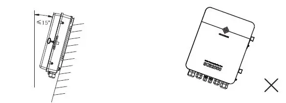
- The SCB2000 must be installed vertical or with a backward tilt less 15°.
- No sidwways tilt is allowed.The connection area must point downwards.
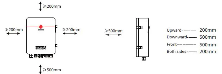
To allow dissipation of heat,and for convenience of dismantling,clearances around the SCB2000 must be no less than the values.
Mounting Procedure
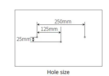
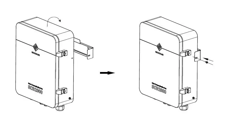
Drill holes on the wall,8mm in diameter and 45mm deep. Fix the wall mounting bracket on the wall with expansion bolts in accessory bag.
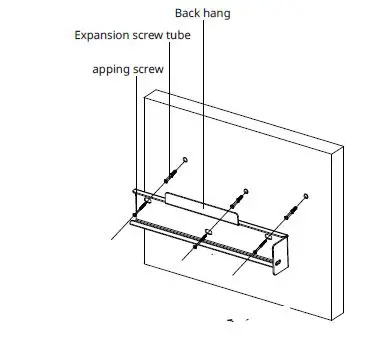
Place SCB2000 on the wall-mounted bracket as illustrated.
HorizontaAl Placement
The SCB2000 can be placed horizontally.The SCB2000 needs to be placed indoors at a location where it can be fixed.
Port and wiring instructions
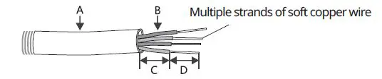
Voltage lnput Port(L1\L2\L3\PE.
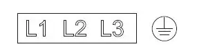
Input line voltage range:AC342-690V ; AC frequency:50/60HZ.
Multiple strands of soft copper wire
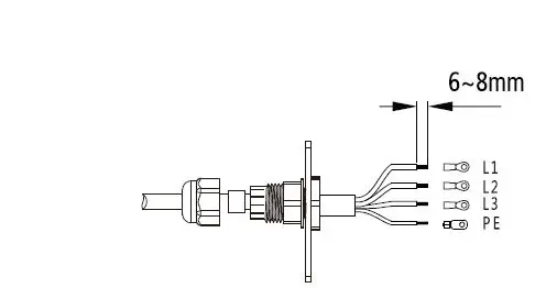
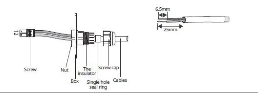
| No. | Description | Content |
| A | Wire Diameter | No more than 25 mm |
| B | Cross Sectional Area of Copper Wire | Recommend:2.5-4mm2 |
| C | Wire Length | About 130mm(PE line about 50mm) |
| D | Length of Bare Copper Wire | About 6~8mm(5~6mm for PE) |
LAN port
LAN version SCB2000 uses this port when using network cable.
RS485 port
Use this port when connecting ring tester and other third-party devices to RS485 line.
Fiber port
Fiber optic version SCB2000 USES this port when using fiber optic cable connection.
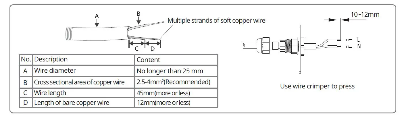
LN power port
Connect LN single-phase power supply, 110-240vac, 50/60hz to supply SCB2000.
Specification and crimping of Single phase power cord
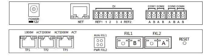
LAN Network port
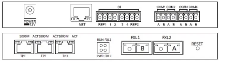
LAN SCB2000 uses this port when accessing a network cable;The access point is as shown in the NET position in the figure above.The description of bottom label inside SCB2000 is as follows
| No. | Port | Description |
| 1 | POWER | DC Power Input (Occupied) |
| 2 | NET | Ethernet lnterface |
| 3 | DI | DRED or RCR functional interface |
| 4 | NC | reserve |
| 5 | COM1 | This port is not used |
| 6 | COM2 | This port is not used |
| 7 | COM3 | This port is not used |
| 8 | COM4 | Connect with third party equipment such as environmental detector |
| 9 | TP1,TP2 | Ethernet Interface |
| 10 | TP3 | Ethernet Interface(Occupied) |
| 11 | FXL1,FXL2 | SC fiber optic interface |
Wire specification and installation: It is recommended to use shielded twisted pair cables with conductor area 1mm2 for 485 communication cables.
lt is recommended to use Super Five Type of network cables. After wiring, use the fire-proof mud to seal the port, to ensure its protective performance.
Application scene
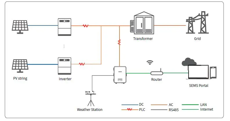
LAN or optical fiber can be used to communicate with the server, and an RS485 port can be reserved to connect with environmental monitor or other equipment. Multi machine fiber ring network.
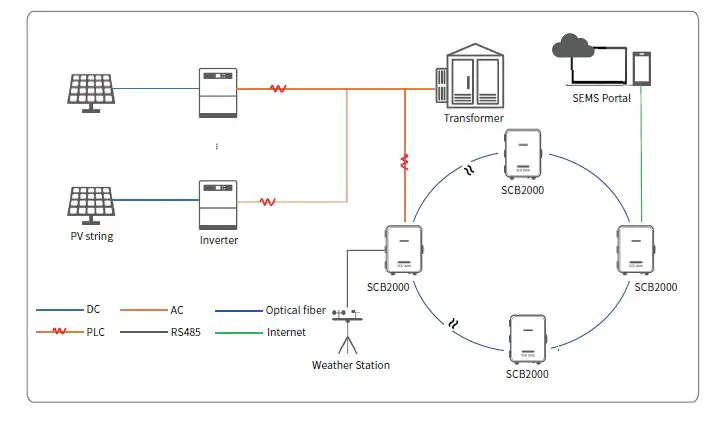
lf the choice of optical fiber version can be composed of fiber ring network. One SCB2000 should be set as the host (root node), and the other SCB2000 should be set as the slave (slave node). Please refer to 4.3 fiber switch configuration instructions for details
System is running
Ezlogger pro indicator light description

| port | State | Statements |
| POWER | The blue lights | Normal power supply |
| The blue lights went out | The power supply is abnormal | |
| RUN | Blue lights flashing(One second on, one second off ) | Ezlogger pro works properly |
| The blue light is always on or off | Ezlogger pro is not working properly | |
|
SERVER | Blue light normally on | Ezlogger pro connects to the server normally |
| Blue lights flashing (One second on,one second off ) | Ezlogger pro connects to the router but not to the server | |
| The blue lights went out | Ezlogger pro network notconnected | |
|
PC | The blue lights | Ezlogger pro connects to your computer and Promate software |
| The blue lights went out | Ezlogger pro is not connected to the computer and Promate software | |
|
COM1 | The blue lights | The number of inverters actually collected by Ezlogger pro is the same as that set by Promate |
| Blue lights flashing One second on, one second off | Ezlogger pro actually collects fewer inverters than Promate | |
| Blue lights flashing(One second on, three seconds off) | The Promate software does not set the number of inverters | |
| The blue lights went out | Ezlogger pro does not collect inverter data | |
| COM4 | The blue lights | The external equipment is normal |
| The blue lights went out | No external equipment |
System Settings
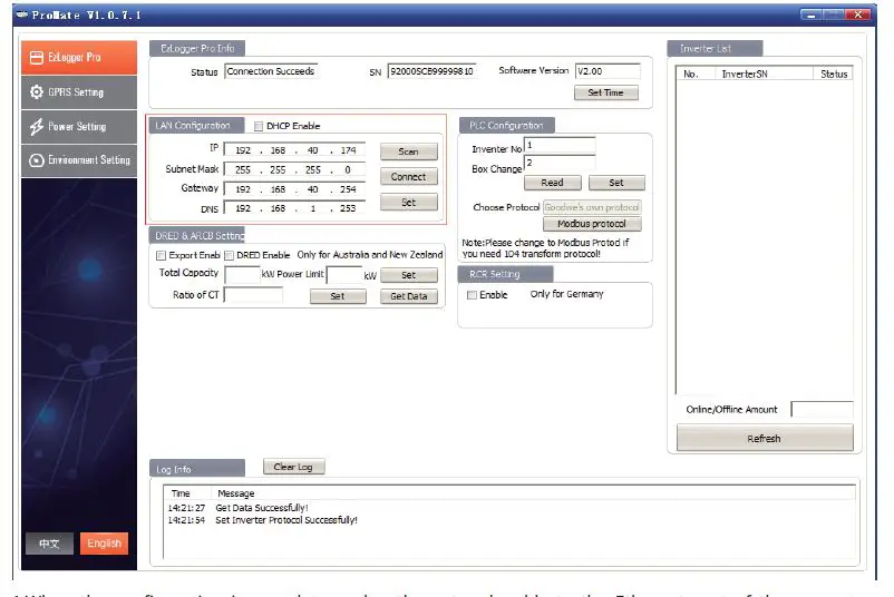
SCB2000 and inverter network, through the installation of Pormate monitoring software on the computer side of the SCB2000 monitoring and configuration.
ProMate is a kind of software that can configure EzLoggerPro, SCB2000 etc. It can modify the network lP address of EzLoggerPro and SCB2000, configure the number of connected inverters, time setting,RCR, DRED function, configuration and on-site debugging. First, the user need to install ProMate in the computer by downloading ProMate from lnternet ProMate1.0.7.1PLC.rar Please access to the website to download the program and compet the installation. lf the user needs to use ProMate software to configure SCB2000, it needs to be set in dynamic IP(DHCP) or static IP according to the network connection mode. lf the user is in the dynamic IP mode, he/she only needs to connect the SCB2000 NET port to the Router LAN port with the network cable to connect to the network, namely plug and play. lf the user has a static IP, it is necessary to switch SCB2000 to the static IP mode. That is, press the Reload key for about 10 seconds to reset and restart SCB2000,About 10 seconds after pressing the Reload button, the LED lights on the SCB2000 internal EzLogger Pro Panel will blink from rightto left and reset and restart.After restart, SCB2000 will be switched to static IP mode(default lP:192.168.1.200. Then use cables to connect SCB2000 NET port lf the optional fiber version is connected to the SCB2000 TP1 or TP2 port to the Ethernet port of the computer.at the same time, the lP address of the computer needs to be modified.
The IP address and the default gateway should be set at 192.168.1.xxx segment(1≤XXX≤250 and XXX ≠200).For example, the lP address can be set as 192.168.1.100 and the default gateway as 192.168.1.254.
When the configuration is complete,unplug the network cable to the Ethernet port of the computer and plug it into the router.At the same time can restore the computer’s IP address and other parameters to the default Settings.If the user wants to restore to dynamic IP mode, please press the RELOAD button for about 4 seconds.EzLogger Pro’s LED lights will flash from left to right and reset to restart.EzLogger Pro will be switched to dynamic lP mode after restart.
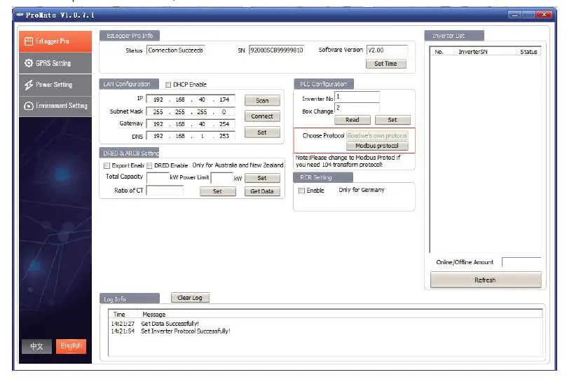
Protocol selection
Users can choose the protocol according to their needs. The gray one is the current protocol.After the protocol is switched,promate waits about one minute before proceeding.
Note
If the protocol is switched, the inverter device should be restarted.
 Optical fiber switch configuration instructions
 Optical fiber switch configuration instructions
lf the choice of fiber version please refer to this description
Some parameters of fiber optic switch: fiber optic switch is single-mode single-fiber,fiber interface SC, central wavelength 1310/1550nm;The transmission distance is 20KM
Use steps of optical fiber switch
Connect the fiber jumper or tail fiber from the end boxes at both ends of the fiber to the ports of the gigabit fiber switches (or the gigabit fiber interfaces of the transceiver or router at one end), Note that both ends of the same optical fiber must be connected to the TX and RX ports of the optical fiber interfaces at both ends, otherwise the optical fiber cannot be connected, and the single fiber module only needs one core optical fiber jumper.
Note
When optical fiber group ring network, there must be only one root node in one ring network, and the others are slave node devices.The gigabit network switch indicator lights are all defined as follows
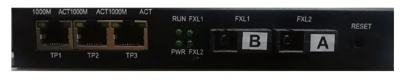
| PWR | Power indicator | The lights indicate the power supply is normal |
| RUN | System operation indicator | Slow Flash:The system is running well, flash, and the loop function is enabled |
| FXL1 | FXL1 Light mouth indicator light | Light: light port connection normal light Flash: light port has data communication |
| FXL2 | FXL2 Light mouth indicator light | Light: light port connection normal light Flash: light port has data communication |
| 1000M | Network light | Lights: expressed as a rate of 1000M |
| ACT | Network light | Flashlight: data transmission |
Reset and restore factory equipment
Long press RESET, RUN light Long bright, and then flash, quick. Grow after flashing, open RESET key, wait for RUN indicatorRestore to factory default when flashing slowly
Introduction to the use of the Ring Network
Login system default lP: 11.11.11.254 User name: root password: admin Conmect the opicalfiher to the computer through the network cable. Set the lP address of the computer to 11.11.11.xxx and enterthe URL 11.11.11.254 in the browser. Login screen appears.
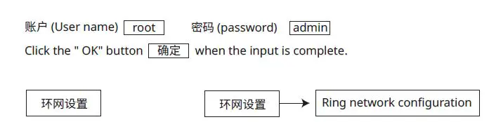
Pop up the following interface. Select second root nodes of ring network
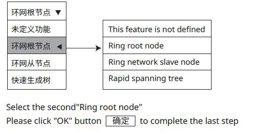 In the ring network configuration ring network, only one of them needs to be configured as a ring root node.Others do not need to be configured.Other defaults are that the ring network is from the node. IP Configuration To faclitate management, IP addresses can be modified, and each device must be within the same IP address segment. lf one or more devices in the ring network can not work properly, please insert one set of optical fibers after replacement, and then insert another set of optical fibers after the equipment system is activated.
Maintenance and troubleshooting
Note
During system maintenance, please power off the system.Please ensure that all power supply has been disconnected before the operation.
Maintenance
Maintenance contents
Please ensure that there is no strong EMl equipment around SCB2000. Please ensure that no heat source is placed around SCB2000. Check the SCB2000 wiring cable regularly for signs of looseness.Make sure the cables are firmly connected.
Fault handling
Typical fault
| The serial number | System failure | possible cause | proposal |
|
1 |
The system is not powered on | The socket is not powered. | Check that the LN power input is normal |
| The adapter ac input is not plugged in | Check the adapter to ensure that the ac input is fully plugged into the socket | ||
| The adapter dc output is not plugged in | Check the adapter to ensure that the dc output is plugged into POWER==12V | ||
| Power adapter failure | Replace the power adapter | ||
| SCB2000 system failure | Please contact the supplier or goodwe after sale | ||
|
2 |
The inverter device is not available on ProMate software | The three-phase ac power line is not connected | Check whether the three -phase ac power line is not connected and reconnect it |
| The number of devices is not set | Set according to the actual number of inverters connected | ||
| PLC communication board fault | Please contact the supplier or goodwe after sale |
Technical Data
| Model / Name | SCB2000(Solar Communication Box) | |
| Pvolwtaegreaidnapputter | PVolwtaegresuRpapnlgyeInput | AC110V~240V |
| frequency range | 50Hz/60Hz | |
| Voltage Range of lnput AC line | AC342V ~690v | |
| Rated Power Consumption | ≤18w | |
| communication | with the inverter | power line |
| with the server | LAN/GPRS/ optical fiber | |
| Max quality of lnverter connected | 30 | |
| Max Length to Server/Cloud | LAN :100m optical fiber : 20km | |
| RS485 | lt can be conennevcitreodntmoetnhtiradl -mpaorntiytodresvices such as | |
| other interface | USB,SD | |
| FPiabrearmeters | Centre wavelength | 1310/1550nm |
| transmission distance | 20KM | |
| optical port | A port:1550(Transmission)1310( Reception) | |
| B port:1310(Transmission) 1550( Reception) | ||
| MSpeecchiafinciactaiol ns | Size(Width*Height* Depthmm) | 460×350×143mm |
| Weight(KG) | with optical fiber 10.5kg; without optical fiber9.9kg | |
| Protection Degree | IP65 | |
| lnstallation | Wall mounting, bracket mounting, pole mounting | |
| Operating Temperature Range(°C) storage temperature(°C) | -20 ~+60°C – 30 ~+70°C | |
| 0-100% | ||
| Relative Humidity Altitude | ||
| <4000m | ||


