
LEVITON Inform App
INSTALLATION INSTRUCTIONS
ELECTRICAL SERVICE
For instructions on the installation and connection of the switch to the electrical service, refer to the installation instructions included in the box. Instruction sheets can also be found on www.leviton.com.
Cabling
RS-485 is a three-wire bus. One twisted pair is required for the two data signal wires, plus an additional wire for a common reference, which does not need to be twisted. A cable with two twisted pairs may also be used, where one or both conductors of the second pair is/are used for the common.
Shielding
A shield may not be needed for short networks, but is recommended and required for long networks or networks in an electrically noisy environment. The shield must be connected to a ground point at ONE side only. Although the shield can be used for the common reference, it is preferable to use a separate wire for the common.
Termination
RS-485 (EIA-485) networks typically require a termination resistor of 120Ω. Depending on the bus, a termination resistor may be needed. Additional bias resistors may also be needed.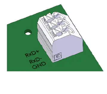
Topology
Utilize a daisy-chain bus configuration for connecting up to 32 devices.
Connection
The terminal block on the Modbus communication PCBA can accommodate 24 – 16 AWG cable. Connect the communication cable to the terminal block on the Modbus PCBA.
MODBUS CONFIGURATION
The following describes the Modbus commands and messages. The basic instructions should be adequate for Modbus host programming. The Modbus Interface requires about 150 ms to read sensor elements and respond. The default configuration is:
- Modbus address: 02
- Baud Rate: 19200
- Data Length: 8-bit
- Parity: Even
- Stop Bits: 1
NOTE:
To reset the communication parameters (including device address) to the factory default settings, press and hold the reset button (SW1) on the Display PCBA for 5 to 7 seconds)
SUPPORTED FUNCTIONS
| Function Code [dec] | Function Code [hex] | Action | Relevant Table |
| 03 | 03 | Read | Holding Registers |
| 04 | 04 | Read | Input Registers |
| 06 | 10 | Write | Holding Registers |
CONFIGURATION REGISTERS
The following registers represent the Modbus network communication parameters:
| Register Address | Data Address [Dec] | Data Address [Hex] | Data Type | Value Range | Default Value | |||
| Name | Min | Max | Description | |||||
| Address | 40001 | 0 | 0 | UINT16 | 1 | 247 | 2 | Value between 1 and 247 |
| Baud Rate | 40002 | 1 | 1 | UINT16 | 96 | 1152 | 192 | Modbus Baud rate value/ 100; 96: 9600, 192: 19200, 384: 38400, 576: 57600 |
| Parity | 40003 | 2 | 2 | UINT16 | 0 | 2 | 2 | 0: No parity, 2: Even Parity, 1: Odd Parity |
| Stop Bits | 40004 | 3 | 3 | UINT16 | 1 | 2 | 1 | |
| Data Length | 40005 | 4 | 4 | UINT16 | 8 | 8 | 8 | The Only acceptable value is 8 for RTU mode |
MEASUREMENT REGISTERS
The following registers represent the sensor and alarm outputs available:
| Name | Register Address | Modbus Data Address [Dec] | Modbus Data Address [Hex] | Number of Modbus Registers | Data Type | Description |
| Line 1 Voltage | 30001 | 0 | 0 | 1 | INT16 | Line 1 RMS Voltage (V) |
| Line 2 Voltage | 30002 | 1 | 1 | 1 | INT16 | Line 2 RMS Voltage (V) |
| Line 3 Voltage | 30003 | 2 | 2 | 1 | INT16 | Line 3 RMS Voltage (V) |
| Load 1 Voltage | 30004 | 3 | 3 | 1 | INT16 | Load 1 RMS Voltage (V) |
| Load 2 Voltage | 30005 | 4 | 4 | 1 | INT16 | Load 2 RMS Voltage (V) |
| Load 3 Voltage | 30006 | 5 | 5 | 1 | INT16 | Load 3 RMS Voltage (V) |
| Ground Status | 30007 | 6 | 6 | 1 | UINT16 | 1: GND/Earth Present, 0: GND/Earth Fault |
| Switch Status | 30008 | 7 | 7 | 1 | UINT16 | 1: Switch Open, 0: Switch Closed |
| Temperature | 30009 | 8 | 8 | 1 | INT16 | Temperature (°C); Multiply by 0.1 |
| Humidity | 30010 | 9 | 9 | 1 | UINT16 | Relative Humidity (%); 0-100 |
| Liquid Accumulation | 30011 | 10 | A | 1 | UINT16 | 1: Liquid Accumulation Detected, 0: Absence of Liquid |
| Line 1 Avg Voltage | 30012 | 11 | B | 1 | INT16 | Not yet implemented |
| Line 2 Avg Voltage | 30013 | 12 | C | 1 | INT16 | Not yet implemented |
| Line 3 Avg Voltage | 30014 | 13 | D | 1 | INT16 | Not yet implemented |
| Line 1 LED | 30015 | 14 | E | 1 | UINT16 | Line 1 Voltage State 0: Off (Normal), 2: Energized (Normal), 4: Improper Voltage |
| Line 2 LED | 30016 | 15 | F | 1 | UINT16 | Line 2 Voltage State 0: Off (Normal), 2: Energized (Normal), 4: Improper Voltage |
| Line 3 LED | 30017 | 16 | 10 | 1 | UINT16 | Line 3 Voltage State 0: Off (Normal), 2: Energized (Normal), 4: Improper Voltage |
| Load 1 LED | 30018 | 17 | 11 | 1 | UINT16 | Load 1 Voltage State 0: Off (Normal), 2: Energized (Normal), 4: Improper Voltage |
| Load 2 LED | 30019 | 18 | 12 | 1 | UINT16 | Load 2 Voltage State 0: Off (Normal), 2: Energized (Normal), 4: Improper Voltage |
| Load 3 LED | 30020 | 19 | 13 | 1 | UINT16 | Load 3 Voltage State 0: Off (Normal), 2: Energized (Normal), 4: Improper Voltage |
| GND LED | 30021 | 20 | 14 | 1 | UINT16 | Ground Continuity State 2: Normal, 4: Fault |
| Fault LED | 30022 | 21 | 15 | 1 | UINT16 | General warning error states 2: Normal, 6: Fault. Includes liquid accumulation sensor and internal communication state |
| Load 1 Current | 30023 | 22 | 16 | 2 | INT32 | Load 1 current in mA |
| Load 2 Current | 30025 | 24 | 18 | 2 | INT32 | Load 2 current in mA |
| Load 3 Current | 30027 | 26 | 1A | 2 | INT32 | Load 3 current in mA |
| Load 1 Avg Current | 30029 | 28 | 1C | 2 | INT32 | Not yet implemented |
| Load 2 Avg Current | 30031 | 30 | 1E | 2 | INT32 | Not yet implemented |
| Load 3 Avg Current | 30033 | 32 | 20 | 2 | INT32 | Not yet implemented |
DEVICE INFORMATION REGISTERS
The following registers represent the device information available:
| Name | Register Address | Modbus Data Address [Dec] | Modbus Data Address [Hex] | Number of Modbus Registers | Data Type | Description |
|
Wiring Config |
31001 |
1000 |
3E8 |
6 |
String* | 3-7 characters, plus null terminator: 1P+N+E = Single Phase, Neutral, Ground 2P+E = Single (split) Phase, Ground 2P+N+E = Single (split) Phase, Neutral, Ground 3P+E = Three-phase, Ground 3P+N+E = Three-phase, Neutral, Ground 3PB+E = 4-wire Delta B leg high
3PB+N+E = 5-wire Delta B leg high 3PB+E = 4-wire Delta B leg high 3PB+N+E = 5-wire Delta B leg high 3PC+E = 4-wire Delta C leg high 3PC+N+E = 5-wire Delta leg high C 3PC+E = 4-wire Delta C leg high 3PC+N+E = 5-wire Delta C leg high |
| Voltage Config | 31007 | 1006 | 3EE | 2 | uint16 | DIP switch-based user-configured nominal voltage |
| Reserved | 31013- 31100 | 87 | ||||
| Model Number | 31101 | 1100 | 44C | 32 | String* | Device model number; 1-63 characters, plus null terminator |
| Serial Number | 31133 | 1132 | 46C | 16 | String* | Device serial number; 1-31 characters, plus null terminator |
| Display PCBA FW Version | 31149 | 1148 | 47C | 6 | String* | Display PCBA firmware version; 5-11 characters plus null terminator |
| Power Sense PCBA FW Version | 31155 | 1154 | 482 | 6 | String* | Power Sense PCBA firmware version number; 5-11 characters |
| Modbus PCBA FW Version | 31161 | 1160 | 488 | 6 | String* | Modbus board firmware version number; 5-11 characters |
SENSOR DATA FORMAT
Sensor data as delivered as signed and unsigned integers and strings. Consequently, numeric conversion may be required to display in preferred conventional units.
Voltage Format
The voltage value displayed for Line 1, Line 2, Line 3, Load 1, Load 2, and Load 3 is the measured RMS phase voltage measured at their respective switch terminals. Line 1 Avg, Line 2 Avg, and Line 3 Avg are calculated values. Volts (V) = ModbusData.
Current Format
The current value displayed for Line 1 Current, Line 2 Current, and Line 3 Current is the measured RMS current in milliamps. Line 1 Avg Current, Line 2 Avg Current, and Line 2 Avg Current are calculated values. Amps (A) = (ModbusData) /1000
Temperature Format
The measured temperature range is -40.0°C to 125.0°C. The Modbus data range is -400 to 1250. Temperature (°C) = (ModbusData) /10.
Humidity Format
The measured relative humidity range is 0% to 100%. The Modbus data range is 0 to 100. Relative Humidity (%) = ModbusData.
Ground Continuity
The ground continuity sensor has a two-state output: present or fault. The Modbus data is 0 (fault) or 1 (present).
Liquid Accumulation
The liquid accumulation sensor has a two-state output: liquid absent or present. The Modbus data is 0 (absent) or 1 (present).
Switch Position
The switch position sensor has a two-state output: switch open or closed. The Modbus data is 0 (closed) or 1 (open).
ERROR DETECTION
The Inform technology firmware processes the sensor outputs to determine if they are normal for the specified operating conditions. There are a series of status registers that can be used for alerting abnormal operating conditions. These registers control the LED display on the device and are also available to external devices.
Voltage alarms
The voltage sensor outputs, switch position indicator output, and device configuration settings are analyzed to determine if the voltage level present on each switch terminal is normal. These registers are Line 1 LED, Line 2 LED, Line 3 LED, Load 1 LED, Load 2 LED, and Load 3 LED.
- Unused terminals yield a “normal – OFF” output.
- Load side terminals that are de-energized with the switch turned to the off position also yield an “OFF – normal” output.
- An RMS voltage of ≤ 50 V is classified as “de-energized”.
- Applicable line side terminals and corresponding load side terminals that are energized when the switch handle is turned to the ON position yield an “Energized – normal” output.
- Terminals with voltage present when there should not be, or improper voltage level, yield an output of “improper voltage level.”
- The Modbus data is 0 (Off – Normal), 2 (Energized – Normal), or 4 (Improper voltage level).
Ground Continuity Alarm
This alarm is a redundant register for indicating the ground continuity sensor’s status, either normal or fault. The Modbus data is 2 (Normal) or 4 (Fault).
General Fault Alarm
This register is a “catch-all” for a variety of error conditions. If the device experiences any internal communication failures between the sensor and processing electronics or the liquid accumulation sensor detects liquid, an alarm will be generated. The Modbus data is 2 (normal) or 6 (error detected).
| Situation | Error Response | Modbus Error Code |
| Query is not an allowable action for the server (slave) | Invalid Function Error | 0x01 |
| Writing to an undefined holding register | Invalid Address Error | 0x02 |
| Writing invalid data to a holding register | Invalid Data Error | 0x03 |
| Reading undefined holding register | Invalid Address Error | 0x02 |
| Reading undefined input register | Invalid Address Error | 0x02 |
| Incorrect CRC | None | N/A |
| Incorrect Parity | None | N/A |
| Incomplete Modbus Message | None | N/A |
| Incorrect interbyte timing | None | N/A |


