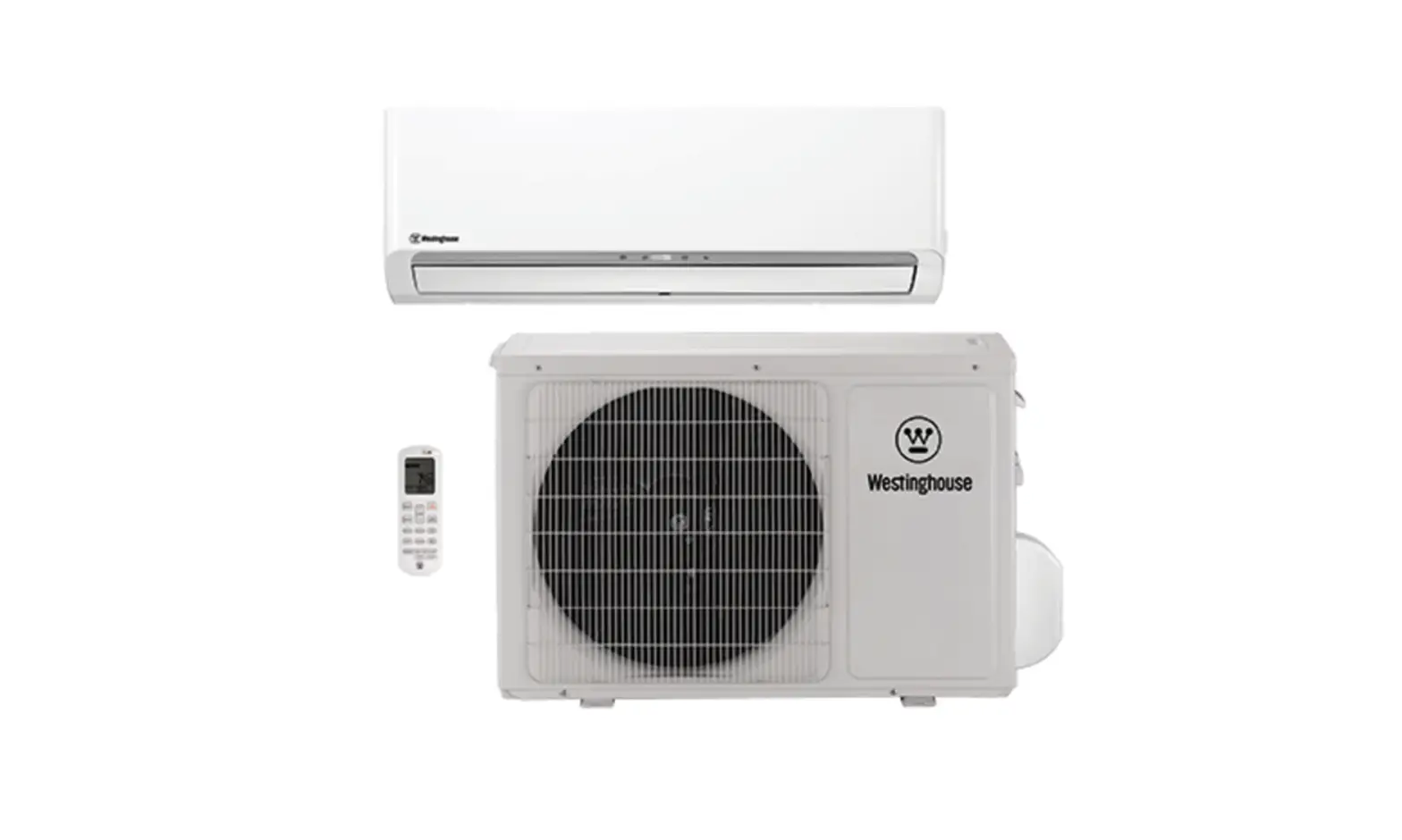
Westinghouse WHZ09WMA21S AIR CONDITIONER Wall mounted User Manual
INDOOR UNIT
Specifications
| Type | Wall mounted | |||||
| Inverter heat pump | ||||||
| Model name | WHZ09WMA21S | WHZ12WMA21S | ||||
| Power supply | 208/230 V ~ 60 Hz | |||||
| Power supply intake | Outdoor unit | |||||
| Available voltage range | 187—253 V | |||||
| Capacity | Cooling | Rated | kW | 2.64 | 3.52 | |
| Btu/h | 9,000 | 12,000 | ||||
| Min.—Max. | kW | 1.06—2.93 | 1.17—3.96 | |||
| Btu/h | 3,600—10,000 | 4,000—13,500 | ||||
| Heating | Rated | kW | 3.08 | 3.81 | ||
| Btu/h | 10,500 | 13,000 | ||||
| Min.—Max. | kW | 1.06—3.08 | 1.17—4.10 | |||
| Btu/h | 3,600—10,500 | 4,000—14,000 | ||||
| Input power | Cooling | Rated | kW | 0.560 | 0.780 | |
| Min.—Max. | 0.100—1.060 | 0.130—1.280 | ||||
| Heating | Rated | 0.770 | 0.855 | |||
| Min.—Max. | 0.130—1.220 | 0.170—1.430 | ||||
| Current | Cooling | Rated | A | 2.3 | 4.6 | |
| Heating | 3.4 | 4.8 | ||||
| EER | Cooling | W/W | 4.71 | 4.51 | ||
| Btu/hW | 16.07 | 15.40 | ||||
| COP | Heating | W/W | 4.00 | 4.45 | ||
| Btu/hW | 13.64 | 15.20 | ||||
| SEER | Cooling | Btu/hW | 28.0 | 25.0 | ||
| HSPF | Heating | Btu/hW | 12.5 | 12.0 | ||
| Power factor | Cooling | % | 97 | 96 | ||
| Heating | 97 | 97 | ||||
| Moisture removal | pints/h (L/h) | 1.9 (0.9) | 2.5 (1.2) | |||
| Maximum operating current*1 | Cooling | A | 6.5 | 7.0 | ||
| Heating | 6.5 | 7.0 | ||||
| Fan | Airflow rate | Cooling | HIGHER |
CFM (m3/h) | 394 (670) | 618 (1,050) |
| HIGH | 365 (620) | 559 (950) | ||||
| MED | 294 (500) | 483 (820) | ||||
| LOW | 235 (400) | 453 (770) | ||||
| LOWER | 224 (380) | 365 (620) | ||||
| Heating | HIGHER | 394 (670) | 618 (1,050) | |||
| HIGH | 365 (620) | 559 (950) | ||||
| MED | 294 (500) | 483 (820) | ||||
| LOW | 235 (400) | 453 (770) | ||||
| LOWER | 224 (380) | 365 (620) | ||||
| Type × Q’ty | Crossflow fan × 1 | |||||
| Motor output | W | 25 | 35 | |||
| Sound pressure level*2 | Cooling | HIGHER |
dB (A) | 42 | 48 | |
| HIGH | 39 | 46 | ||||
| MED | 34 | 41 | ||||
| LOW | 31 | 37 | ||||
| LOWER | 28 | 30 | ||||
| Heating | HIGHER | 42 | 48 | |||
| HIGH | 39 | 46 | ||||
| MED | 34 | 41 | ||||
| LOW | 31 | 37 | ||||
| LOWER | 28 | 30 | ||||
| Heat exchanger type | Dimensions (H × W × D) | in (mm) | 11-9/16 × 24-7/16 × 1-1/16 (294 × 620 × 27.2) | 14-7/8 × 27-3/4 × 1-1/16 (378 × 705 × 27.2) | ||
| Fin pitch | FPI | 18 | ||||
| Rows × Stages | 2 × 14 | 2 × 18 | ||||
| Pipe type | Copper | |||||
| Fin type | Aluminum | |||||
| Enclosure | Material | Polystyrene | ||||
| Color | White | |||||
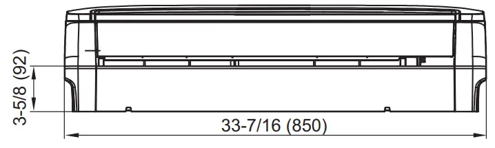
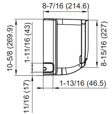
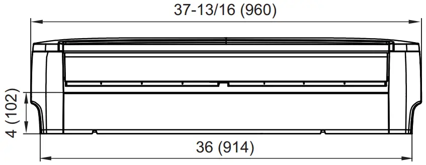
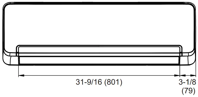
| Dimensions (H × W × D) | Net | in (mm) | 10-5/8 × 33-7/16 × 8-7/16 (270 × 850 × 215) | 12-3/8 × 37-13/16 × 9-5/16 (315 × 960 × 236) | ||
| Gross | 13-3/16 × 37 × 10-7/16 (335 × 940 × 265) | 15-3/8 × 40-15/16 × 12-7/16 (390 × 1,040 × 316) | ||||
| Weight | Net | lb (kg) | 20 (9) | 29 (13) | ||
| Gross | 24 (11) | 33 (15) | ||||
| Connection pipe | Size | Liquid | in (mm) | Ø1/4 (Ø6.35) | ||
| Gas | Ø3/8 (Ø9.52) | |||||
| Method | Flare | |||||
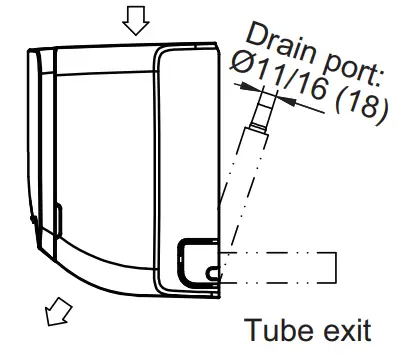
| Drain hose | Material | PE/PVC | ||||
| Tip diameter | in (mm) | Ø5/8 (Ø15.4) (I.D.), Ø7/8 (Ø23) (O.D.) | ||||
| Operation range | Cooling | °F (°C) | 61 to 86 (16 to 30) | |||
| %RH | 80 or less | |||||
| Heating | °F (°C) | 61 to 86 (16 to 30) | ||||
| Remote controller type | Wireless (Wired [option]) | |||||
NOTES:
| ||||||
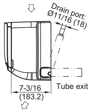
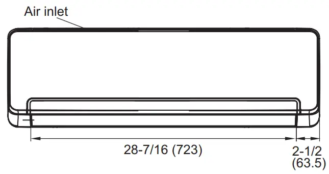
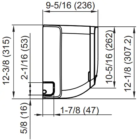
Dimensions
Model: WHZ09WMA21S
Model: WHZ12WMA21S
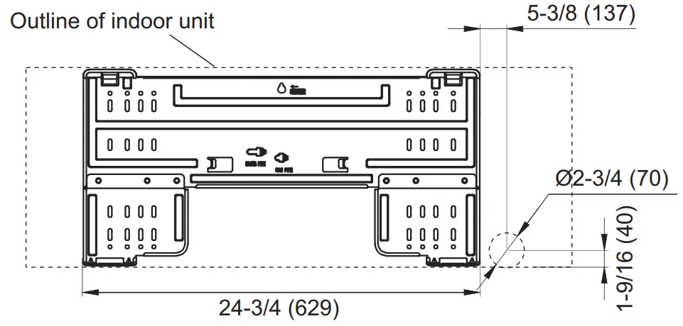
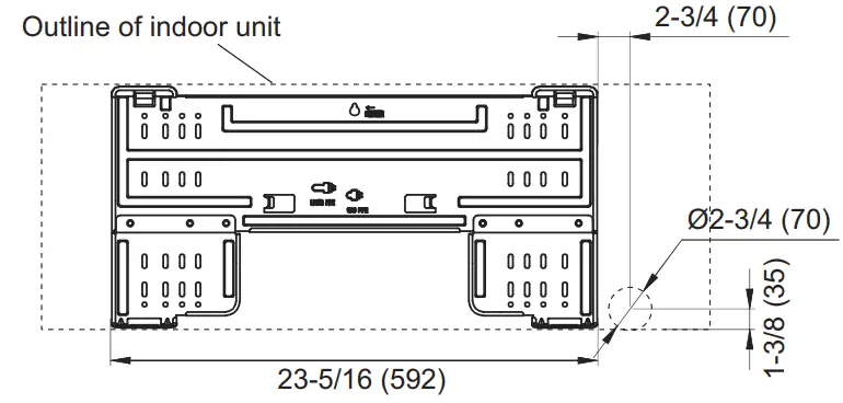
Installation space requirement
Provide sufficient installation space for product safety.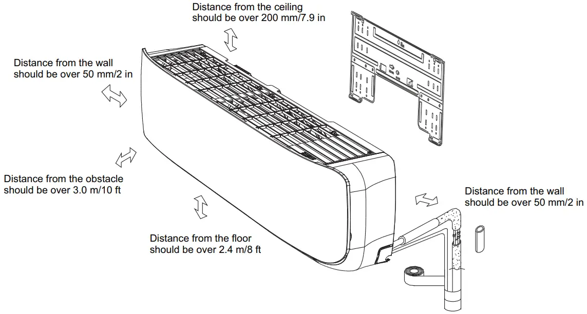
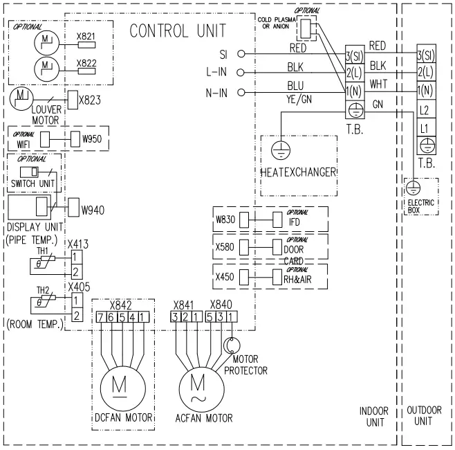
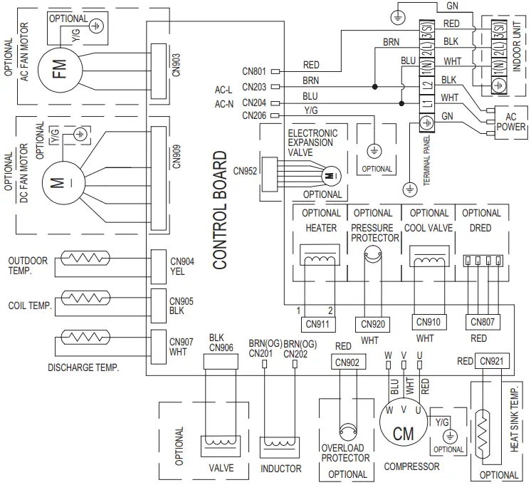
Wiring diagrams
Models: WHZ09WMA21S and WHZ12WMA21S
| Temperature | 0 °C 32 °F | 20°C 68 °F | 30°C 86 °F |
| Thermistor ( Pipe temp. ) | 15 k Ω 1.3 V | 6.5 k Ω 2.2 V | 4.5 k Ω 2.7 V |
| Thermistor ( Room temp. ) | 15 k Ω 1.3 V | 6.5 k Ω 2.2 V | 4.5 k Ω 2.7 V |
Fan motor
| Pin No. | Terminal code | Function of terminal | Lead wire color |
| 1 | Vm | Motor power voltage input | Red |
| 2 | — | — | — |
| 3 | — | — | — |
| 4 | GND | GND | Black |
| 5 | Vcc | Control power voltage input | White |
| 6 | FG | Revolution pulse output | Blue |
| 7 | Vsp | Speed control voltage input | Yellow |
Capacity table
Capacity tables show each of following values calculated based on the outdoor temperature and the indoor temperature, under given Airflow Rate (AFR):
For cooling capacity: Total Capacity (TC), Sensible Heat Capacity (SHC), and Input Power (IP)
For heating capacity: Total Capacity (TC) and Input Power (IP)
Cooling capacity
Model: WHZ09WMA21S
| AFR | CFM | 394 |
| Indoor temperature | ||||||||||||||||||||
| °FDB | 64 | 70 | 75 | 80 | 85 | 90 | ||||||||||||||
| °FWB | 54 | 60 | 83 | 67 | 71 | 73 | ||||||||||||||
| Outdoor temperature | °FDB | °FWB | TC | SHC | IP | TC | SHC | IP | TC | SHC | IP | TC | SHC | IP | TC | SHC | IP | TC | SHC | IP |
| kBtu | kW | kBtu | kW | kBtu | kW | kBtu | kW | kBtu | kW | kBtu | kW | |||||||||
| 14 | 12 | 6.64 | 5.25 | 0.38 | 8.01 | 5.31 | 0.38 | 8.26 | 5.43 | 0.38 | 9.07 | 6.51 | 0.37 | 9.34 | 5.86 | 0.35 | 10.26 | 7.52 | 0.37 | |
| 23 | 21 | 6.47 | 5.01 | 0.38 | 7.91 | 5.22 | 0.4 | 8.27 | 5.51 | 0.4 | 8.85 | 5.78 | 0.41 | 9.68 | 6.19 | 0.38 | 9.56 | 6.57 | 0.36 | |
| 32 | 28 | 7.51 | 5.24 | 0.32 | 8.18 | 5.48 | 0.35 | 8.52 | 5.83 | 0.36 | 8.86 | 6.21 | 0.36 | 9.17 | 6.53 | 0.37 | 9.32 | 6.91 | 0.36 | |
| 41 | 37 | 7.57 | 5.48 | 0.2 | 8.39 | 5.83 | 0.28 | 8.46 | 6.36 | 0.27 | 8.65 | 6.56 | 0.28 | 8.84 | 6.89 | 0.28 | 8.87 | 7.24 | 0.28 | |
| 50 | 47 | 8.62 | 5.73 | 0.37 | 8.77 | 6.21 | 0.32 | 8.82 | 6.65 | 0.32 | 8.94 | 6.88 | 0.32 | 9.08 | 7.21 | 0.32 | 9.19 | 7.58 | 0.31 | |
| 59 | 50 | 8.78 | 6.05 | 0.42 | 9.45 | 6.61 | 0.42 | 9.63 | 7.01 | 0.43 | 9.84 | 7.26 | 0.43 | 10.01 | 7.56 | 0.43 | 10.14 | 7.91 | 0.43 | |
| 67 | 53 | 8.85 | 6.42 | 0.49 | 9.17 | 6.98 | 0.6 | 9.85 | 7.3 | 0.61 | 10.78 | 7.55 | 0.61 | 11.72 | 7.89 | 0.6 | 11.12 | 8.23 | 0.6 | |
| 77 | 62 | 10.15 | 6.16 | 0.75 | 11.17 | 6.62 | 0.82 | 11.81 | 6.89 | 0.93 | 12.26 | 7.17 | 0.84 | 12.93 | 7.53 | 0.82 | 12.44 | 7.87 | 0.85 | |
| 87 | 69 | 9.18 | 5.85 | 0.74 | 10.25 | 6.23 | 0.92 | 10.95 | 6.54 | 0.95 | 11.28 | 6.83 | 0.95 | 11.59 | 7.21 | 0.96 | 11.18 | 7.54 | 0.95 | |
| 95 | 75 | 9.14 | 5.57 | 0.82 | 9.46 | 5.82 | 0.9 | 10.25 | 6.21 | 0.95 | 10.63 | 6.5 | 0.94 | 10.56 | 6.87 | 0.93 | 11.78 | 7.21 | 0.94 | |
| 104 | 78 | 7.51 | 5.23 | 0.82 | 8.48 | 5.47 | 0.9 | 9.33 | 5.89 | 0.94 | 9.85 | 6.27 | 0.94 | 10.24 | 6.52 | 0.92 | 10.96 | 6.87 | 0.92 | |
| 115 | 80 | 7.18 | 4.91 | 0.82 | 7.93 | 5.23 | 0.9 | 8.29 | 5.52 | 0.9 | 9.25 | 5.95 | 0.91 | 9.64 | 6.17 | 0.91 | 10.27 | 6.52 | 0.91 | |
Model: WHZ12WMA21S
| AFR | CFM | 618 |
| Indoor temperature | ||||||||||||||||||||
| °FDB | 64 | 70 | 75 | 80 | 85 | 90 | ||||||||||||||
| °FWB | 54 | 60 | 83 | 67 | 71 | 73 | ||||||||||||||
| Outdoor temperature | °FDB | °FWB | TC | SHC | IP | TC | SHC | IP | TC | SHC | IP | TC | SHC | IP | TC | SHC | IP | TC | SHC | IP |
| kBtu | kW | kBtu | kW | kBtu | kW | kBtu | kW | kBtu | kW | kBtu | kW | |||||||||
| 14 | 12 | 9.92 | 7.31 | 0.7 | 10.53 | 7.59 | 0.71 | 10.99 | 7.92 | 0.72 | 11.42 | 8.24 | 0.73 | 11.9 | 8.59 | 0.73 | 1253 | 8.69 | 0.74 | |
| 23 | 21 | 9.89 | 7.23 | 0.78 | 10.45 | 7.58 | 0.78 | 10.92 | 7.92 | 0.75 | 11.37 | 8.23 | 0.76 | 11.88 | 8.56 | 0.74 | 12.33 | 8.98 | 0.75 | |
| 32 | 28 | 10.12 | 7.58 | 0.79 | 10.77 | 7.93 | 0.79 | 11.35 | 8.23 | 0.8 | 11.82 | 8.54 | 0.81 | 12.33 | 8.89 | 0.82 | 12.83 | 9.29 | 0.82 | |
| 41 | 37 | 10.71 | 7.94 | 0.87 | 11.21 | 8.23 | 0.89 | 11.74 | 8.56 | 0.88 | 12.18 | 8.87 | 0.88 | 12.72 | 9.23 | 0.87 | 13.31 | 9.56 | 0.88 | |
| 50 | 47 | 11.16 | 8.26 | 0.93 | 11.71 | 8.55 | 0.94 | 12.29 | 8.87 | 0.95 | 12.56 | 9.21 | 0.96 | 13.12 | 9.56 | 0.96 | 13.86 | 9.92 | 0.97 | |
| 59 | 50 | 11.64 | 8.57 | 1.01 | 12.13 | 8.89 | 1.01 | 12.61 | 9.23 | 1.02 | 13.11 | 9.56 | 1.02 | 13.63 | 9.92 | 1.03 | 14.22 | 10.25 | 1.03 | |
| 67 | 53 | 12.11 | 8.92 | 1.02 | 12.66 | 9.21 | 1.02 | 13.18 | 9.58 | 1.04 | 13.69 | 9.92 | 1.05 | 14.21 | 10.25 | 1.05 | 14.76 | 10.58 | 1.05 | |
| 77 | 62 | 12.82 | 8.57 | 1.11 | 13.14 | 8.86 | 1.14 | 13.82 | 9.24 | 1.15 | 13.95 | 9.51 | 1.16 | 14.43 | 9.88 | 1.16 | 14.51 | 10.22 | 1.17 | |
| 87 | 69 | 11.02 | 8.21 | 1.12 | 11.25 | 8.54 | 1.12 | 12.95 | 8.91 | 1.13 | 13.28 | 9.12 | 1.14 | 13.59 | 9.53 | 1.15 | 14.18 | 9.84 | 1.16 | |
| 95 | 75 | 10.54 | 7.92 | 1.11 | 11.46 | 8.21 | 1.12 | 12.25 | 8.42 | 1.13 | 12.63 | 8.72 | 1.13 | 13.16 | 9.17 | 1.14 | 13.78 | 9.48 | 1.15 | |
| 104 | 78 | 9.51 | 7.56 | 1.1 | 10.48 | 7.82 | 1.11 | 11.33 | 8.11 | 1.11 | 11.85 | 8.37 | 1.12 | 12.24 | 8.83 | 1.12 | 12.96 | 9.13 | 1.13 | |
| 115 | 80 | 9.18 | 7.23 | 1.1 | 9.93 | 7.44 | 1.1 | 10.29 | 7.75 | 1.11 | 11.25 | 8.05 | 1.11 | 11.64 | 8.47 | 1.11 | 12.27 | 8.77 | 1.12 | |
Heating capacity
NOTE: Values mentioned in the table are calculated based on the maximum capacity.
Model: WHZ09WMA21S
| AFR | CFM | 394 |
| Indoor temperature | ||||||||||||
| °FDB | 60 | 65 | 70 | 75 | 78 | |||||||
| Outdoor temperature | °FDB | °FWB | TC | IP | TC | IP | TC | IP | TC | IP | TC | IP |
| kBtu | kW | kBtu | kW | kBtu | kW | kBtu | kW | kBtu | kW | |||
| -13 | -15 | 6.25 | 0.93 | 6.05 | 0.95 | 5.71 | 0.96 | 5.66 | 0.97 | 5.52 | 0.99 | |
| -5 | -7 | 8.91 | 0.98 | 8.65 | 0.99 | 8.02 | 1.01 | 7.76 | 1.05 | 7.32 | 1.12 | |
| 5 | 3 | 9.96 | 1.06 | 9.81 | 1.08 | 9.61 | 1.08 | 9.11 | 1.11 | 8.35 | 1.17 | |
| 14 | 12 | 10.12 | 1.08 | 10.01 | 1.11 | 9.86 | 1.11 | 9.61 | 1.12 | 9.47 | 1.13 | |
| 23 | 19 | 10.31 | 1.11 | 10.21 | 1.14 | 9.97 | 1.15 | 9.82 | 1.16 | 9.63 | 1.15 | |
| 32 | 28 | 10.65 | 1.18 | 10.42 | 1.15 | 10.23 | 1.15 | 10.03 | 1.15 | 9.84 | 1.16 | |
| 41 | 37 | 11.79 | 0.81 | 11.33 | 1.08 | 10.89 | 1.09 | 10.46 | 1.1 | 10.02 | 1.11 | |
| 47 | 43 | 12.61 | 1.04 | 12.48 | 1.06 | 11.78 | 1.09 | 11.28 | 1.09 | 10.68 | 1.11 | |
| 50 | 47 | 12.49 | 0.81 | 12.21 | 0.86 | 11.51 | 0.88 | 11.34 | 0.89 | 10.87 | 0.93 | |
| 59 | 50 | 12.55 | 0.82 | 12.34 | 0.87 | 11.85 | 0.88 | 11.63 | 0.89 | 10.95 | 0.92 | |
| 68 | 59 | 12.94 | 0.81 | 12.51 | 0.86 | 11.96 | 0.87 | 11.81 | 0.88 | 11.51 | 0.91 | |
| 75 | 65 | 13.33 | 0.81 | 12.72 | 0.85 | 12.52 | 0.86 | 12.12 | 0.87 | 11.73 | 0.86 | |
Model: WHZ12WMA21S
| AFR | CFM | 618 |
| Indoor temperature | ||||||||||||
| °FDB | 60 | 65 | 70 | 75 | 78 | |||||||
| Outdoor temperature | °FDB | °FWB | TC | IP | TC | IP | TC | IP | TC | IP | TC | IP |
| kBtu | kW | kBtu | kW | kBtu | kW | kBtu | kW | kBtu | kW | |||
| -13 | -15 | 9.16 | 1.25 | 8.95 | 1.24 | 8.79 | 1.24 | 8.56 | 1.25 | 8.32 | 1.25 | |
| -5 | -7 | 9.92 | 1.27 | 9.73 | 1.26 | 9.42 | 1.26 | 9.2 | 1.27 | 9.01 | 1.27 | |
| 5 | 3 | 10.58 | 1.33 | 10.36 | 1.32 | 10.11 | 1.32 | 9.87 | 1.33 | 9.61 | 1.33 | |
| 14 | 12 | 11.25 | 1.37 | 11.03 | 1.38 | 10.86 | 1.38 | 10.64 | 1.38 | 10.43 | 1.38 | |
| 23 | 19 | 12.12 | 1.41 | 11.97 | 1.42 | 11.57 | 1.43 | 11.34 | 1.42 | 11.22 | 1.43 | |
| 32 | 28 | 12.67 | 1.37 | 12.41 | 1.39 | 12.23 | 1.38 | 12.03 | 1.39 | 11.81 | 1.39 | |
| 41 | 37 | 14.02 | 1.39 | 13.89 | 1.38 | 13.69 | 1.39 | 13.46 | 1.39 | 13.23 | 1.38 | |
| 47 | 43 | 14.95 | 1.44 | 14.73 | 1.43 | 14.51 | 1.43 | 14.29 | 1.44 | 14.06 | 1.43 | |
| 50 | 47 | 14.65 | 1.42 | 14.43 | 1.41 | 14.12 | 1.42 | 13.93 | 1.38 | 13.71 | 1.42 | |
| 59 | 50 | 14.08 | 1.21 | 13.98 | 1.18 | 13.81 | 1.18 | 13.58 | 1.19 | 13.36 | 1.18 | |
| 68 | 59 | 12.97 | 1.15 | 12.72 | 1.13 | 12.56 | 1.12 | 12.35 | 1.13 | 12.13 | 1.12 | |
| 75 | 65 | 13.56 | 1.11 | 13.42 | 1.09 | 13.12 | 1.08 | 12.89 | 1.11 | 12.67 | 1.12 | |
Remote controller
Wireless remote controller
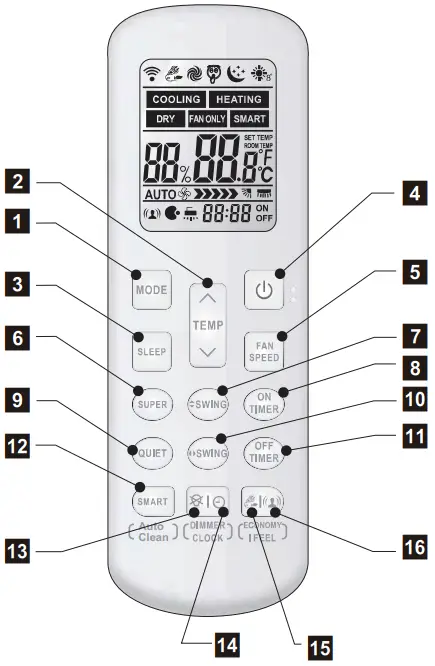
- 1. MODE
Press this button to select the operation mode. - 2. TEMP

Used to adjust the room temperature and the timer, also real time. - 3. SLEEP
Used to set or cancel Sleep Mode operation - 4. POWER
The appliance will be started when it is energized or will be stopped when it is in operation, if you press this button. - 5. FAN SPEED
Used to select fan speed in sequence auto, higher, high, medium, low and lower. - 6. SUPER
Used to start or stop the fast cooling/heating. (Fast cooling operates at high fan speed with 16cC(61°F) set temp automatically ; Fast heating operates at auto fan speed with 30t (86°F) set temp automatically) - 7.
 SWING
SWING
Used to stop or start vertical adjustment louver swinging and set the desired up/ down airflow direction. - 8. ON TIMER
Used to set or cancel the timer operation. - 9. QUIET
Used to set or cancel Quiet Mode operation. - 10.
 SWING
SWING
Used to stop or start Horizontal adjustment louver swinging and set the desired left/right airflow direction. - 11. OFF TIMER
Used to set or cancel the timer operation. - 12. SMART(invalid for multi system)
Used to enter logic operation directly when the units is on. Auto Clean (invalid for multi system) will be activated by pressing SMART button more than 5 seconds under Cooling or Dry mode and be canceled by pressing SMART, POWER or VODE button.(Icon ” “will appear on LCD and disappear after around 30 minutes) - 13. DIMMER
When you press this button, all the display of indoor unit will be closed. Press any button to resume display. - 14. CLOCK
Used to set the current time. - 15. ECONOMY
Used to set or cancel Economy Mode operation. - 2 + 3 8°C HEAT(optional)
Used to start or stop 8°C HEAT mode. - IFEEL
Press to set IFEEL Mode operation. In IFEEL mode, the Air Conditioner operates basis temperature sensor fitted in remote instead of machine, Advice to use IFEEL mode and the remote put where the indoor unit receive signal easily. Press this button above 5 seconds, start or stop IFEEL mode.
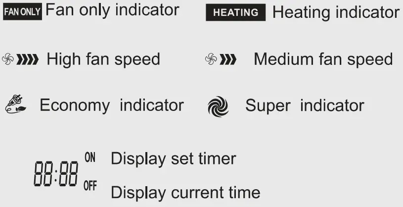
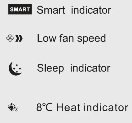
Indication symbols on LCD: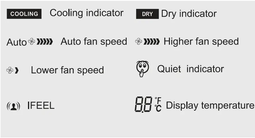
Wired remote controller
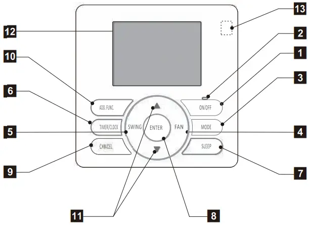
LCD screen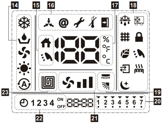
NOTE: Functions may differ by type of the indoor unit. For details, refer to the operation manual.
- ON/OFF button
Starts and stops operation. - Run indicator
Indicates the appliance is on. - MODE button
Switches operation mode (COOL, DRY, and HEAT). - FAN button
Selects the fan speed in sequence HIGH, AUTO, LOW,
MED, HIGH. - SWING button (invalid for some models)
Stops/Starts adjustment louver swing and sets the airflow direction. - TIMER/CLOCK button
Sets current time or set timer on/off. - SLEEP button
Sets/cancels sleep mode operation. - ENTER button
- CANCEL button
- ADD.FUNC. button (invalid for some models)
Sets filter clean, hot water, fresh air, electric heater, etc. - SET TEMP. (temperature) (
 / ) button
Sets desired temperature. - LCD screen
- Built-in infrared signal receiver
- Operation mode
 : Cooling mode,
  : Dry mode,
  : Fan only mode,
 : Heating mode,
  : Auto mode
 - Temperature mode
 : Room temperature,
  : Hot water temperature
 - Setting indicator
 : Central control,
  : Address setting,
  : Address setting, : Error indicator,
 : Temperature range limit,
  : Home leave control
 - Temperature indicator
 : Relative moisture,
  : Fahrenheit,
  : Celsius
 - Status indicator
 : Defrost,
 : Compressor run,
  : Filter clean,
  : Lock,
  : Air purge, : Hot water,
  : Ventilation,
  : Electric heater,
  : Sleep
 - Air direction indicator
- Day of week indicator
- Fan speed indicator
- Timer indicator
- Floor heater indicator
 : Fan only mode,
 : Heating mode,
  : Auto mode
 : Defrost,
Accessories
| Part name | Q’ty | Part name | Q’ty |
| Remote controller instructions | 1 | Drain joint rubber seal | 1 |
| Use and installation instructions | 1 | Flare nuts | 4 |
| Remote controller | 1 | Bag of wall anchors and screws | 1 |
| Remote controller holder | 1 | Screw for installations | 6 |
| AAA battery | 2 | Screw cover | 3 |
| Foam insulation | 09 model: 1 12 model: 2 | Warranty card | 1 |
| Drain joint | 1 | Rubber plug | 6 |
OUTDOOR UNIT
Specifications
| Type | Inverter heat pump | ||||
| Model name | WHZ09SZA21S | WHZ12SZA21S | |||
| Power supply | 208/230 V ~ 60 Hz | ||||
| Available voltage range | 187—253 V | ||||
| Fan | Airflow rate | CFM (m3/h) | 1,177 (2,000) | ||
| Type × Q’ty | Propeller fan × 1 | ||||
| Motor output | W | 30 | |||
| Sound pressure level *1 | dB (A) | 55 | |||
|
Heat exchanger type | Dimensions (H × W × D) | in (mm) | 33-1/16 × 21-1/2 × 11/16 (840 × 546 × 18.19) 33-1/16 × 21-1/2 × 11/16 (840 × 546 × 18.19) | 33-1/16 × 21-1/2 × 11/16 (840 × 546 × 18.19) 33-1/16 × 21-1/2 × 11/16 (840 × 546 × 18.19) 19-11/16 × 16-9/16 × 11/16 (500 × 420 × 18.19) | |
| Fin pitch | FPI | 18 | |||
| Rows × Stages | 2 × 26 | 2.5 × 26 | |||
| Pipe type | Copper | ||||
| Fin type | Type (Material) | Aluminum | |||
| Surface treatment | Blue fin | ||||
| Compressor | Type | Rotary | |||
| Refrigerant | Type | R410A | |||
| Charge | lb oz | 2 lb 7 oz | 2 lb 14 oz | ||
| g | 1,100 | 1,300 | |||
| Refrigerant oil | Type | VG74 (POE) | |||
| Enclosure | Material | Steel sheet | |||
| Color | White | ||||
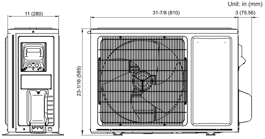
| Dimensions (H × W × D) | Net | in (mm) | 23-1/16 × 31-7/8 × 11 (585 × 810 × 280) | ||
| Gross | 25-3/16 × 37 × 15-3/16 (640 × 940 × 385) | ||||
| Weight | Net | lb (kg) | 75 (34) | 84 (38) | |
| Gross | 82 (37) | 93 (42) | |||
|
Connection pipe | Size | Liquid | in (mm) | Ø1/4 (Ø6.35) | |
| Gas | Ø3/8 (Ø9.52) | ||||
| Method | Flare | ||||
| Pre-charge length | ft (m) | 24.6 (7.5) | |||
| Max. length | 65 (20) | ||||
| Max. height difference | Indoor unit higher than outdoor unit: 32 (10) Outdoor unit higher than indoor unit: 16 (5) | ||||
| Operation range | Cooling | °F (°C) | -0.4 to 115 (-18 to 46) | ||
| Heating | -13 to 75 (-25 to 24) | ||||
NOTES:
| |||||
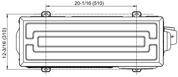
Dimensions
Models: WHZ09SZA21S and WHZ12SZA21S
Installation space
Models: WHZ09SZA21S and WHZ12SZA21S
Space requirement
Provide sufficient installation space for product safety.
![]() CAUTION
CAUTION
Keep the space shown in the installation examples.
If the installation is not performed accordingly, it could cause a short circuit and result in a lack of operating performance.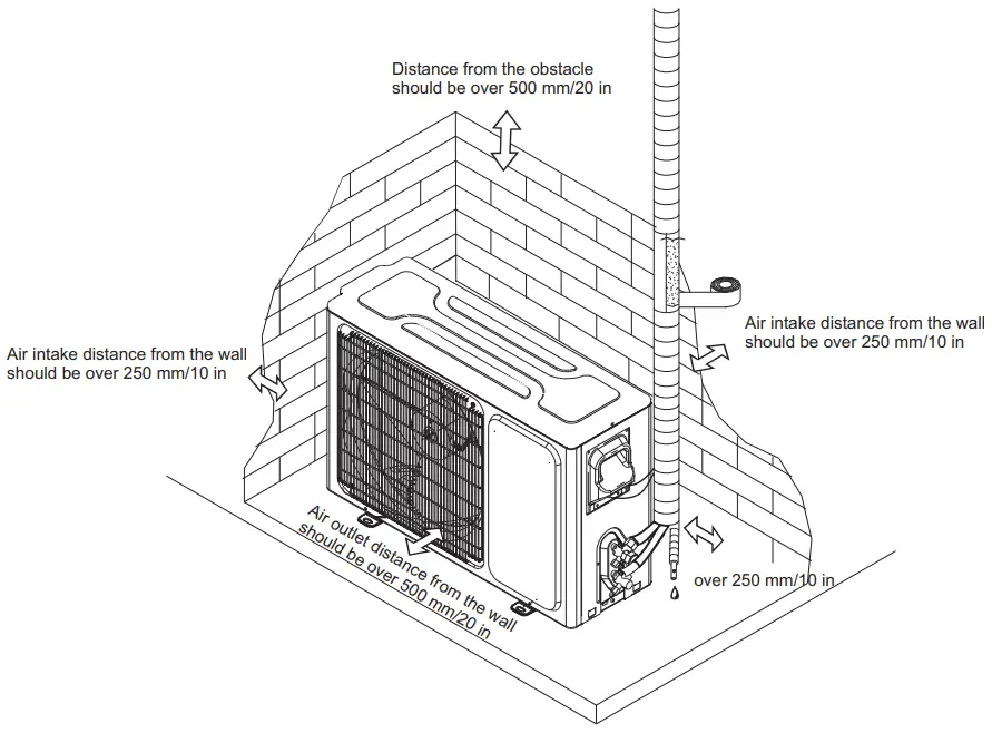
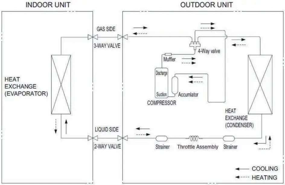
Refrigerant circuit
Models: WHZ09SZA21S and WHZ12SZA21S
Wiring diagrams
Models: WHZ09SZA21S and WHZ12SZA21S
Fan motor
| Pin No. | Terminal code | Function of terminal | Lead wire color |
| 1 | FG | Revolution pulse output | Blue |
| 2 | Vsp | Speed control voltage input | Yellow |
| 3 | Vcc | Control power voltage input | White |
| 4 | GND | GND | Black |
| 5 | — | — | — |
| 6 | Vm | Motor power voltage input | Red |
Compressor
09 model: 2.08 Ω
12 model: 1.82 Ω
(20°C 68 °F)
| Temperature | 0 °C | 32 °F | 20°C | 68 °F | 30°C | 86 °F |
| Thermistor ( ODU temp. ) | 15 k Ω 1.3 V | 6.5 k Ω 2.2 V | 4.5 k Ω 2.7 V | |||
| Thermistor ( Pipe temp. ) | 15 k Ω 1.3 V | 6.5 k Ω 2.2 V | 4.5 k Ω 2.7 V | |||
| Thermistor ( Discharge temp. ) | 187 k Ω 0.18 V | 72.1 k Ω 0.43 V | 46.5 k Ω 0.64 V | |||
Electrical characteristics
| Model name | WHZ09SZA21S | WHZ12SZA21S | |||
| Power supply | Voltage | V | 208/230 ~ | ||
| Frequency | Hz | 60 | |||
| MCA*1 | A | 6.5 | 7.0 | ||
| Wiring spec.*2 | MAX. CKT. BKR*3 | A | 15 | ||
| Power cable | AWG | 3 × 16 | |||
| Connection cable*4 | Size | AWG | 4 × 18 | ||
| Limited wiring length | ft (m) | 6.9 (21) | |||
- Minimum Circuit Ampacity (Calculation based on UL60335-2-40)
- Selected sample based on Japan Electro technical Standards and Codes Committee E0005. As the regulations of wire size and circuit breaker differ in each country or region, select appropriate devices complied to the regional standard.
- Maximum Circuit Breaker
- Limit voltage drop to less than 2%. If voltage drop is 2% or more, increase cable conductor size.
Accessories
| Part name | Q’ty | Part name | Q’ty |
| Use and installation instructions | 1 | Power wire | 1 |
| Bottom rubber for outdoor unit | 4 |


