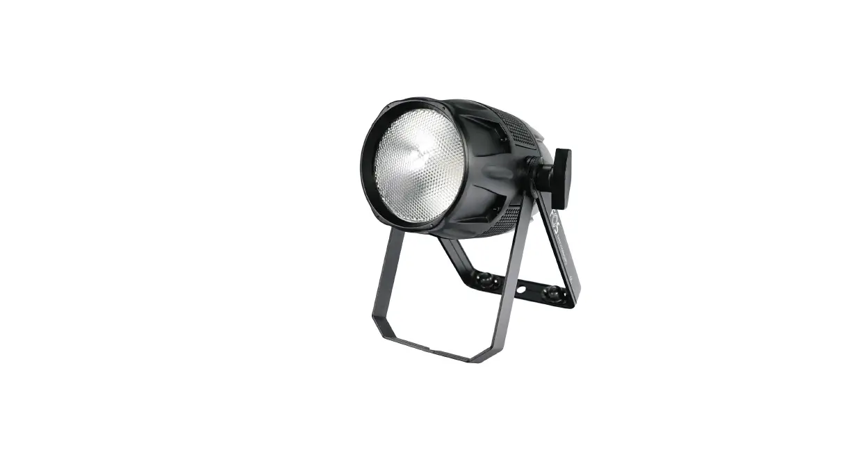
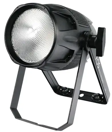
FOS technology Tour Par 150 Weatherproof Par
Thanks for choosing our goods please read this manual carefully before your operating and keep this manual for future needs
Thank you for purchasing LED Tour Par 150, Every unit has been thoroughly tested and has been shipped in perfect operating condition. Carefully check the shipping carton for damage that may have occurred during shipping. If the carton appears to be damaged, carefully inspect your fixture for any damage and be sure all accessories necessary to operate the unit has arrived intact. In the case damage has been found or parts are missing, please contact the manufacturer or your dealer for further instructions. You now own a professional lighting unit that offers endless possibilities.
For your own safety and that of others, please read this instruction manual carefully before installing the unit.
Anyone involved in installing, operating or servicing the LED Tour Par 150 must:
- Be a qualified, authorized professional
- Strictly follow the instructions in this user manual.
Please take the time to read this manual carefully and thoroughly before installing and operating the luminaire. You should have a good knowledge of its operating conditions and all pertinent product information.
After you have become familiar with this manual, we recommend that you keep a copy for future use. All the information found in this manual is subject to change without notice. We reserves the right to modify and upgrade its range of products, with no obligation to integrate these changes into products already sold.
Warning
- To prevent or reduce the risk of electrical shock or fire ,do not expose the unit to rain or moisture.
- Do not open the unit within five minutes after switching off.
- Please consider that damages caused by manual modifications to the device are not subject to warranty.
Installation
The unit should be mounted via its screw holes on the bracket.Always ensure that the unit is firmly fixed to avoid vibration and slipping while operating.And make sure that the structure to which you are attaching the unit is secure and is able to support a weight of 10 times of the unit’s weight. Also always use a safety cable that can hold 12 times of the weight of the unit when installing the fixture.
The equipment must be fixed by professionals.And it must be fixed at a place where is out of the touch of people and has no one pass by or under it.
Specifications and Features
- LEDs: 150W RGBW 4in1 LEDs
- Power Consumption:150W
- DMX Channels: 11 DMX Channels
- PMW Rate: 900Hz~10000Hz
- Dimmer Curve: 4 dimmer curve mode
- 6 DMX Channels Mode: 1CH,2CH,4CH,6CH,8CH,11CH
- Control Protocol: DMX
- Support RDM
- Color: White and black
- Each LED can pixel control.
- Fan Mode: Max, Smart/Slient
- Color temperature: 3000K~7600K
- Compact and lightweight housing
- XLR Connectors: Seetronic 3pin&5pin XLR Connector
- Powercon True1 in/out
- Work mode: Auto, DMX, Master/Slaver
- With handle and safe
- Power input:110~240V,50/60Hz
- Power Consumption:150W
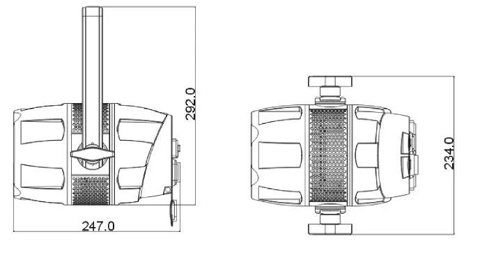
- Size: 307x234x247mm
- Net Weight: 3.5KG
Product View
Product Description

- Menu
- Pressure valve
- DMX IN/ DMX OUT
- POWER IN/POWER OUT
Control Panel
The control panel is the mechanism for configuring the LTP150 settings. It has a small LCD screen and four buttons, which are described below.
| Button | Function |
| <MENU> | Scrolls through the first level of options, or exits from the current menu or |
| function | |
| <UP> | Navigates upward through the menu list or increases the numeric value |
| when in a function | |
| <DOWN> | Navigates downward through the menu list or decreases the numeric value |
| when in a function | |
| <ENTER> | Enables the currently displayed menu or sets the currently selected value in |
| to the current function |
| DMX Address | 001-512 | |||
|
DMX Mode | 1CH | |||
| 2CH | ||||
| 4CH | ||||
| 6CH | ||||
| 8CH | ||||
| 11CH | ||||
|
Stand Alone |
Auto | Program 1 | Dim | 000-255 |
| Program 2 | Speed | 000-255 | ||
| Program 3 | ||||
| ….. | ||||
| Program 17 | MIXED | |||
| ColorMacro | Color Off | 000-005 | ||
| Color1~46 | 006-255 | |||
|
Manual | Dimmer | 000-255 | ||
| Strobe | 0~30Hz | |||
| Red | 000-255 | |||
| Green | 000-255 | |||
| Blue | 000-255 | |||
| White | 000-255 |
| CCT | OFF | |||
| 3000K/3500K/4500K/5500K/7500K | ||||
|
Settings | Display Reverse | On | Display Reverse | |
| Off | Normal | |||
| Display Backlight | On | Normal | ||
|
Off | Display off after 1 minute | |||
| DMX Fail | Hold | Keep the last status | ||
| Blackout | ||||
| ManualMode | ||||
|
Dimmer Curve | Standard | |||
| Stage | ||||
| TV | ||||
| Architectural | ||||
| Theatre | ||||
| Stage2 | ||||
| Dimmer Speed | 0.1-0.9s ~ 1-10S | Only for stage2 curve | ||
| AutoLock | On | |||
| Off | ||||
| Fan Mode | Smart | |||
| Max | ||||
| Silent | ||||
|
PWM Rate | 900Hz | |||
| 1000Hz | ||||
| 1100Hz | ||||
| 1200Hz | ||||
| 1300Hz | ||||
| 1400Hz | ||||
| 1500Hz | ||||
| 2500Hz | ||||
| 4000Hz | ||||
| 5000Hz | ||||
| 6000Hz | ||||
| 10000Hz | ||||
| Service | Reset | Passcode | Code: down, down, down, up, down, down,down, up | |
| Calibration | Passcode | Code: down, up, down, up, down, | ||
| down, down, down. | ||||
|
System Info | Firmwre | V1.0 | ||
| Operation Hours | xxxHrs | |||
| Temperatur e | xxx°C | |||
| RDM | Id number |
| 1 CH | VALUES | FUNCTIONS |
| 1 | 000-255 | Blinder Mode Channel 0%-100%, RedShift. Override other dimmer channel. |
| 2 CH | VALUES | FUNCTIONS |
| 1 | 000-255 | MASTER DIMMER 0%-100% |
|
2 | COLOR MACROS | |
| 000-007 | No Effect | |
| 008~255 | Color 1 ~46 |
| 4 CH | VALUES | FUNCTIONS |
| 1 | 000-255 | RED 0%-100% |
| 2 | 000-255 | GREEN 0%-100% |
| 3 | 000-255 | BLUE 0%-100% |
| 4 | 000-255 | WHITE 0%-100% |
6 DMX Channels:
| 6 CH | VALUES | FUNCTIONS |
| 1 | 000-255 | MASTER DIMMER 0%-100% |
| 2 | 000-255 | RED 0%-100% |
| 3 | 000-255 | GREEN 0%-100% |
| 4 | 000-255 | BLUE 0%-100% |
| 5 | 000-255 | WHITE 0%-100% |
|
6 | COLOR MACROS | |
| 000-007 | No Effect | |
| 008~255 | Color 1 ~46 | |
| SHUTTER & STROBING | ||
| 000-031 | LED Off | |
| 032-063 | LED On | |
| 064-095 | Strobing Slow – Fast | |
| 096-127 | LED On | |
| 128-159 | Pulse Strobing | |
| 160-191 | LED On | |
| 192-223 | Random Strobing Slow – Fast | |
| 224-255 | LED On |
| 8 CH | VALUES | FUNCTIONS |
| 1 | 000-255 | MASTER DIMMER 0%-100% |
| 2 | 000-255 | DIMMER FINE 0%-100% |
| 3 | 000-255 | RED 0%-100% |
| 4 | 000-255 | GREEN 0%-100% |
| 5 | 000-255 | BLUE 0%-100% |
| 6 | 000-255 | WHITE 0%-100% |
|
7 | SHUTTER & STROBING | |
| 000-010 | LED on | |
| 011-020 | LED Off | |
| 021-030 | Singe flash |
| 031-090 | Strobing slow – fast | |
| 091-100 | LED ON | |
| 101-170 | Pulse strobing | |
| 171-180 | LED on | |
| 181-240 | Random strobing slow -fast | |
| 241-255 | LED On | |
| 8 | 000-255 | Blinder Mode Channel 0%-100%, RedShift. Override other dimmer channel. |
| 11 CH | VALUES | FUNCTIONS |
| 1 | 000-255 | MASTER DIMMER 0%-100% |
| 2 | 000-255 | DIMMER FINE 0%-100% |
| 3 | 000-255 | RED 0%-100% |
| 4 | 000-255 | GREEN 0%-100% |
| 5 | 000-255 | BLUE 0%-100% |
| 6 | 000-255 | WHITE 0%-100% |
|
7 | SHUTTER & STROBING | |
| 000-010 | LED on | |
| 011-020 | LED Off | |
| 021-030 | Singe flash | |
| 031-090 | Strobing slow – fast | |
| 091-100 | LED ON | |
| 101-170 | Pulse strobing | |
| 171-180 | LED on | |
| 181-240 | Random strobing slow – fast | |
| 241-255 | LED On | |
| 8 | 000-255 | Blinder Mode Channel 0%-100%, RedShift. Override other dimmer channel. |
| 9 | COLOR MACROS |
| 000-007 | No Effect | ||||
| 008~255 | Color 1 ~46 | ||||
|
10 | DIMMER MODES | ||||
| 000-010 | Default to Unit Setting | ||||
| 011-020 | Standard | ||||
| 021-040 | Stage | ||||
| 041-060 | TV | ||||
| 061-080 | Architectural | ||||
| 081-100 | Theatre | ||||
| 101-120 | Stage 2 | ||||
| DIMMER DELAY TIME | |||||
| 121 | 0.1Sec. | ||||
| 122 | 0.2Sec. | ||||
| 123 | 0.3Sec. | ||||
| 124 | 0.4Sec. | ||||
| 125 | 0.5Sec. | ||||
| 126 | 0.6Sec. | ||||
| 127 | 0.7Sec. | ||||
| 128 | 0.8Sec. | ||||
| 129 | 0.9Sec. | ||||
| 130 | 1.0Sec. | ||||
| 131 | 1.5Sec. | ||||
| 132 | 2.0Sec. | ||||
| 133 | 3.0Sec. | ||||
| 134 | 4.0Sec. | ||||
| 135 | 5.0Sec. | ||||
| 136 | 6.0Sec. | ||||
| 137 | 7.0Sec. | ||||
| 138 | 8.0Sec. | ||||
| 139 | 9.0Sec. | ||||
| 140 | 10Sec. | ||||
| 141-255 | Default to Unit Setting | ||||
|
11 | REFRESH RATE | ||||
| 000-010 | Default to Unit Setting | ||||
| 011-020 | 900HZ | ||||
| 021-030 | 1000HZ | ||||
| 031-040 | 1100HZ | ||||
| 041-050 | 1200HZ | ||||
| 051-060 | 1300HZ | |
| 061-070 | 1400HZ | |
| 071-080 | 1500HZ | |
| 081-090 | 2500HZ | |
| 091-100 | 4000HZ | |
| 101-110 | 5000HZ | |
| 111-120 | 6000HZ | |
| 121-130 | 10000HZ | |
| 131-140 | Set refresh rate to unit default | |
| 141-150 | Fan mode silent | |
| 151-160 | Fan mode smart | |
| 161-170 | Fan mode max | |
| 171-180 | Set fan mode to unit default | |
| 181-255 | No function |
Troubleshooting
Following are a few common problems that may occur during operation.
Here are some suggestions for easy troubleshooting:
- The unit does not work, no light and the fan does not work
a. check the connection of power and main fuse.
b. Measure the mains voltage on the main connector.
c. Check the power on Led. - Not responding to DMX controller
a. DMX LED should be on. If not ,check DMX connectors, cables to see if link properly.
b. If the DMX LED is on and no response to the channel, check the address settings and DMX polarity.
c. If you have intermittent DMX signal problems, check the pins on connectors or on PCB of the unit or the previous one.
d. Try to use another DMX controller.
e. Check if the DMX cables run near or run alongside to high voltage cables that may cause damage or interference to DMX interface circuit. - Some units don’t respond to the easy controller
a. You may have a break in the DMX cabling. Check the LED for the response of the master/slave mode signal.
b. Wrong DMX address in the unit .Set the proper address. - One of the channels is not working well
a. The stepper motor might be damaged, or the cable connected to the PCB is broken.
b. The motor’s drive IC on the PCB might be out of condition. - Fixture Cleaning
The cleaning of internal and external optical lenses and/or mirrors must be carried out periodically to optimize light output. Cleaning frequency depends on the environment in which the fixture operates: dirt, smoky or particularly dirty surrounding can cause greater accumulation of dirt on the unit’s optics.
a. Clean with soft cloth using normal glass cleaning fluid.
b. Always dry the parts carefully.
Warranty
The LED Tour Par 150 fixture is guaranteed against manufacturing defects for the duration of two (2) years from the date of purchase.
This warranty does not cover the unit for evidence of physical shock or damage caused by abuse or any use not in accordance with the operating conditions set forth in the present user manual.
In addition, cosmetic defects caused by the normal wear and tear of the unit are not covered under the warranty.
Any modification to the fixture will void the warranty. We cannot under any circumstances be held liable for quality and conformity regarding the installation of this product, which is the responsibility of the installer. the device and before use, may be covered by the warranty.
The manufacturer is not responsible for any errors or omissions that may occur in this document. All information contained in this manual is subject to change without notice.


