KLUS WS WSD Series Dim to Warm Wall Switch Control
SYSTEM CONTENT AND ITEM IDENTIFICATION
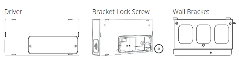
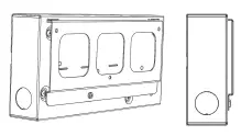
LED Driver
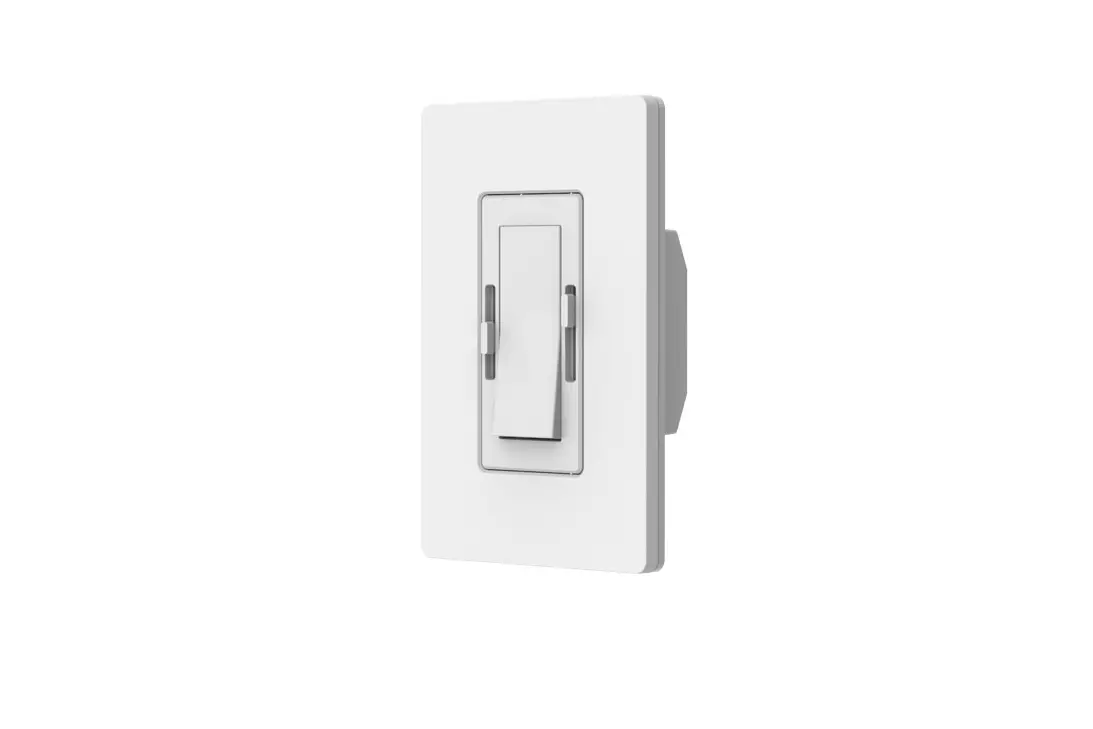
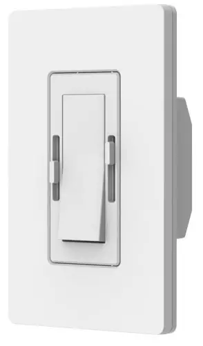
Wall Switch
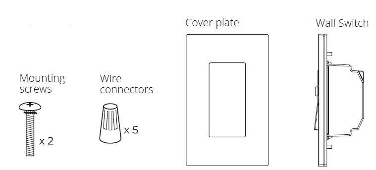
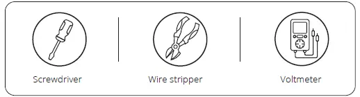
TOOLS NEEDED
IMPORTANT NOTES PLEASE READ BEFORE INSTALLATION
- All system parts work in compatibility ONLY with each other.
- DO NOT attempt to install with parts from other manufacturers.
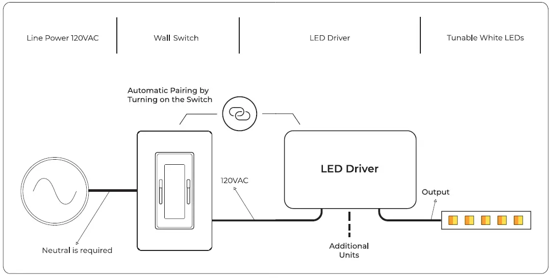
- The system requires a Neutral wire. If you don’t have Neutral wires in the wallbox, please consult an electrician.
- The system is to be installed in accordance with the National Electrical Code or local code.
- The system is to be installed and serviced by a qualified, licensed electrician.
- Both Wall Switch and LED Driver must be grounded in accordance with the NEC or local codes.
OVERVIEW OF SYSTEM WIRING
LED DRIVER INSTALLATION
Quick Specs
| Input Voltage | 120VAC |
| Output Voltage | 24VDC |
| Ambient Temp | -20c – 50c |
| Environment | Dry and Damp |
Before Beginning
Determine the location of system parts :
- Wall Switch
- LED Driver
Note: Max distance between Wall Switch and LED Driver 15m/50 feet.
WARNING
To avoid fire, shock, or death, turn the power off at circuit breaker and test to ensure the power is off before wiring.
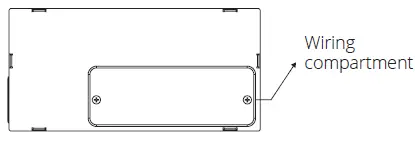
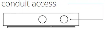
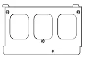
- Open wiring compartment

- Punch knockouts for wiring conduit access

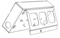
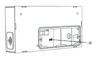
- Mounting the Driver :
Select a suitable location, which can provide adequate support for the weight of the driver.
Note: Install the LED Driver in a well-ventilated area free from explosive gases and vapors.
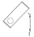
A. Mount the wall bracket
B. Position LED Driver at an angle over the bracket’s latches
C. Place LED Driver on the bracket latches
D. Align LED Driver on bracket
E. Install the supplied lock screw
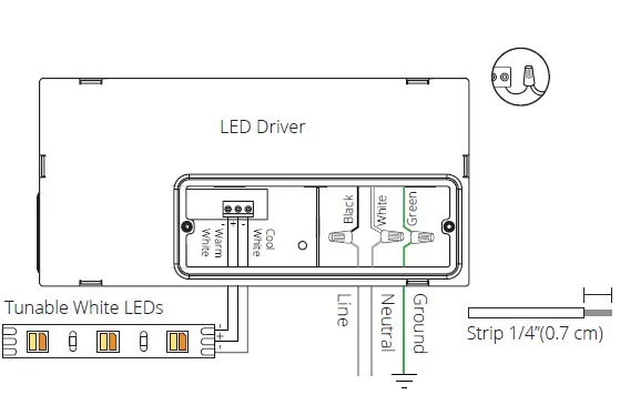
- Wire Connections :
With the power switched off, connect the wires according to the wiring diagram below.
Note: If you are connecting more than one wire to each terminal, it is recommended to form a pigtail connection.
WALL SWITCH INSTALLATION
Wallbox :
- A standard single-gang wallbox sized 3 x 2 x 2 ½ cm will service Wall Switch.
- Not compatible with multi or double Mud Rings.
- When using a retrofit gang box (cut in box) you might need to recess the ears.
Maximum Load :
| Input Voltage | Max Load |
| 120VA | 5A/600W |
Note: A maximum of 7 DriveTone Led drivers can be controlled with each DimTone.
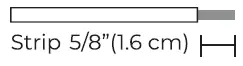
Step 1 : Preparing Wall Box Wires
- Make sure that the ends of the wires from the wallbox are straight (cut if needed).
- Strip the wire insulation from each wire. in the wallbox as shown here :

Step 2 : Wall Switch Wiring
Connect wires according to the wiring diagram below.
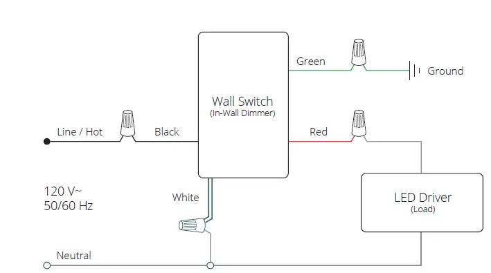
Wiring Description (Using wire connectors):
- Connect the green (or bare copper) wire from the wallbox to the green Wall Switch wire.
- Connect the line/hot wire from the wallbox to the black Wall Switch wire.
- Connect the black LED Driver wire to the red Wall Switch wire.
- Connect the white wire from the wallbox to the white LED Driver wire and the white Wall Switch wire.
Step 3: Mounting the Wall Switch
Mount Wall Switch into the wall box using the screws provided.
Do not use a drill screwdriver.
Step 4: Restore power
- Turn the power on at the circuit breaker.
- Verify 120V with a Voltmeter.

PAIRING
Before starting the pairing process, if you are installing more than one Wall Switch unit, all others must be switched off when you pair each unit.
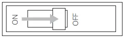
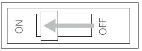
- Before starting, make sure both sliders are moved all the way up and Wall Switch is switched off.
- Switch the power on at the circuit breaker, and the LED Indicator will light up in green.
- Remove the sticker and turn on the Wall Switch paddle switch.
- The green LED Indicator will blink while pairing.
- After up to 15 seconds, your LED fixture should be paired with Wall Switch.
- To verify pairing is successful, move the sliders and ensure that the LEDs respond accordingly.
- If you encounter a problem at any stage of the pairing process, follow through the instructions under “Reset”.
Attach Wall Switch wall plate
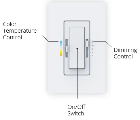
SYSTEM INSTALLATION COMPLETE!OPERATION
TROUBLESHOOTING
| Symptoms | Cause | Probable Action |
| Wall Switch LED Indicator blinking RED | Reset button is pressed while the wall switch is OFF | Turn ON the switch and press the reset button again |
| Wall Switch LED Indicator steady RED | Wall Switch is trying to perform pairing | Turn on the switch until paring is complete |
| Lights do not respond to Wall Switch | Breaker is OFF or tripped | Turn power On at Circuit breaker |
| Improper paring | Perform “Reset” | |
| Improper wiring | Make sure all wires are connected according to the wiring diagram | |
| Short circuit at the LED Driver output | Check LED driver output for short circuits | |
| Color temperature sliders control the opposite cover plate markings | Cold and warm wires reversed | Check the LED Driver output to the light and ensure they match the C and W marks |
| The wall switch is controlling the wrong lights (Only if multiple Wall Switch units are installed in the same location) | The Wall Switch was paired with the wrong LED Driver | Perform “Reset”. Make sure all other Wall Switches are turned off while pairing |
| Wall Switch / LED Driver Replacement | Any reason | Perform “Reset”. Make sure all other Wall Switches are turned OFF while paring |
RESET
The reset process matches between the Wall Switch and the
LED Driver/s connected to it. If you are replacing the Wall Switch or the LED Driver in an existing system, the reset process must be performed.
Important Note: if you are installing more than one Wall Switch unit, all others must be switched off when you pair each unit.
- Before starting, make sure both sliders are moved all the way up and the Wall Switch is switched off.
- Make sure that the power is turned on at the circuit breaker.
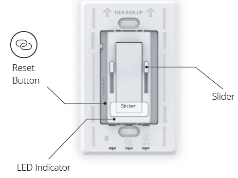
- Push the Reset button using a toothpick or similar object – see the location of the Reset button in the below diagram.
- The green LED Indicator will blink while pairing.
- After a maximum of 15 seconds, your LED fixture should be turned on indicating that the reset process has been completed.
- To verify pairing is successful, move the sliders and ensure that the LEDs respond accordingly.
- If you encounter a problem at any stage of the pairing process, please check troubleshooting symptoms or contact our support team.
Caution
To Reduce the Risk of Overheating And Possible Damage To Other Equipment, Do Not Install To Control A Receptacle, A Motor-Operated Appliance, Or A Transformer-Supplied Appliance.
FCC/IC Information
Radio Frequency Interference (RFI) (FCC 15.105)
This equipment has been tested and found to comply with the limits for Class B digital devices pursuant to Part 15 of the FCC Rules. These limits are designed to provide reasonable protection against harmful interference in a residential environment.
This equipment generates, uses, and can radiate radio frequency energy, and if not installed and used in accordance with the instruction manual, may cause harmful interference to radio communications. However, there is no guarantee that interference will not occur in a particular installation. If this equipment does cause harmful interference to radio or television reception, which can
be determined by turning the equipment off and on, the
user is encouraged to try and correct the interference by one or more of the following measures:
Reorient or relocate the receiving antenna.
- Increase the separation between the equipment and the receiver.
- Connect the equipment into an outlet on a circuit different from that to which the receiver is connected.
- Consult the dealer or an experienced radio/TV technician for help.
Modifications (FCC 15.21)
Changes or modifications to this equipment not expressly approved by (XXX add company name ) may void the user’s authority to operate this equipment.
More accessories on www.KlusDesign.com


