HUATO Multi-channel Handheld Thermocouple Temperature Data Logger User Guide

Introduction
Section 1 – Introduction
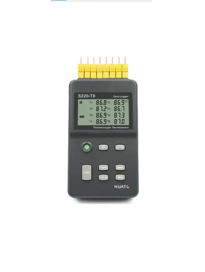
S220-T8 thermocouple temperature data logger is a kind of high precision instrument, developed and manufactured by HUATO company, which have pass all strict calibrations and professional testing via high precision instrument. Support 8 types thermocouples(K、J、E、T、R、S、N、B), including thermocouple temperature compensation function and can measure temperature from -200 to 1800°C.
Section 1.2 – Features
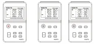
- LCD screen which can display data from 8 channels simultaneously.
- Switchable °C/°F t emperature units.
- Low battery indication.
- MAX, MIN and HOLD mode for all channels.
- Concise appearance, high precision, and reliable performance.
- Desktop and wall-mounted.
- Accompanied by powerful software with a concise interface.
- Match professional analysis software.
- Battery can work for 3 months. ( collect one data each minute, record one data 5 minutes)
Section 1.3 – Application
- Monitor temperature in factories, laboratories, storage house, refrigerators.
- Non-contact infrared surface temperature measurements in hard to reach areas such as heating and air conditioning ducts
There are no user serviceable parts inside your unit. Attempting to repair or service your
unit may void your warranty
Section 1.4 – Data Logger Model
| Model | Temperature Range | Resolution | Accuracy | Work Environment | Capacity of Records |
| S220-T8 | -200~1800℃ -328~3272℉ | 0.1℃ 0.1℉ | 0.8±2‰℃ | 0~80%RH 0~50℃ | 86,000 |
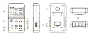
Section 1.5 – Temperature Data Logger Appearance
- LCD Screen
- Power On/Off
- LOG:Recording function button
- HOLD:Lock the Value.
- Screen Backlight
- °C/°F Switch
- TYPE:Switch for type of Sensor (K、J、E、T、R、S、N、B).
- MAX: Displaying maximum recorded value for all channels
- MIN: Displaying minimum recorded value for all channels
- USB & 9V DC power interface
- Wall-mount hole
- Battery Cover
- Back Stand
- Thermocouple Sensor Interface
Section 1.6 – Temperature Data Logger Screen
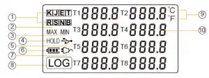
- Thermocouple Sensor Type: K、J、 E、T、R、S、N、B
- MAX: Logger running in maximum value mode.
- MIN: Logger running in minimum value mode.
- HOLD: Display is held.
- USB wire is connected between logger and computer
- Battery level
- DC Adapter (9V) connected
- LOG: logger is recording
- Temperature Unit: °C or °F
- Temperature display area
:Power ON/OFF
(1)When logger power is off, push this button will turn on the logger.
(2)When logger power is on, push this button will turn off the logger.
:Recording Function
(1)When logger power is on, press this button, the LCD screen will show “LOG”
a sign which indicates that the logger is recording data.
(2)Press the button for 3 seconds will put the logger in standby mode.
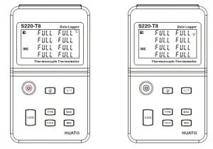
(3)The screen will display “FULL” symbol when storage space is full.
:Switchover Button of °C and °F
:Backlight Button
Press this button to open the backlight, and press again to close the light.
:Maximum Lock Button
Press this button once LCD shows “MAX” sign, which indicates that the logger is
recording maximum value for all channels; Press again to exit this mode.
:Minimum Lock Button
Press this button once LCD shows “MIN” sign, which indicates that the logger is
recording minimum value for all channels; Press again to exit this mode.
:Thermocouple Sensor Type Switch Button
Support 8 types of thermocouple sensors: J、K、E、T、R、S、N、B and press to
switch between different types of sensors.
:Measured Values Keeping Button
Press this button once, and the LCD screen will display “HOLD” sigh which indicates that the logger will keep the just measured value until the button is
pressed again.
Section 2 – Installation and Instruction
This section will explain how to use the software to upload, read, configure and synchronize the settings, how to turn on/off the logger & enter/exit the logging
mode, and how to delete and download the logging data.
Section 2.1 – Software Installation
2.1.1 – The Requirement of the Computer Hardware
- OS: Windows XP/Vista/8/10 (32/64-bit).
- CPU: 1.6GHz.
- Physical Memory: 512MB.
- Hard-drive Space: 4 GB.
- USB Port: 1.
2.1.2 – Install Driver & Software
Note : “If need to install Driver separately, please install 64-bit driver for Windows 64-bit computer & 32-bit driver for Windows 32-bit computer”.
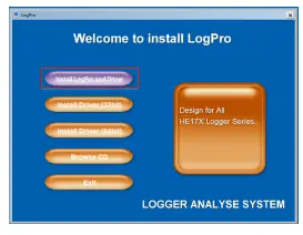
- Install LogPro Software and Driver together(Default Path: C:\OM-HL Logger).
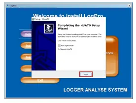
- Installation Steps: When entering the software, click the ‘Install LogPro and Driver’ (as below Pic ), and then click the ‘Next ’(5 times), click the ‘Install,’ click the ‘Finish.’
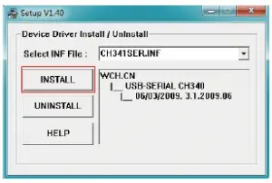
When entering the LogPro software interface, the installation driver software window will pop up. Click ‘Install,’ and the success of installation will be displayed.

LogPro installation page Default installation folder 
The successful installed Install driver
Section 2.2 – How to Read and Configure the Logger
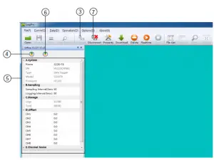
2.2.1 – Read and Configure the Logger’s Settings
- Turn on and Insert the data logger to the computer¹.
- Start LogPro software on the PC.
- From the toolbar select Connect.
- Load & Read the logger’s current settings.
- Configure the new settings.
- Sync the settings & time. (The PC time will be synchronized to the logger as well.) .
- From the toolbar select disconnect.
- Sync the Computer’s Data & Time to the Data Logger.
- Unplug the logger from the computer, and then the logger is in Standby mode.

- The Windows® operating system cannot handle USB devices being unplugged and plugged back too fast. When unplugging the logger, wait for about 5 seconds before plugging it in again. If you unplug and plug back a device too quickly, the computer may stop recognizing any USB devices on that port. If this happens, you will have to
restart the computer. This is a Windows® USB problem and is not related to Log Pro.
2.2.2 – Setting Parameters Description
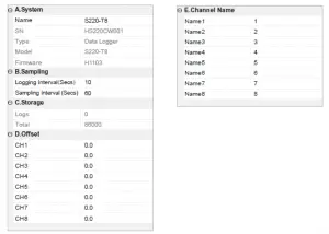
Setting Parameter | Text | Description |
| Name | English letters or numbers | Name of the logger |
| SN | 10 characters | Must be the same as the one in the label of logger |
| sampling Interval (secs) | Number from 1 to 240 | Sampling frequency in LCD screen |
| Logging Interval (secs) | Number from 2 to 86400 | Logging frequency |
| Logs | Number from 0 to 86000 | The count of records in the memory |
| Total | Number 86000 | The total capacity of the logger’s storage |
|
Offset | Calibration mode: For example, pls fill in 1.5 if the displayed temperature is higher than the actual temperature of 1.5 ℃; fill in -1.5 if the displayed temperature is lower than the actual temperature of 1.5 ℃. If you need to adjust the humidity, do the same, the number field is -100~100. |
Input positive number to decrease the value.input negative number to increase the value. |
| Channel Name | English Letters or Numbers | Name of each channel |
| Calibrate the logger: The logger is factory calibrated to an accuracy given in the device specifications. However, there may be times when you wish to adjust the calibration of your logger. Logpro provides you with the ability to perform a single point offset calibration. This calibration can be used to increase the accuracy of the logger for a restricted data range. | ||
Turn On the Logger – Push “ON / OFF” Button for pressing the switch button momentaril then LCD display is on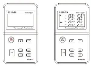
Start Logging – When the Logger is on and on stand-by (LCD does not have “LOG” logo display), press “LOG ” button, LCD has “LOG” logo display, now the logger start logging and storing data.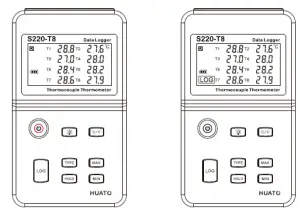
Stop Logging When the Logger is on logging, long press “LOG”, LCD display countdown time, loosen “LOG” but ton when countdown time finished, then the
instrument switch from logging to standby state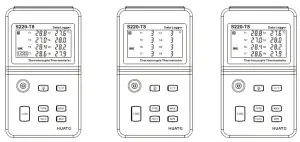
Turn Off the Logger – Push the“ON / OFF” Button for short pressing then LCD display is off.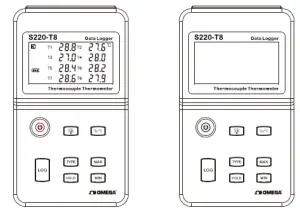
LOG Full -The device won’t record data while the memory is full, that you have to download the data and delete it by Logpro software, then device can record again.
Switchable °C or °F – Press the “°C/°F” key shortly When instrument records data in degrees (the LCD displays the °C symbol), and the instrument switches to Fahrenheit as
the recording unit display data (the LCD displays the °F symbol). It Can Switch back and forth between °C and °F as you Press this button repeatedly.
Section 2.4 – Download the Logging Data
10. Insert the data logger into the computer.
11. Start LogPro software on the PC.
12. From the toolbar select Connect.
13. From the toolbar select Download
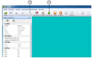
Once the data is downloaded from the logger to the PC, the log graph will be displayed.
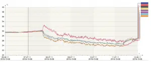
Tips:Press and hold the left mouse button to drag a box, when the left mouse button is released, the graph will be redrawn with the data in the selected rectangle area. Click
right button, and then the graph will be redrawn with all the data in the logs file.
Section 2.5 – View Data Sheet
Click “Data List” button on the toolbar, and then the data listing window is shown below.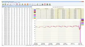
The data pane lists the data samples collected by the logging device. The column width of each column is adjustable by using the left mouse button
and dragging the column to the desired width.
Section 2.6 – Exporting Logs from LogPro
 Export data list to an Excel file.
 Export data list to a PDF file.
 Export graph to a BMP file.
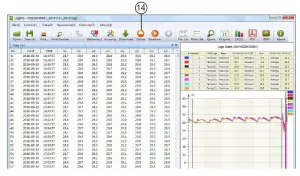
Section 2.7 – Delete Records in the Logger
14. From the toolbar select Delete
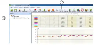
Section 2.8 – Check the Save File in File list
15. From the toolbar select File List.
16. Click to open the file.
- Double click left mouse button, then the selected file is opened.
- Click right mouse button, a popup menu is shown as below, you can rename or delete or log file.
- The saved file is saved in the LogPro software’s installation path in the PC’s hard driver.

Section 3 – Attention
- Plastic shell is ABS, should be retardant, not resistant to acid and alkali.
- If repair is needed, only authorized technician can do the repair.
- The instrument configuration by 9V block battery is not rechargeable.
- USB power supply (4.8V) cannot let the Data Logger work.
Section 4.1 – LCD Screen Dim
Insufficient battery or the environment temperature is too low or too high. Solution: In the case of insufficient battery, please replace the battery. If results
from environment temperature, please immediately take the logger out of the environment.
Section 4.2 – Data & Time Error
Reason:
- The Battery level is low.
- The Data Logger is not synchronous properties, before start recording. Solution:
- Replace the battery.
- Please sync the properties, before start recording.
Section 4.3 – Software “Runtime Error”
Reason:
- OS forbid software creating files. Solution:
- Run the program (software) as an administrator.
- Install software in D or E drive if available.
- A data logger name cannot contain any of the following characters: \ / : * ? “ < > |
- Software’s installation path cannot include Chinese character or garbage character.
Section 4.4 – Check COM Port Number
Press “Win” + “R” in keyboard -> Run “devmgmt.msc” to Open “Device Manager” in Windows-> Expand “Ports (COM & LPT)” -> “USB-serial CH340
(COM No.)” is the Data Logger.


