CiAODA SRF-M810 UHF Radio Frequency Identification Module
Product Overview
The SRF-M810 is a long-range radio frequency identification (RFID) reader that operates on the 900MHz (UHF band). It is compatible with various operating bands specified by individual countries and complies with all standard protocols defined in ISO18000-6C (EPC GEN2).
Product Features
- Small and powerful performance
- 30 dBm RF power output
- Including TTL232 communication interface can remote and back-end equipment to transfer code and control code.
- Read up 750 tags/second
- Avoid the interference of other radio frequencies with the look-up table frequency-hopping spread spectrum (FHSS)
- Pass FCC, NCC certification
- Support external sensors and controllers
- API under Windows operating system for shorten application development time
- The complete TTL232 instruction format facilitates the expansion of device functional integrity
Recommended Uses
The SRF-M810 is recommended for use in:
- Driveway control and management/personnel access control and management of residential buildings, buildings, and communities
- Industrial related management and control
- Elevator control and management
- Logistics related management
- Asset management
- Security monitoring
- Handheld devices and scanners
Product Usage Instructions
- Install the SRF-M810 in the desired location according to the installation instructions provided in the user manual.
- Connect the SRF-M810 to the remote and back-end equipment using the TTL232 communication interface.
- Use the API under Windows operating system for application development or follow the complete TTL232 instruction format to expand device functional integrity.
- Power on the SRF-M810.
- Place RFID tags within range of the reader to read up to 750 tags per second.
- External sensors and controllers can be connected to the SRF-M810 to support various applications.
SRF-M810 UHF Radio Frequency Identification (RFID)
Module User’s Manual
Overview
As a long-range radio frequency identification (RFID) reader, the SRF-M810 is a 900MHz ( UHF band ) UHF RFID reader operable at various operating bands specified by individual countries. It also complies with all standard protocols defined in ISO18000-6C (EPC GEN2)。
Features
- Small and powerful performance
- 30 dBm RF power output
- Including TTL232 communication interface can remote and back-end equipment to transfer code and control code.
- Read up 750 tags/second
- Avoid the interference of other radio frequencies with the look-up table frequency-hopping spread spectrum (FHSS)
- Pass FCC ,NCC certification
- Support external sensors and controllers
- API under Windows operating system for shorten application development time
- The complete TTL232 instruction format facilitates the expansion of device functional integrity
Recommended uses:
- Driveway control and management / personnel access control and management of residential buildings,buildings,and communities
- Industrial relate management and control
- Elevator control and management
- Logistics related management
- Asset management
- Security monitoring
- Handheld devices and scanners
FCC
FCC ID : 2A3LY-SRFM810
Federal Communications Commission (FCC) Statement
This device complies with Part 15 of the FCC Rules. Operation is subject to the following two conditions:
- This device may not cause harmful interference and
- This device must accept any interference received, including interference that may cause undesired operation.
Federal Communications Commission (FCC) Statement 15.105(b)
This equipment has been tested and found to comply with the limits for a Class B digital device, pursuant to part 15 of the FCC rules. These limits are designed to provide reasonable protection against harmful interference in a residential installation.
This equipment generates, uses and can radiate radio frequency energy and, if not installed and used in accordance with the instructions, may cause harmful interference to radio communications. However, there is no guarantee that interference will not occur in a particular installation. If this equipment does cause harmful interference to radio or television reception, which can be determined by turning the equipment off and on, the user is encouraged to try to correct the interference by one or more of the following measures:
- Reorient or relocate the receiving antenna.
- Increase the separation between the equipment and receiver.
- Connect the equipment into an outlet on a circuit different from that to which the receiver is connected.
- Consult the dealer or an experienced radio/TV technician for help.
15.21
You are cautioned that changes or modifications not expressly approved by the part responsible for compliance could void the user’s authority to operate the equipment.
FCC RF Radiation Exposure Statement:
- This Transmitter must not be co-located or operating in conjunction with any other antenna or transmitter.
- This equipment complies with FCC RF radiation exposure limits set forth for an uncontrolled environment. This equipment should be installed and operated with a minimum distance of 20 centimeters between the radiator and your body.
List of applicable FCC rules
This module has been tested and found to comply with the following requirements for Modular Approval.
- 15.249 Operation within the bands 902.75-927.25 MHz.
RF exposure considerations
In the end product, the antenna(s) used with this transmitter must be installed to provide a separation distance of at least 20cm from all persons and must not be co-located or operation in conjunction with any other antenna or transmitter except in accordance with FCC multi-transmitter product procedures. User and installers must be provided with antenna installation instructions and transmitter operating conditions for satisfying the RF exposure compliance.
The OEM integrator has to be aware not to provide information to the end user regarding how to install or remove this RF module in the user’s manual of the end product which integrates this module. The end user manual shall include all required regulatory information/warning as shown in User manual.
Antennas
The following external antenna type have been approved for use with this radio transmitter.
| Antenna Type | Freq. (MHz) | Max. Peak Antenna Gain (dBi) |
| Patch | 902~908 | 5.24 |
Label and compliance information
Any device incorporating this module must include an external, visible, permanent marking or label which states: “ Contains FCC ID: 2A3LY-SRFM810 ”.
Information on test modes and additional testing requirements
This device uses various test mode programs for test set up which operate separate from production firmware. Host integrators should contact the grantee for assistance with test modes needed for module/host compliance test requirements.
Additional testing, Part 15 Subpart B disclaimer
The modular transmitter is only FCC authorized for the specific rule parts (i.e., FCC transmitter rules) listed on the grant, and that the host product manufacturer is responsible for compliance to any other FCC rules that apply to the host not covered by the modular transmitter grant of certification.
The final host product still requires Part 15 Subpart B compliance testing with the modular transmitter installed.
Product specifications
| DC POWER | 5 V |
| Current Consumption | Max. 1500mA |
| RFID Protocol Support | EPC Global Gen2V2(ISO 18000-63 ) with DRM |
| Antenna | 2 Port |
| Antenna Connector | Ipex 1 |
| Antenna Setting | GPIO/Instruction |
| Antenna Impedance | 50 ohm U.FL. |
| Antenna Return Loss | 10dB min |
| Control Interface | UART |
| Frequency | 922-928 MHz/Taiwan,902.75-927.25 MHz/FCC,865-868 MHz/CE |
| RF POWER | 30 dBm |
| Max Read Rate | Over 750PCS per second with Direct Mode |
| Query | Static/Dynamic QUERY |
| Max Tag Read Distance | Over 9 meter with 5.24dBi Antenna |
| Receive Sentivity | -89 dBm |
| Operating Temp. | -20℃ ~ +60℃ |
| Storage Temp. | -20℃ ~ +85℃ |
| Humidity | 5-90% |
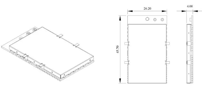
| Dimension (L*W*H) | 45.7mm L x 26.2mm W x 4mm H |
| Weight | |
| SDK Support | DLL with C, Demo Software & Source Code with C# |
Pin Description
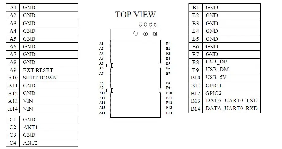
| Pin | Pin Name | Description |
| A1 | GND | Ground pin for main reference ground |
| A2 | GND | Ground pin for main reference ground |
| A3 | GND | Ground pin for main reference ground |
| A4 | GND | Ground pin for main reference ground |
| A5 | GND | Ground pin for main reference ground |
| A6 | GND | Ground pin for main reference ground |
| A7 | GND | Ground pin for main reference ground |
| A8 | GND | Ground pin for main reference ground |
| A9 | EXT RESET | Reserved |
| A10 | SHUT DOWN | Shut down RF module |
| A11 | GND | Ground pin for main reference ground |
| A12 | GND | Ground pin for main reference ground |
| A13 | VIN | Power supply input |
| A14 | VIN | Power supply input |
| Pin | Pin Name | Description |
| B1 | GND | Ground pin for main reference ground |
| B2 | GND | Ground pin for main reference ground |
| B3 | GND | Ground pin for main reference ground |
| B4 | GND | Ground pin for main reference ground |
| B5 | GND | Ground pin for main reference ground |
| B6 | GND | Ground pin for main reference ground |
| B7 | GND | Ground pin for main reference ground |
| B8 | USB_DP | Reserved |
| B9 | USB_BM | Reserved |
| B10 | USB_5V | Reserved |
| B11 | GPIO1 | Function define. Refer to user guide |
| B12 | GPIO2 | Function define. Refer to user guide |
| B13 | UART0_TXD | UART0 data transmitter output pin |
| B14 | UART0_RXD | UART0 data receiver input pin |
| Pin | Pin Name | Description |
| C1 | GND | Ground pin for main reference ground |
| C2 | ANT1 | Ipex 1 connector for antenna 1 port |
| C3 | GND | Ground pin for main reference ground |
| C4 | ANT2 | Ipex 1 connector for antenna 2 port |
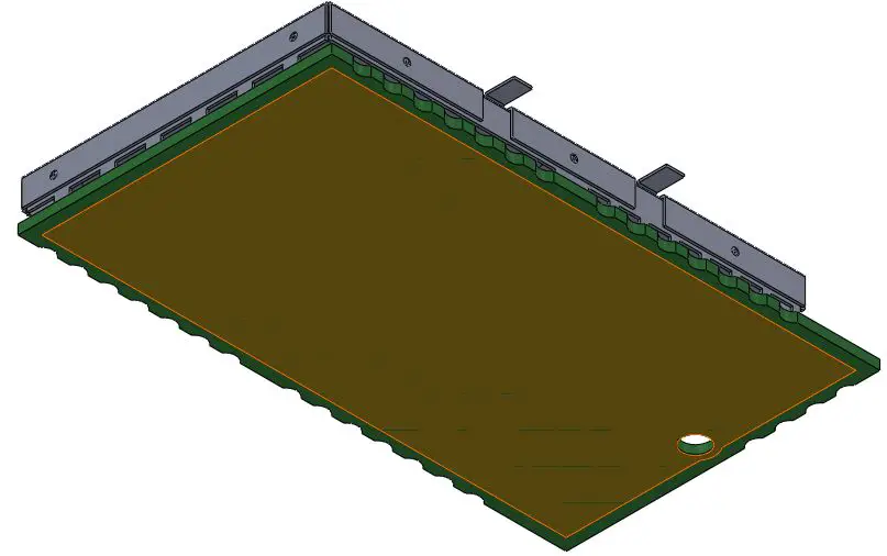
Layout Guide
- In the bottom of the RF module exposed copper, coated with thermal paste

- Cooling Recommendations on layout

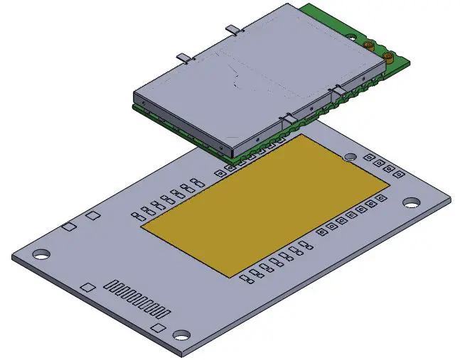
Landing Pattern Recommendation
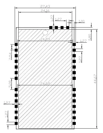
Dimension
Warranty Coverage
- The product’s warranty against defects in materials and workmanship under normal use for a period of ONE YEAR from the date of purchase by the original user of the Product. This warranty is non-transferable.
- If the product prove to be defective within the warranty period, Szok will repair the product defect at no charge, using new or refurbished replacement parts to proper operating condition.
This Warranty Does Not Apply To:
- Damage from flood, fire, earthquake, natural disaster or other external causes.
- If the defects are due to damage caused by accident, misuse, tampering, unauthorized modification or human negligence, such as parts lost, loose or lack of care and physical abuse to the product (e.g, scratches, dents, or cracks).
- Damage caused by operating the product outside the permitted, intended uses described by Szok, or service(including upgrades and expansions) performed by unauthorized representative.
- If any serial number or logo affixed has been altered, removed, duplicated or defaced from Szok Product.


