
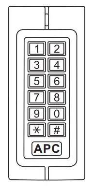
APC KP1-C Slimline Vandal Resistant Keypad with EM card Reader
Introduction
The APC-KP1-C Is an IP 65 rated keypad with a built in card reader access control system. The APC-KP1-C can store up to 2000 Users. It supports three access modes; card, card plus PIN and card or PIN. Other features that are built in such as Anti-vandal, alarm, exit button, safe mode, wiegand input/output, etc.
Technical Specifications
| Features | Description |
| Appearance | Metal case, anti-explosion and anti-tamper |
| Waterproof | IP65 |
| Input voltage | DC: 12-24V AC: 12-18V |
| Capacity(max) | 2000 Users |
| PIN | 4-8 digits. Not related to the card. |
| Master card | Add/delete user |
| As reader | Support Wiegand 26bits, PIN wiegand output is virtual number. |
| Connect external reader | Can connect any EM/HID/IC readers with wiegand 26 output |
| Connect high power alarm | External current of the alarm ≥3A |
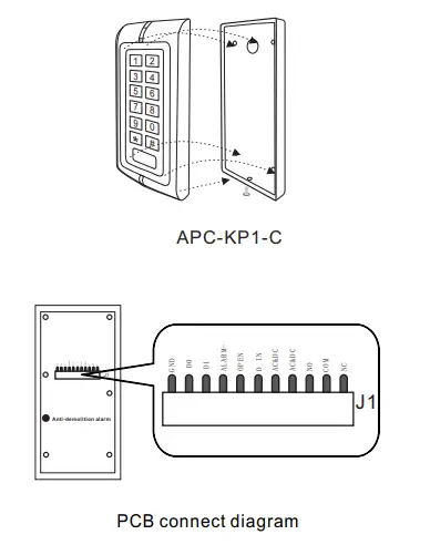
Installation Procedure
Installation and Fixation
- Drill hole on the wall according to the back cover of the keypad.
- Feed the cable through cable hole and connect to the related cable. For the un-used wires please cut to unequal lengths and insulate with electrical tape.
- Fix back cover on the post using the supplied screws.
- After wiring connections are completed fix the keypad front cover to the back cover.
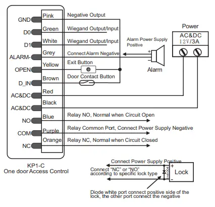
Wiring
| Function | Color | Description |
| D0 | Green | Wiegand 26 output/input |
| D1 | White | Wiegand 26 output/input |
| ALARM- | Grey | Alarm Negative |
| OPEN | Yellow | Request to Exit Button |
| D_IN | Brown | Door Contact |
| AC&DC | Red | 12V AC&DC Regulated Power Input |
| AC&DC | Black | 12V AC&DC Regulated Power Input |
| NO | Blue | Relay NO |
| COM | Purple | Relay COM |
| NC | Orange | Relay NC |
| GND | Pink | Negative |
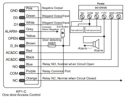
Connection Diagram
Common power supply
Special Power Supply
Administrator Operation
To Reset to Factory Default
To reset to factory default, power off, press “*” &hold whilst powering on, release “*” when you hear the two beeps and the LED turns orange. Now the keypad needs to authorize the master add and delete card. Swipe the Master ADD first then the Master DELETE second. Now the LED will turn RED indicating success. If no cards are swiped within 10 seconds it will skip the Master Card Authorization.
Note: Resetting to factory default only resets the Programming Code and Master Cards.
Enter into Programming Code
Press * Master code # 888888 is the default factory master code.
Note: Below 3 to 11 items all operation need in programming mode.
Change Master Code
Press 0 New code # New code #
Note: The master code can be any 6 digits, please store this number carefully.
To add users
- To add card users automatically. Press 1 Read card1 Read card2 … #
The range of ID number is any number between 1~2000. - To add card users manually
Press 1 ID number 1# read card1 ID number 2# read card2 … #
First # is to “confirm”and the second # is the end of the current settings. Press * will exit the current operation. - To add no-card users
Press 1 ID number 1# PIN 1 ID number 2# PIN 2 … #
The PIN of is 4-8 digits any number.(exception of 1234) - To add card users synthetically
Press 1 read card1 ID number 1# read card2 ID number 2# PIN# … # - To add users by manager card
Manager add card Swipe add user card continuously Manager add card
That is exit add users settings - To add consecutive card users
Press 5 ID number # 8 digits number 1 # Card number #.
Mark: The quantity of cards cannot not exceed 2000.The ID number must be continuous vacant number.
To delete users
- Auto Delete
Press 2 Read card1 Read card2 … # - Manual Delete
Press 2 ID number1# … # - Synthetical Delete
Press 2 Read card1 ID number1# … # - Delete all users
Press 2 0000 # - To delete User by Manager Delete Card
Manager delete card Swipe deletes user card continuously Manager delete card That is exit delete users settings.
Door Open mode settings
- Open by cards:
Press 3 0 # - Open by cards+PIN
Press 3 1 # - Open by cards or PIN(Factory default)
Press 3 2 # - Door relay time settings
Press 4 0~99 #
Marks: The door relay time is between 0~99 seconds, the factory default setting is 5 seconds.
Door open detection settings
- To disable door open detection. (Factory default)
Press 6 0 # - To enable door open detection
Press 6 1 # - When this function is used there are two scenarios: If the door is opened normally but not closed after 1 minute the inside buzzer will beep automatically to remind people to close the door and continue for 1 minute before switching off automatically.
- If the door is forced open, the inside buzzer and alarm output will both operate.
Security Mode settings
- Normal status:(Factory default )
Press 7 0 # - Keypad Lockout
Press 7 1 #
If there are 10 invalid cards or 10 incorrect PIN numbers in a 10 minute period either the keypad will lockout for 10 minutes. - Alarm Output
Press 7 2 #
If there are 10 invalid cards or 10 incorrect PIN numbers in a 10 minute period either the outside buzzer and alarm output will both operate.
Alarm output time
Press 9 1~3 #
Factory default is 1 minute
User Settings
- Cards users change the PIN
* Read Card Old PIN # New PIN # Repeat New PIN #
Can be 4-8digits.The PIN cannot be changed to “1234” - No card users the PIN
* ID number # Old PIN # New PIN # Repeat New PIN #
Can be 4-8digits.The PIN cannot be changed to “1234” - Open door by users card
Read Card If it is valid. the door will open. - Open door by PIN
Users PIN # If the PIN is correct, the door will open. - Open door by users card+PIN
Read Card Users PIN #
If the card and PIN is correct, the door will open. - To remove the alarm
The inside buzzer and alarm output will both operate.
Read valid card or press Master Code # to reset the Door Forced Open warning. - Close the door forced warning
Close the door or Read valid card or Master Code # to reset the Door Forced warning.
Sound and Light indication
| Operation Status | Red Light | Green Light | Buzzer |
| Stand by | Slow flash | Off | |
| Press keypad | Short Ring | ||
| Operation successful | Off | Bright | Ring… |
| Operation failed | 3 Short Rings | ||
| Enter into programming mode | Bright | Off | Ring… |
| In the programming mode | Bright | Bright |
| Exit from the programming mode | Slow flash | Off | Ring… |
| Open the door | Off | Bright | Ring… |
| Alarm | Quick flash | Off | Alarm |
Specifications
| Operating Voltage | DC:12~24V AC:12-18V |
| Idle Current | 35±5mA |
| Active Current | <80mA |
| Card Reading Distance | 3~6 cm |
| Operating Temperature | -40~60 |
| Lock Output Load | 2A |
| Alarm Output Load | 3A |


