FORTINET FortiGate Rugged 70F Series Integrated Security for Industrial Control Systems
Before you begin
Register your device to access FortiGuard updates, cloud management, firmware upgrades, technical support, and warranty coverage.
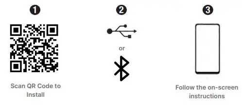
FortiExplorer App
Rapidly provision, deploy, and monitor Security Fabric components including FortiGate and FortiWiFi devices from your mobile. Download now for free.
Scan the QR Code or visit: https://links.fortinet.com/fortiexplorer/downloads
This guide covers: FGR-70F, FGR-70F-3G4G December 20, 2022 Copyright© 2022 Fortinet, Inc. All rights reserved. Fortinet®, FortiGate®, FortiCare® and FortiGuard®, and certain other marks are registered trademarks of Fortinet, Inc., in the U.S. and other jurisdictions, and other Fortinet names herein may also be registered and/or common law trademarks of Fortinet. All other product or company names may be trademarks of their respective owners. Performance and other metrics contained herein were attained in internal lab tests under ideal conditions, and actual performance and other results may vary. Network variables, different network environments and other conditions may affect performance results. Nothing herein represents any binding commitment by Fortinet, and Fortinet disclaims all warranties, whether express or implied, except to the extent Fortinet enters a binding written contract, signed by Fortinet’s General Counsel, with a purchaser that expressly warrants that the identified product will perform according to certain expressly-identified performance metrics and, in such event, only the specific performance metrics expressly identified in such binding written contract shall be binding on Fortinet. For absolute clarity, any such warranty will be limited to performance in the same ideal conditions as in Fortinet’s internal lab tests. In no event does Fortinet make any commitment related to future deliverables, features or development, and circumstances may change such that any forward-looking statements herein are not accurate. Fortinet disclaims in full any covenants, representations, and guarantees pursuant hereto, whether express or implied. Fortinet reserves the right to change, modify, transfer, or otherwise revise this publication without notice, and the most current version of the publication shall be applicable. For Product License Agreement / EULA and Warranty Terms, visit https://www.fortinet.com/content/dam/fortinet/assets/legal/EULA.pdf
The Essentials
Default LogAins
- https://192.168.1.99 Username: admin Password: leave blank
Admin Guide
For a detailed Getting Started guide, setup, configuration information, refer to the Admin Guide on https://docs.fortinet.com/product/fortigate
Customer Service
For contracts, licensing, product registration and account management, contact FortiCare Support at https://www.fortinet.com/support/contact
Self-service Resources
Access our knowledge base, forums, videos and technical experts at https://www.fortinet.com/support/support-services/forticare-support
Thank you for choosing Fortinet
Package Contents
FortiGate Rugged 70F Series FGR-70F, FGR-70F-3G4G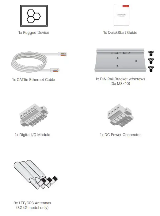
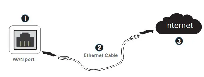
Setup
Unpack the box, power the device and choose one of the following options:
FortiExplorer
Note: Enable Bluetooth on your mobile device for BLE or connect your mobile’s USB cable into the device
GUI
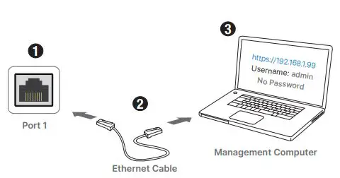
Note: Configure the management computer with IP 192.168.1.x and subnet 255.255.255.0
CLI
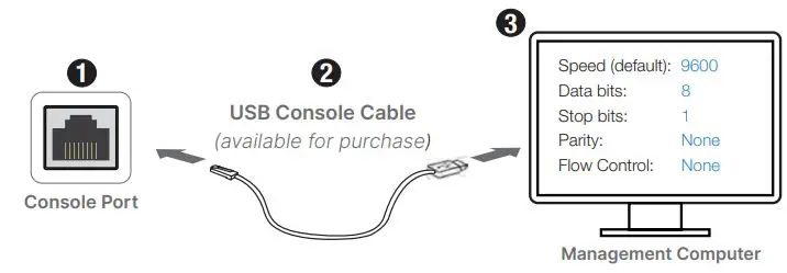
Note: For a detailed CLI guide, visit docs.fortinet.com
FortiGate Cloud
Note: Browse to forticloud.com and follow the on-screen instructions
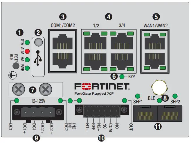
Front – FGR-70F
STA
 Green: Operating normally
 Flashing Green: Device resetting
 Red: Device error
ALM
- Red: Major alarm detected
 Amber: Minor alarm detected
 Off: No alarm detected
HA
- Green: HA enabled (normal)
- Red: HA enabled (failover)
- Off: HA disabled
PWR
- Green: Power detected
- Off: Power not detected
BLE/RST Activates BLE management or restores to factory default
- USB (USB 2.0) Server port
- COM1 (RJ45) Console (Top Port) COM2 (RJ45) Serial Data (Bottom Port)
Ports 1 to 4 (RJ45)
 Green: Connected at 1000Mbps
 Amber: Connected at 100Mbps
 Off: No link established or connected at 10Mbps
- Green: Link established, no activity
 Flashing Green: Data activity
- Off: No link established

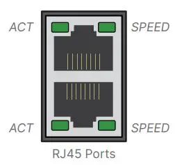
WAN1 & WAN2 Ports (RJ45)
- Green: Connected at 1000Mbps
- Amber: Connected at 100Mbps
- Off: No link established or connected at 10Mbps
- Green: Link established, no activity
- Flashing Green: Data activity
- Off: No link established
Bypass Status
- Green: PHY mode
- Red: Bypass mode
Earth Ground optional connection
BLE
 Blue: BLE connected
 Flashing Blue: BLE active
- Off: BLE off
Power Terminals (DC1 & DC2) Redundant failover, 12V to 125V DC, 2A Max
(Note: Alarm disabled by default in the OS. Wire range is 30 – 16 AWG)
- Green: Power detected
- Red: Alarm is on; no power detected
- Off: No power detected
Digital I/O Connector software-defined alarms. See page 17 for details.
Input (IN1 & IN2)
- Green: Alarm defined, not detected
- Red: Alarm detected
- Off: Alarm not defined
Output(OUT)
- Green: Alarm defined, not detected
 Flashing Red: Major output alarm
- Red: Minor output alarm
- Off: No output alarm detected
SF P 1 & S F P 2 ( S F P )
- Green: Connected at 1000Mbps
- Flashing Green: Data activity
- Off: No link established
Front – FGR-70F-3G4G
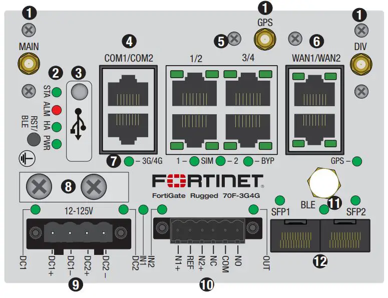
Antenna Connection (3x SMA) WWAN and GPS antenna connections
STA
- Green: Operating normally
- Flashing Green: Device resetting
- Red: Device error
ALM
- Red: Major alarm detected
- Amber: Minor alarm detected
- Off: No alarm detected
HA
- Green: HA enabled (normal)
- Red: HA enabled (failover)
- Off: HA disabled
PWR
- Green: Power detected
- Off: Power not detected
BLE/RST Activates BLE management or restores to factory default
- USB (USB 2.0) Server port
- COM1 (RJ45) Console (Top Port)
- COM2 (RJ45) Serial Data (Bottom Port)
Ports 1 to 4 (RJ45)
- Green: Connected at 1000Mbps
- Amber: Connected at 100Mbps
- Off: No link established or connected at 10Mbps
- Green: Link established, no activity
- Flashing Green: Data activity
- Off: No link established
WAN1 & WAN2 Ports (RJ45)
- Green: Connected at 1000Mbps
- Amber: Connected at 100Mbps
- Off: No link established or connected at 10Mbps
- Green: Link established, no activity
- Flashing Green: Data activity
- Off: No link established
3G4G & Bypass Status 3G/4G
- Green: 4G service on
- Amber: 3G service on
- Off: 3G/4G service off
SIM 1 & 2
- Green: SIM active
- Off: SIM not active
BYP
- Green: PHY mode
- Red: Bypass mode
GPS
- Green: GPS enabled
- Off: GPS disabled
Earth Ground optional connection
Power Terminals (DC1 & DC2) Redundant failover, 12V to 125V DC, 2A Max
(Note: Alarm disabled by default in the OS. Wire range is 30 – 16 AWG)
- Green: Power detected
- Red: Alarm is on; no power detected
- Off: No power detected
Digital I/O Connector software-defined alarms. See page 17 for pinout.
Input (IN1 & IN2)
- Green: Alarm defined, not detected
- Red: Alarm detected
- Off: Alarm not defined
Output(OUT)
- Green: Alarm defined, not detected
- Flashing Red: Major output alarm
- Red: Minor output alarm
- Off: No output alarm detected
BLE
- Blue: BLE connected
- Flashing Blue: BLE active
- Off: BLE off
SFP1 & SFP2 (SFP)
- Green: Connected at 1000Mbps
- Flashing Green: Data activity
- Off: No link established
MICRO SD Slot – FGR-70F Series
WARNING: Power off device to install/uninstall an SD card as the FGR-70F Series does not support hot-swapping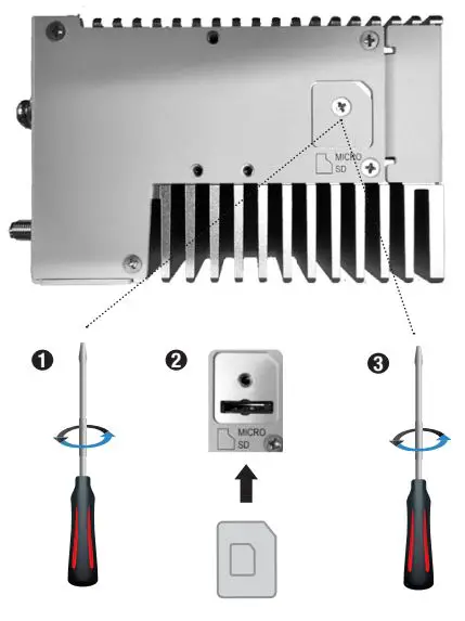
SIM Slots – FGR-70F-3G4G
NOTE: Refer to the Admin guide on docs.fortinet.com for wireless WAN configuration information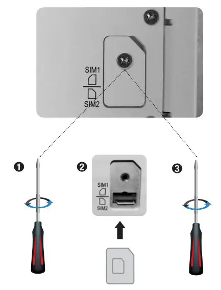
NOTE: SIM1 is primary, SIM2 is secondary
Dimensions
The FGR-70F and FGR-70F-3G4G share the same chassis dimensions. 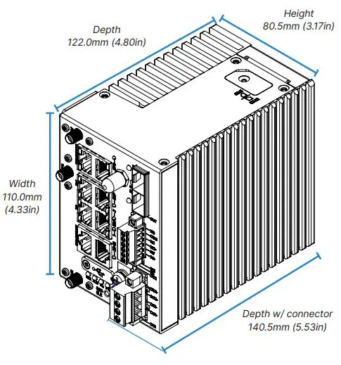
For the FGR-70F-3G4G, the antenna dimensions are shown below.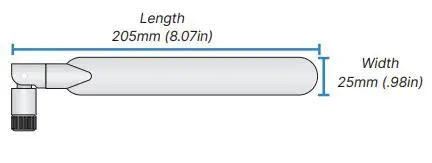
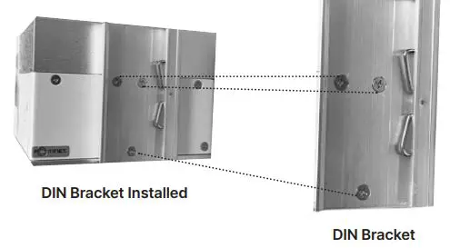
DIN Installation
The FGR-70F Series mounts on the side or rear of the device using the provided screws.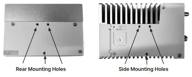
- Secure the bracket to the device

- Mount the device to the rail


Power Installation
Warnings
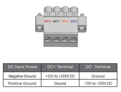
- The dual redundant DC input supports negative ground (+12V to +125V DC) and positive ground (-12V to -125V DC)
- DC1+ and DC2+ are the high voltage potential pins and DC1- and DC2- are the lower voltage potential pins
- Do not connect DC+ terminal to a lower voltage potential than DC- terminal
- The voltage between a DC+ and DC- must be +12V to +125V DC
- Consult a professional electrician to install the device and determine a suitable wire gauge and length
- The DC terminal block wire gauge maximum is 12 AWG; the minimum is 30 AWG
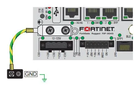
- Optional but recommended, connect earth ground using the lug plate or grounding screw
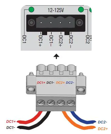
- Connect DC1+ or DC2+ on the device terminal block to the DC power source, then connect the negative DC1- or DC2- on the terminal block

- Optional – Secure the earth ground terminal of the device to chassis ground or earth ground

- Insert the wired power connector into the terminal block on the device

OPTIONAL: The FGR-70F Series has optional dual DC inputs for failover redundancy. If a DC input fails, the second input will supply power.
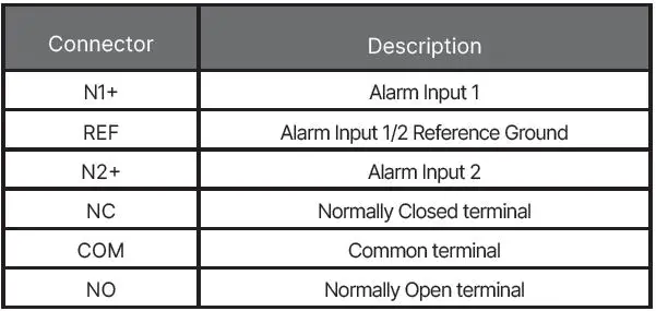
Digital I/O Connector
Refer to the Admin Guide for configuration settings.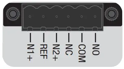
BIOS Options
The FortiGateRugged 70F provides an option in the BIOS menu to set the CPU speed from high-performance mode (default) to low power mode.
When prompted during bootup, press any key to enter the BIOS
- Type F to set the CPU frequency, then follow the onscreen instructions
- Press Q twice to exit and continue the bootup process
NOTE: See the admin guide on docs.fortinet.com for more information
Cautions and Warnings
Environmental specifications
- Ambient operating temperature: -40°C to 75°C Refer to specific Product Model Data Sheet for Environmental Specifications (Operating Temperature, Storage Temperature, Humidity, and Altitude)
Safety
Warning: Equipment intended for installation in Restricted Access Location.
Grounding — To prevent damage to your equipment, connections that enter from outside the building should pass through a lightning / surge protector, and be properly grounded. Use an electrostatic discharge workstation (ESD) and/or wear an anti-static wrist strap while you work. In addition to the grounding terminal of the plug, on the back panel, there is another, separate terminal for earthing.
This product has a separate protective earthing terminal provided on the back of the product in addition to the grounding terminal of the attachment plug. This separate protective earthing terminal must be permanently connected to earth with a green with yellow stripe conductor minimum size # 14 AWG and the connection is to be installed by a qualified service personnel.
Regulatory Notices
Federal Communication Commission (FCC) – USA
This device complies with Part 15 of the FCC Rules. Operation is subject to the following two conditions:
- this device may not cause harmful interference, and
- this device must accept any interference received; including interference that may cause undesired operation.
This equipment has been tested and found to comply with the limits for a Class A digital device, pursuant to Part 15 of the FCC Rules. These limits are designed to provide reasonable protection against harmful interference when the equipment is operated in a commercial environment. This equipment generates, uses, and can radiate radio frequency energy, and if it is not installed and used in accordance with the instruction manual, it may cause harmful interference to radio communications. Operation of this equipment in a residential area is likely to cause harmful interference, in which case the user will be required to correct the interference at his own expense.
WARNING: Any changes or modifications to this product not expressly approved by the party responsible for compliance could void the user’s authority to operate the equipment.
This equipment complies with FCC radiation exposure limits set forth for an uncontrolled environment. This equipment should be installed and operated with minimum distance 20cm between the radiator and your body. This transmitter must not be co-located or operating in conjunction with any other antenna or transmitter.
Industry Canada Equipment Standard for Digital Equipment (ICES) – Canada
CAN ICES-003 (A) / NMB-003 (A) This digital apparatus does not exceed the Class A limits for radio noise emissions from digital apparatus set out in the Radio Interference Regula¬tions of the Canadian Department of Communications.
Innovation, Science and Economic Development (ISED) – Canada
This device contains licence-exempt transmitter(s)/receiver(s) that comply with Innovation, Science and Economic Development Canada’s licence-exempt RSS(s). Operation is subject to the following two conditions:
- This device may not cause interference.
- This device must accept any interference, including interference that may cause undesired operation of the device.
This device and it’s antennas(s) must not be co-located or operating in conjunction with any other antenna or transmitter except in accordance with IC multi-transmitter product procedures.
- Antenna type
- Monopole
- Connector
- I-PEX
- Gain (dBi)
- 1.53
- Network
- Bluetooth
European Conformity (CE) – EU
This is a Class A product. In a domestic environment, this product may cause radio interference, in which case the user may be required to take adequate measures.
The product transmits within the frequency ranges and less than or equal to the power listed below:
- Standard
- Bluetooth
- Frequency Range
- 2402–2480 MHz
- Max. Transmit Power
- 10 dBm (EIRP)
For FGR-70F-3G4G:
- WCDMA B1 less than 24dBm
- WCDMA B8 less than 24dBm
- LTE B1 less than 24dBm
- LTE B3 less than 24dBm
- LTE B7 less than 23dBm
- LTE B8 less than 24dBm
- LTE B20 less than 24dBm
- LTE B28 less than 24dBm
- LTE B42 less than 23dBm
- LTE B43 less than 23dBm
This equipment should be installed and operated with minimum distance 20cm between the radiator & your body.
Simplified EU Declaration of Conformity
This declaration is only valid for Fortinet products (including combinations of software, firmware and hardware) provided by Fortinet or Fortinet’s authorized partners to the end-customer directly for use within the EU or countries that have implemented the EU Directives and/or spectrum regulation. Any Fortinet products not obtained directly from Fortinet or Fortinet’s authorized partners may not comply with EU Directives and Fortinet makes no assurances for such products.
- This product is in compliance with Directive 2014/53/EU.
Note: The full Declaration of Conformity for this product is available in the link below: https://site.fortinet.com/ProductRegulatory/EU
UK Conformity Assessed (UKCA) – United Kingdom
The product transmits within the frequency ranges and less than or equal to the power listed below:
- Standard
- Bluetooth
- Frequency Range
- 2402–2480 MHz
- Max. Transmit Power
- 10 dBm (EIRP)
For FGR-70F-3G4G:
- WCDMA B1 less than 24dBm
- WCDMA B8 less than 24dBm
- LTE B1 less than 24dBm
- LTE B3 less than 24dBm
- LTE B7 less than 23dBm
- LTE B8 less than 24dBm
- LTE B20 less than 24dBm
- LTE B28 less than 24dBm
- LTE B42 less than 23dBm
- LTE B43 less than 23dBm
This equipment should be installed and operated with minimum distance 20cm between the radiator & your body. This product is in compliance with Statutory Instrument 1206 Radio Equipment Regulations 2017 The full Declaration of Conformity for this product is available in the link below: https://site.fortinet.com/ProductRegulatory/UK
References
 docs.fortinet.com
 FortiGate Cloud
-
Global Leader of Cybersecurity Solutions and Services | Fortinet
 Welcome
-
FortiGate / FortiOS 7.2
-
Product Downloads | Fortinet Product Downloads | Support
-
site.fortinet.com - /ProductRegulatory/EU/
-
site.fortinet.com - /ProductRegulatory/UK/
-
fortinet.com/bsmi
-
Fortinet Contact Support Information
-
Fortinet’s FortiCare Services provide global support for all Fortinet products


