GIPS GA-210 UWB Anchor User Guide
INTRODUCTION
Main Features
- Meet IEEE 802.15.4a UWB
- Meet IEEE 802.11 b/g/n
- Support power-over-ethernet 802.3af
- 10/100M Ethernet
- BLE 4.2
- ToF/TDoA Mode Supported
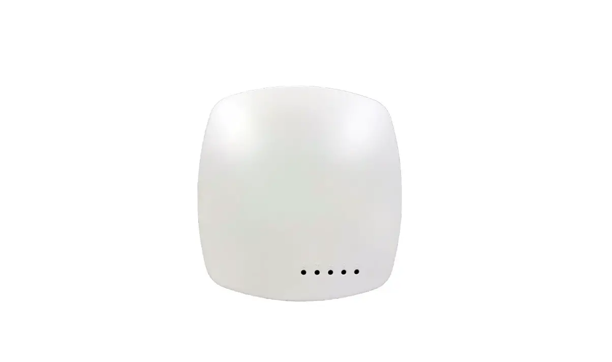
Description
GA-210 is the UWB anchor used in GIPS Real Time Location System (RTLS) solution, supports the TOF / TDOA positioning algorithm. GIPS RTLS solution can be applied in hospital, factory, warehouse and other fields.
The typical deployment structure is shown as below figure, GA-210 receives the signal from the UWB tags in the field side, and upload the packet data to the server side. GA-210 could be configured by the software on the server side, also transit the command from the server to the tags.
GA-210 supports standard IEEE802.3af PoE power supply, can be managed by PoE switch, also can powered by DC power supply. The power supply voltage is DC 5V. GA-210 supports WiFi 2.4Ghz, the data can be transferred through the wireless connection. It facilitates the deployment of the anchors in some environments.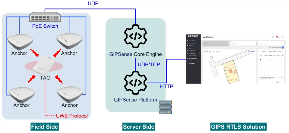
Product outline
Product Pictures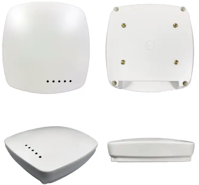
Product Dimension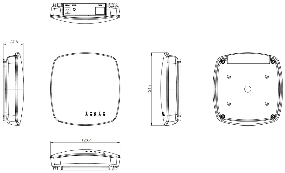
Product I/O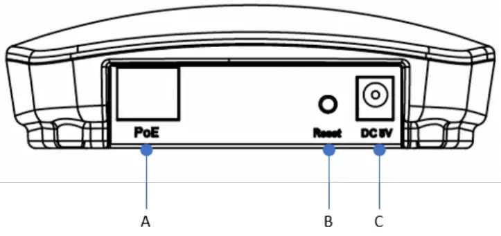
- A: RJ45, PoE supported
- B: Reset button
- C: DC-5V Input
PRODUCT SPECIFICATION
| General | |
| Standard External I/O | IEEE802.15Aa IEEE802.1 I b/g/n IEEE802.3af BLE 4.2 |
| DC power jack R345 connector Reset button | |
| Dimension (mm) Weight (g) Power Requirement | 128 x 134 x 37 |
| 250 | |
| +5V DC-in / Powered LAN(POE) | |
| Power Dissipation Indicator Light | < I.6W |
| |
| Temperature |
|
| Humidity |
|
| BLE | |
| Working Frequency Physical Rate | 3.25GHz-6.75GHz |
| 110 Kbps / 850 Kbps / 6.8 Mbps (Adjustable) | |
| Output power (25°C) | -41.3dBm/MHz – -24dBm/MHz (Adjustable) |
| Channel Bandwidth Antenna Specification | 500 MHz |
| Built-in flex antenna, peak gain 5dbi (average) | |
| Working Mode Time SYNC | ToF / TDoA |
| Wireless SYNC | |
| Wifi | |
| Protocols | IEEE 802.11 b/g/n (802.11n up to 150 Mbps) |
| Frequency Range | 2.3GHz ~ 2.5GHz |
| Antenna Specification | Built-in flex antenna, peak gain 3.2dbi (typical) |
| Modulation technique | 11b/11g/11n |
| Output power (25ºC) | Up to +21 dbm |
| Receiving sensitivity | -98 dbm |
| Channel Bandwidth | 20Mz/40MHz |
| Networking Mode | Bridge |
| WLAN Mode | AP STATION AP + STATION |
| Networking Protocol | P2P , TCP/IP , UDP , DHCP |
| Wi-Fi Encryption | AES 64/128/256 |
| Authentication | WEP / WPA-PSK / WPA2-PSK / WPS3-PSK |
| BLE | |
| Protocols | Bluetooth v4.2 BR/EDR and BLE specification |
| Radio | NZIF receiver with –97 dBm sensitivity Class-1, class-2 and class-3 transmitter AFH |
| Antenna Specification | Built-in flex antenna, peak gain 3.2dbi (typical) |
| Output power (25ºC) | +10 dbm |
| Receiving sensitivity | -98 dbm |
| Others | |
| Configuration Tools | GIPS_Anchor_Monitor_v1.0.0 (Windows Application) GIPS_BLE_Monitor_v1.0.0(Android APP) |
Federal Communication Commission Interference Statement
This equipment has been tested and found to comply with the limits for a Class B digital device, pursuant to Part 15 of the FCC Rules. These limits are designed to provide reasonable protection against harmful interference in a residential installation.
This equipment generates, uses and can radiate radio frequency energy and, if not installed and used in accordance with the instructions, may cause harmful interference to radio communications. However, there is no guarantee that interference will not occur in a particular installation. If this equipment does cause harmful interference to radio or television reception, which can be determined by turning the equipment off and on, the user is encouraged to try to correct the interference by one of the following measures:
- Reorient or relocate the receiving antenna.
- Increase the separation between the equipment and receiver.
- Connect the equipment into an outlet on a circuit different from that to which the receiver is connected.
- Consult the dealer or an experienced radio/TV technician for help.
FCC Caution: To assure continued compliance, any changes or modifications not expressly approved by the party responsible for compliance could void the user’s authority to operate this equipment. (Example – use only shielded interface cables when connecting to computer or peripheral devices).
FCC Radiation Exposure Statement
This equipment complies with FCC RF radiation exposure limits set forth for an uncontrolled environment. This equipment should be installed and operated with a minimum distance of 20 centimeters between the radiator and your body.
This transmitter must not be co-located or operating in conjunction with any other antenna or transmitter.
The antennas used for this transmitter must be installed to provide a separation distance of at least 20 cm from all persons and must not be co-located or operating in conjunction with any other antenna or transmitter.
UWB systems operating under the provisions of this section shall bear the following or similar statement in a conspicuous location on the device or in the instruction manual supplied with the device: “This equipment may only be operated indoors.
Operation outdoors is in violation of 47 U.S.C. 301 and could subject the operator to serious legal penalties.”
This device complies with Part 15 of the FCC Rules. Operation is subject to the following two conditions:
- This device may not cause harmful interference, and (2) This device must accept any interference received, including interference that may cause undesired operation.