KAIWEETS ST100 Multifunction Voltage Tester User Manual
Safety Statement
![]() Warning: Operation that may cause danger to users.
Warning: Operation that may cause danger to users.
Safety Instructions
The meter conforms to IEC61010-1 CAT.III 600V overvoltage safety standard and pollution level 2.
Safety Specification
![]() Warning
Warning
To avoid possible electric shock or personal injury, please strictly observe the following specifications:
- Operate the meter according to the manual. • Take care when measuring values exceed 60V DC, 30V AC RMS, or peak value 42V.
- If the meter is not normal or damaged, please do not use it again.
- Before using the meter, ensure that the product is intact.
- When the “
 ” symbol is displayed on the meter, replace the battery.
 - Do not use the meter in an environment with explosive gas or steam or humid environment.
- When using the probe, hold your fingers behind the probe guard.
- When measuring, please connect the null or ground wire first, then the live wire; when disconnected, please disconnect the live wire first, and then the null or ground wire.
Product Overview
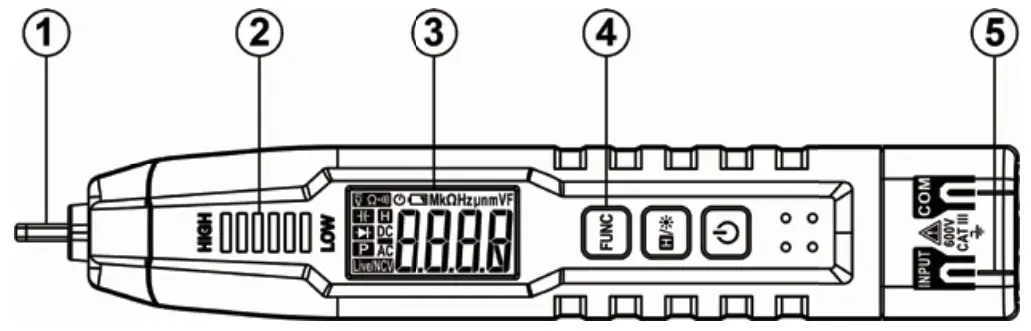
- NCV Sensor
- Signal Intensity Indicator
- LCD Display
- Function Key
- Input Jack
Power on / off
Press and hold the “![]() ” key for about 2 seconds to turn on or off.
” key for about 2 seconds to turn on or off.
Function selection
- Press “FUNC” key to select function.
- Press “FUNC” key for about 2 seconds to return to the NCV measurement.
- Power on is in NCV function mode by default.
Data hold / Flashlight
- Press “
 ” key to tum on or off data holding.
 - Press and hold “” key for about 2 seconds to turn on or off flashlight.
Auto power off
After power on, auto power off will be on by default and “![]() ” symbol will be displayed. Without any key operation in about 15 minutes, the meter will automatically shut down to save battery energy.
” symbol will be displayed. Without any key operation in about 15 minutes, the meter will automatically shut down to save battery energy.
Measurement operation
![]() Warning
Warning
- Do not measure the voltage higher than 600V, otherwise the meter may be damaged.
- Pay special attention to safety when measuring high voltage to avoid electric shock or personal injury.
- Before use, test the known voltage with the meter to confirm that the meter is in good condition.
NCV measurement
- Press the “
 ” key to power on into NCV measurement mode by default.
 - Gradually close the NCV sensing area to the measured conductor.
- When the weak electric field signal is detected, it will display “–L”; the buzzer will sound slowly and the green light on.
- When the strong electric field signal is detected, it will display “–H”; the buzzer will sound quickly and the red light on.
Smart (AUTO) measurement
In this mode, DC voltage, AC voltage, resistance, continuity can be measured, and the meter can automatically identify the measurement signal.
- Press the “” key to power on. Then press the “FUNC” key to select “AUTO” gear, the meter displays “
 ” to enter the smart testing mode.
 - Insert the red probe into “INPUT” jack and the black probe into the “COM “jack.
- Contact the probe with both ends of the measured subject or resistance in parallel, and the meter will automatically recognize the measured signal.
- When measuring the resistance, if the resistance value is < about 50 0 , the buzzer will sound.
- Read the results from the display.
Note: The minimum measurable voltage of this mode is about 0.8V.
Frequency measurement
- Press the “” key to power on, then press the ” FUNC ” key to select ” Hz ” gear.
- Insert the red probe into ” INPUT ” jack and the black probe into the “COM “jack.
- Contact the probe with both ends of the measured subject .
- Read the results from the display.
Capacitance measurement
- Press the “” key to power on, then press the “FUNC” key to select “
 ” gear.
 - Insert the red probe into ” INPUT ” jack and the black probe into the “COM “jack.
- Contact the probe with both ends of the measured capacitance .
- Read the results from the display.
Diode measurement
- Press the “” key to power on, then press the ” FUNC ” key to select “
 ” gear.
 - Insert the red probe into” INPUT” jack and the black probe into the ” COM ” jack.
- Connect the red probe to the anode of the diode and the black probe to the cathode of the diode.
- Read the forward bias value on the display screen.
Note: If the electrode of the test wire is inversely connected with the electrode of the diode, the display will read OL , which can be used to distinguish the anode and cathode of the diode.
Live wire detecting
- Press “” key to power on, then press “FUNC ” key to select “LIVE” gear.
- Insert the red probe into” INPUT ” jack and remove the black probe.
- Use the red probe contact to the conductor.
- When the weak electric field signal is detected, it will display “-12: the buzzer will sound slowly and the green light on.
- When the strong electric field signal is detected, it will display “—H “: the buzzer will sound quickly and the red light on.
Non-contact phase sequence detection
- Press “” key to power on, then press ” FUNC ” key until “PA” symbol shows on display to enter the phase sequence detection state.
- The letter “A” is flashing and stick the sensing probe to the first phase line of the socket and waiting for a beep:
- Display the “PAB” with “B” flashing and stick the sensing probe to the second phase line, wait for a beep;
- Display the “PABC” with “C” flashing and stick the sensing probe to the third phase line, wait for a long beep;
- At the end of the test, the display will show the detection results.
- “P—L” showed on the screen indicates a left-handed phase sequence.
- “P—R” showed on the screen indicates a right-handed phase sequence.
Note : Please detect the three wires within 1 minute, if not, the detection timeout error will occur, the display shows the PABC symbol and the “P” flashes at that time. Please return and test again.
General Technical Specifications
- Environment condition: CAT. III 600V: Pollution level 2, Altitude < 2000m. Working temperature and humidity: 0-40°C(<80% RH. <10°C non condensing). Storage temperature and humidity: -10-60°C(<70% RH. remove the battery). Temperature coefficient: 0.1x accuracy PC ( <18°C or >28°C )
- MAX. Voltage between terminals and earth ground: 600V.
- Sampling: approx. 3 times/second.
- Display: 4000 counts.
- Over range indication: OL”.
- Low battery indication: “Cr.
- Input polarity indication: display “—”.
- Power requirement: 2 x 1.5V AAA batteries.
Accuracy Specifications
The accuracy applies within one year after the calibration. Reference condition: the environment temperature 18°C to 28°C, the relative humidity is no more than 80%, accuracy: ±(% reading + word).
DC voltage test
Impedance: Approx.10MΩ
| Range | Resolution | Accuracy | |
| 4V | 0.001V | ±(0.5% +3) | |
| 40V | 0.01V | ||
| 400V | 0.1V | ||
| 600V | 1V | ||
| measurable voltage: 0.8V-600V | |||
AC voltage test
| Range | Resolution | Accuracy |
| 4V | 0.001V | ±(0.8%+3) |
| 40V | 0.01V | |
| 400V | 0.1V | |
| 600V | 1V | |
| measurable voltage: | 0.8V-600V | |
- Impedance: Approx.10MΩ
- Frequency Response: 4oHz-i kHz; TRMS
Resistance test
| Range | Resolution | Accuracy |
| 40000 | 10 | ±(1.0%+5) |
| 40K0 | 0.01K0 | |
| 400K0 | 0.1K0 | |
| 4M0 | 0.001 MO | |
| 40M0 | 0.01M0 | ±(1.5%+10) |
Continue test
 | <Approx. 500, Buzzer will sound and the indicator light will be on. |
Capacitance test
| Range | Resolution | Accuracy |
| 40nF | 0.01nF | ±(3.0%+5) |
| 400nF | 0.1nF | |
| 4pF | 0.001pF | |
| 40pF | 0.01pF | |
| 400pF | 0.1pF | |
| 4mF | 0.001mF |
Frequency test
| Range | Resolution | Accuracy |
| 40Hz | 0.01Hz | t(1.0%+3) |
| 400Hz | 0.1Hz | |
| 4KHz | 0.001KHz | |
| 40kHz | 0.01kHz | |
| 400kHz | 0.1kHz | |
| 4MHZ | 0.001 MHZ |
Maintenance
Clean
When cleaning the meter, please follow the following steps:
- Turn off the meter power and remove the probes.
- Wipe the case with a damp cloth or mild detergent. Do not use abrasives or solvents. Wipe the contacts in each input socket with a clean swab soaked in alcohol.
Replace battery
- Turn off the meter power and remove the probes.
- Remove the screw fixing the battery cover and remove the battery cover.
- Remove the old battery and replace it with a new one of the same specification. Please pay attention to the battery polarity.
- Install the battery cover back to its original position, and fix and lock the battery cover with screws.
3 Years Warranty
To view, print, or download the latest manual or manual supplement, visit https://kaiweets.com/pages/downloads
Go to Kaiweets YouTube channel to watch a How-to Guide and find more information about your Product.
After-sale: [email protected]

UK Authorized Representative
Company name: YH Consulting Limited
Address: C/O YH Consulting Limited Office 147, Centurion House, London Road, Staines-upon-ThamesStaines, Surrey, London, TW18 4AX
Tel: +44 07514-677868
Email: [email protected]