Flotec FP4000 Shallow Well Jet Pumps
Safety
Important Safety Instructions
SAVE THESE INSTRUCTIONS – This manual contains important instructions that should be followed during installation, operation, and maintenance of the product.
This is the safety alert symbol. When you see this symbol on your pump or in this manual, look for one of the following signal words and be alert to the potential for personal injury!
DANGER
indicates a hazard which, if not avoided, will result in death or serious injury.
WARNING
indicates a hazard which, if not avoided, could result in death or serious injury.
CAUTION
indicates a hazard which, if not avoided, could result in minor or moderate injury.
NOTICE
addresses practices not related to personal injury. Carefully read and follow all safety instructions in this manual and on pump. Keep safety labels in good condition. Replace missing or damaged safety labels. California Proposition 65 Warning
WARNING
This product and related accessories contain chemicals known to the State of California to cause cancer, birth defects or other reproductive harm.
Electrical Safety
Risk of electric shock. Can shock, burn or kill. Capacitor voltage may be hazardous. To discharge motor capacitor, hold insulated handle screwdriver BY THE HANDLE and short capacitor terminals together. Do not touch metal screwdriver blade or capacitor terminals. If in doubt, consult a qualified electrician.
General Safety
Risk of burns. Do not touch an operating motor. Motors are designed to operate at high temperatures. To avoid burns when servicing pump, allow it to cool for 20 minutes after shut-down before handling. Do not allow pump or any system component to freeze. To do so will void warranty. Pump water only with this pump. Periodically inspect pump and system components. Wear safety glasses at all times when working on pumps. Keep work area clean, uncluttered and properly lighted; store properly all unused tools and equipment. Keep visitors at a safe distance from the work areas.
CAUTION
Risk of explosion. Do not ground to a gas supply line. Pump body may explode if used as a booster pump.
WARNING
Hazardous voltage. Can shock, burn, or cause death. Ground pump before connecting to power supply. Disconnect power before working on pump, motor or tank.
- Wire motor for correct voltage. See “Electrical” section of this manual and motor nameplate.
- Ground motor before connecting to power supply.
- Meet National Electrical Code, Canadian Electrical Code, and local codes for all wiring.
- Follow wiring instructions in this manual when connecting motor to power lines.
WARNING
Hazardous pressure! Install pressure relief valve in discharge pipe. Release all pressure on system before working on any component.
Warranty
Retain Original Receipt For Warranty Eligibility
Limited Warranty
This Limited Warranty is effective June 1, 2011 and replaces all undated warranties and warranties dated before June 1, 2011. FLOTEC warrants to the original consumer purchaser (“Purchaser” or “You”) that its products are free from defects in material and workmanship for a period of twelve (12) months from the date of the original consumer purchase. If, within twelve (12) months from the original consumer purchase, any such product shall prove to be defective, it shall be repaired or replaced at FLOTEC’s option, subject to the terms and conditions set forth herein. Note that this limited warranty applies to manufacturing defects only and not to ordinary wear and tear. All mechanical devices need periodic parts and service to perform well. This limited warranty does not cover repair when normal use has exhausted the life of a part or the equipment.
The original purchase receipt and product warranty information label are required to determine warranty eligibility.
Eligibility is based on purchase date of original product – not the date of replacement under warranty. The warranty is limited to repair or replacement of original purchased product only, not replacement product (i.e. one warranty replacement allowed per purchase). Purchaser pays all removal, installation, labor, shipping, and incidental charges. For parts or troubleshooting assistance, DO NOT return product to your retail store – contact FLOTEC Customer Service at 800-365-6832. Claims made under this warranty shall be made by returning the product (except sewage pumps, see below) to the retail outlet where it was purchased or to the factory immediately after the discovery of any alleged defect. FLOTEC will subsequently take corrective action as promptly as reasonably possible. No requests for service will be accepted if received more than 30 days after the warranty expires. Warranty is not transferable and does not apply to products used in commercial/rental applications.
Sewage Pumps
DO NOT return a sewage pump (that has been installed) to your retail store. Contact FLOTEC Customer Service. Sewage pumps that have seen service and been removed carry a contamination hazard with them.
If your sewage pump has failed:
- Wear rubber gloves when handling the pump;
- For warranty purposes, return the pump’s cord tag and original receipt of purchase to the retail store;
- Dispose of the pump according to local disposal ordinances.
Exceptions to the Twelve (12) Month Limited Warranty
Product Warranty Period FP0F360AC, FP0FDC 90 days FP0S1775A, FP0S1790PCA, FP0S2400A, FP0S2450A, FP0S4100X, FP2800DCC, FPCP-20ULST, FPPSS3000, FPSC2150A, FPSC3150A, FPSC3350A 2 Years 4” Submersible Well Pumps, FP0S3200A, FP0S3250A, FP0S6000A, FPSC1725X, FPSC2200A, FPSC2250A, FPSE3601A, FPPSS5000 3 Years FP7100 Series Pressure Tanks, E100ELT, E3305TLT, E3375TLT, E5005TLTT, E50TLT, E50VLT, E75STVT, E75VLT, FPSC3200A, FPSC3250A, FPSC4550A 5 Years
General Terms and Conditions; Limitation of Remedies
You must pay all labor and shipping charges necessary to replace product covered by this warranty. This warranty does not apply to the following:
- acts of God;
- products which, in FLOTEC’s sole judgment, have been subject to negligence, abuse, accident, misapplication, tampering, or alteration;
- failures due to improper installation, operation, maintenance or storage;
- atypical or unapproved application, use or service;
- failures caused by corrosion, rust or other foreign materials in the system, or operation at pressures in excess of recommended maximums.
This warranty sets forth FLOTEC’s sole obligation and purchaser’s exclusive remedy for defective products. FLOTEC SHALL NOT BE LIABLE FOR ANY CONSEQUENTIAL, INCIDENTAL, OR CONTINGENT DAMAGES WHATSOEVER. THE FOREGOING LIMITED WARRANTIES ARE EXCLUSIVE AND IN LIEU OF ALL OTHER EXPRESS AND IMPLIED WARRANTIES, INCLUDING BUT NOT LIMITED TO IMPLIED WARRANTIES OF MERCHANTABILITY AND FITNESS FOR A PARTICULAR PURPOSE. THE FOREGOING LIMITED WARRANTIES SHALL NOT EXTEND BEYOND THE DURATION PROVIDED HEREIN. Some states do not allow the exclusion or limitation of incidental or consequential damages or limitations on how long an implied warranty lasts, so the above limitations or exclusions may not apply to You. This warranty gives You specific legal rights and You may also have other rights which vary from state to state.
Installation
Replacing An Old Pump
Risk of electric shock. Can shock, burn or kill. Disconnect power to pump before working on pump or motor.
- Drain and remove the old pump. Check the old pipe for scale, lime, rust, etc., and replace it if necessary.
- Install the pump in the system. Make sure that all pipe joints in the suction pipe are air-tight as well as water tight. If the suction pipe can suck air, the pump will not be able to pull water from the well.
- Adjust the pump mounting height so that the plumbing connections do not put a strain on the pump body. Support the pipe so that the pump body does not take the weight of piping or fittings. You have just completed the well plumbing for your new shallow well jet pump. Please go to Page 6 for discharge pipe and tank connections.
Well Point (Driven Point) Installation
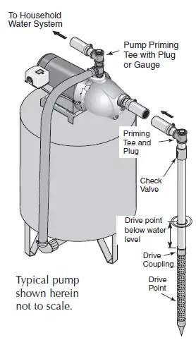
- Drive the well, using “drive couplings” and a “drive cap”. “Drive fittings” are threaded all the way through and allow the pipe ends to butt against each other so that the driving force of the maul is carried by the pipe and not by the threads. The ordinary fittings found in hardware stores are not threaded all the way through the fitting and can collapse under impact. “Drive fittings” are also smoother than standard plumbing fittings, making ground penetration easier.
2. Mount the pump as close to the well as possible.
3. Use the fewest possible fittings (especially elbows) when connecting the pipe from the well point to the pump suction port. The suction pipe should be at least as large as the suction port on the pump (include a check valve if your pump is not equipped with one – see Figure 1). Support the pipe so that there are no dips or sags in the pipe, so it doesn’t strain the pump body, and so that it slopes slightly upward from the well to the pump (high spots can cause air pockets which can air lock the pump). Seal the suction pipe joints with PTFE pipe thread sealant tape or a PTFE-based pipe joint compound. Joints must be airand water-tight. If the suction pipe can suck air, the pump cannot pull water from the well. If one well point does not supply enough water, consider connecting two or three well points to one suction pipe.
You have just completed the suction piping for your new shallow well jet pump. Please go to Page 6 for discharge pipe and tank connections.
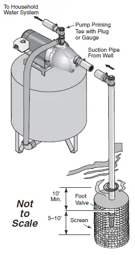
Cased Well Installation, 2” or Larger Casing
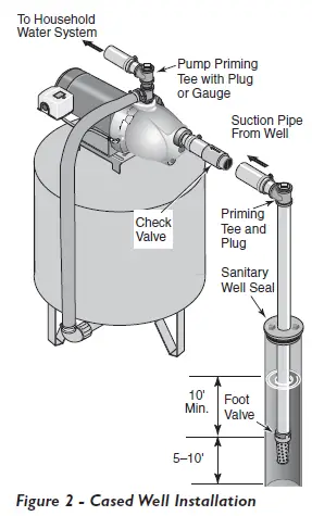
- Mount the pump as close to the well as possible.
- Assemble the foot valve, strainer, and well pipe (see Figure 2). Make sure that the foot valve works freely.
- Lower the pipe into the well until the strainer is five feet above the bottom of the well. It should also be at least 10 feet below the well’s water level while the pump is running in order to prevent the pump from sucking air. Install a sanitary well seal.
- Install a priming tee, priming plug, and suction pipe to the pump (see Figure 2). Connect the pipe from the well to the pump suction port, using the fewest possible fittings – especially elbows – as fittings increase friction in the pipe (however, include a foot valve – see Figure 2). The suction pipe should be at least as large as the suction port on the pump. Support the pipe so that there are no dips or sags in the pipe, so it doesn’t strain the pump body, and so that it slopes slightly upward from the well to the pump (high spots can cause air pockets which can air lock the pump). Seal the suction pipe joints with PTFE pipe thread sealant tape or a PTFE-based pipe joint compound. Joints must be air- and water-tight. If the suction pipe can suck air, the pump cannot pull water from the well.
Installation for Surface
Possible contamination. Do not use surface water for drinking. The installation shown could be used for sprinkler applications.
- The pump should be installed as close to the water as possible, with the fewest possible fittings (especially elbows) in the suction pipe. The suction pipe should be at least as large as the suction port on the pump.
- Assemble a foot valve and suction pipe (see Figure 3). Make sure that the foot valve works freely. Use PTFE pipe thread sealant tape or a PTFE-based pipe joint compound on threaded pipe joints. Protect the foot valve assembly from fish, trash, etc, by installing a screen around it (see Figure 3).
- Lower the pipe into the water until the strainer is five feet above the bottom. It should also be at least 10 feet below the water level in order to prevent the pump from sucking air.
- Install a priming tee, priming plug, and suction pipe to the pump (see Figure 3). Support the pipe so that there are no dips or sags in the pipe, so it doesn’t strain the pump body, and so that it slopes slightly upward from the well to the pump (high spots can cause air pockets which can air lock the pump). Seal the suction pipe joints with PTFE pipe threadsealant tape or a PTFE-based pipe joint compound. Joints must be airand water-tight. If the suction pipe can suck air, the pump cannot pull water from the water source.
You have just completed the plumbing for your new shallow well jet pump. Please go to Page 6 for discharge pipe and tank connections.
Discharge Pipe and Pressure Tank Connections
Pre-Charge Tank Connection
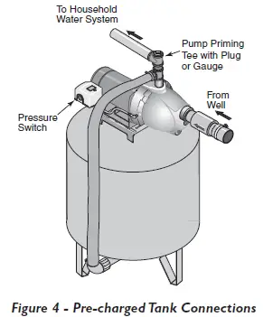
- Install two tees in the pump discharge port (see Figure 4). The pipe size must be at least as large as the discharge port.
- Run a pipe or reinforced hose from one arm of the first tee to the port on the pre-charged tank.
- Connect the other end of the discharge tee to your plumbing system. Cap the tee with a threaded plug or a pressure gauge.
- Check the pre-charge of air in the tank with an ordinary tire gauge. The pre-charge should be 2 PSI less than the cut-in setting of the pump’s pressure switch. The pre-charge is measured when there is no water pressure in the tank. Your new pump has a 30/50 PSI switch, so adjust the tank pre-charge pressure to 28 PSI.
Congratulations! You have just completed the tank connection for your jet pump. Please go to Page 7 for electrical hookup
Standard Tank Connection
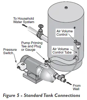
- Install one tee in the pump discharge port (see Figure 5).
- Run a pipe from the pump discharge port to the inlet port of your tank. The pipe size must be at least as large as the discharge port.
- Install a tee in the suction pipe near the pump. Install a reducer bushing down to 1/8” NPT in the tee. Run tubing from the tee to the port on the AVC mounted on the tank. Seal all joints with PTFE pipe thread sealant tape or a PTFE-based pipe joint compound. See instructions provided with the tank and the AVC for details.
Congratulations! You have just completed the tank connection for your jet pump. Please go to Page 7 for electrical hookup.
Sealing Pipe Joints
Use only PTFE pipe thread sealant tape or PTFE-based joint compounds for making all threaded connections to the pump itself. Do not use pipe joint compounds on plastic pumps: they can react with the plastic in pump components. Make sure that all pipe joints in the suction pipe are air tight as well as water tight. If the suction pipe can suck air, the pump will not be able to pull water from the well.
Electrical
WARNING
Risk of electric shock. Can shock, burn or kill. Disconnect power before working on pump, motor, pressure switch, or wiring
Motor Switch Settings
NOTICE 1/2 HP motors are dual voltage and are factory set to 115 V. 3/4 & 1 HP motors are also dual voltage, but are factory set to 230 V. Motor terminal board (located under the motor end cover) should look like that shown below. Use the instructions to set your motor to match your power source. Risk of electric shock. Can shock, burn or kill. Never connect a motor set to 115 V to a 230 V power source.
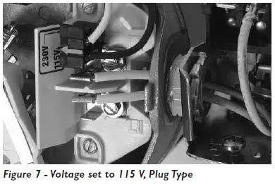
Plug Type Voltage Selector
Voltage is set to 230 V. To change to 115 V:
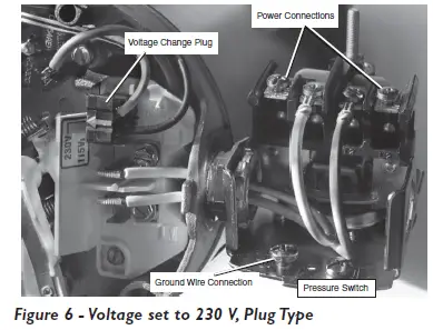
- Make sure power is off.
- Pull the voltage change plug off of the tabs.
- Move the voltage change plug to the 115 V position. The plug will now cover 2 metal tabs and the arrow on the plug will line up with the 115 V arrow on the label

- Attach the incoming power leads to the two outer screws on the pressure switch as shown in Figure 6.
- Attach the ground wire to one of the grounding connections, shown in Figure 6.
- If there are other wires, they should be capped.
- Reinstall the motor end and pressure switch covers.
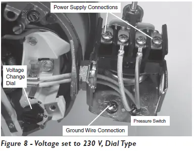
Dial Type Voltage Selector
Voltage is set to 230 volts. To change to 115 V:
- Make sure power is off.
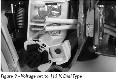
- Turn the dial counter-clockwise until 115 shows in the dial window

- Attach the incoming power leads to the two outer screws on the pressure switch as shown in Figure 8.
- Attach the ground wire to the grounding connections as shown in Figure 8.
- If there are other wires, they should be capped.
- Reinstall the motor end and pressure switch covers.

WARNING
Risk of electric shock. Can shock, burn or kill. Connect ground wire before connecting power supply wires. Use the wire size (including the ground wire) specified in the wiring chart. If possible, connect the pump to a separate branch circuit with no other appliances on it.
WARNING
Risk of explosion. Do not ground to a gas supply line.
Wiring Connections
WARNING
Risk of fire. Incorrect voltage can cause a fire or seriously damage the motor and voids the warranty. The supply voltage must be within ±10% of the motor nameplate voltage.
NOTICE
Dual-voltage motors may be set for 115 V or 230 V. If necessary, reset the motor to the desired voltage, as shown. Do not alter the wiring in single voltage motors. Install, ground, wire, and maintain your pump in compliance with the National Electrical Code (NEC) or the Canadian Electrical Code (CEC), as applicable, and with all local codes and ordinances that apply. Consult your local building inspector for code information.
Connection Procedure:
- Connect the ground wire first as shown in Figure 6. The ground wire must be a solid copper wire at least as large as the power supply wires.
- There must be a solid metal connection between the pressure switch and the motor for motor grounding protection. If the pressure switch is not connected to the motor, connect the green ground screw in the switch to the green ground screw under the motor end cover. Use a solid copper wire at least as large as the power supply wires.
- Connect the ground wire to a grounded lead in a service panel, to a metal underground water pipe, to a metal well casing at least ten feet (3 m) long, or to a ground electrode provided by the power company or the hydro authority.
- Connect the power supply wires to the pressure switch as shown in Figure 6.
You have just completed the wiring for your pump. Please go to Page 9 for startup preparations
Wiring Chart – Recommended Wire and Fuse Sizes
|
Motor HP |
Volts |
Max . Load Amp |
Branch Fuse Rating Amp | DISTANCE IN FEET FROM MOTOR TO SUPPLY | ||||
| 0 – 100 | 101 – 200 | 201 – 300 | 301 – 400 | 401 – 500 | ||||
| AWG WIRE SIZE (mm2) | ||||||||
| 1/2 | 115/230 | 9.9/4.95 | 15/15 | 14/14 (2/2) | 14/14 (2/2) | 12/14 (3/2) | 10/14 (5.5/2) | 10/12 (5.5/3) |
| 3/4 | 115/230 | 14.8/7.4 | 20/15 | 12/14 (3/2) | 8/14 (8.4/2) | 6/14 (14/2) | 6/12 (4/3) | 4/10 (21/5.5) |
| 1 | 115/230 | 19.2/9.6 | 25/15 | 10/14 (5.5/2) | 8/14 (8.4/2) | 6/12 (14/3) | 4/10 (21/5.5) | 4/10 (21/5.5) |
Preparing to Start the Pump
Priming
WARNING
Risk of explosion. Do not ground to a gas supply line. Never run pump against closed discharge. To do so can boil water inside pump, causing hazardous pressure in unit, risk of explosion and possibly scalding persons handling pump.
CAUTION
Risk of burns. Never run pump dry. Running pump without water may cause pump to overheat, damaging seal and possibly causing burns to persons handling pump. Fill pump with water before starting.
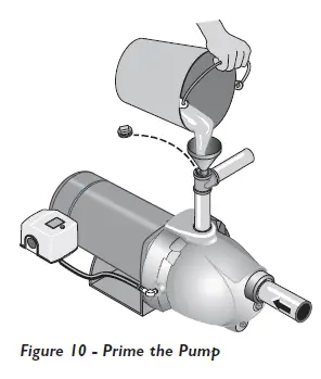
- Remove the priming plug or tee from the pump and fill the pump, fill all piping between the pump and the well, and make sure that all piping in the well is full. If you have also installed a priming tee in the suction piping, remove the plug from the tee and fill the suction piping.
- Replace all fill plugs. Open a sink faucet.
- Power on! Start the pump. If you don’t have water after 2 or 3 minutes, stop the pump and remove the fill plugs. Refill the pump and piping. You may have to repeat this several times in order to get all the trapped air out of the piping. A pump lifting water 25’ may take as long as 15 minutes to prime.
- After the pump begins building pressure in the system, shut the faucet off. Let the pump build pressure until it shuts off. Check the pressure switch operation by opening a faucet or two and running enough water out to bleed off pressure until the pump starts. The pump should start when pressure drops to 30 PSI and stop when pressure reaches 50 PSI. Run the pump through one or two complete cycles to verify correct operation. This will also help clean the system of dirt and scale dislodged during installation.
Winterizing the Pump
To prepare the pump for freezing temperatures:
- Shut off power to the pump.
- Relieve system pressure. Open a faucet and let it drain until water stops flowing.
- Drain the pump. Your pump may have a separate drain plug. Remove this plug and let it drain.
Your pump may only have a plug or connection on the side of the pump. Remove this and let the pump drain. Some water will remain in the pump. Leave the plug out until you are ready to re-prime
Troubleshooting
| Symptom | Possible Cause(s) | Corrective Action |
|
Motor will not run | Disconnect switch is off | Be sure switch is on. |
| Fuse is blown or circuit breaker tripped | Replace fuse or reset circuit breaker. | |
| Starting switch is defective | DISCONNECT POWER; Replace starting switch. | |
|
Wires at motor are loose, disconnected, or wired incorrectly | Refer to instructions on wiring (Page 9). DISCONNECT POWER; check and tighten all wiring. Risk of electric shock . Can shock, burn or kill. Capacitor voltage may be hazardous. To discharge capacitor, hold insulated handle screwdriver BY THE HANDLE and short capacitor terminals together. Do not touch metal screwdriver blade or capacitor terminals. If in doubt, consult a qualified electrician. | |
| Motor runs hot and overload kicks off | Motor is wired incorrectly | Refer to instructions on wiring. |
| Voltage is too low | Check with power company. Install heavier wiring if wire size is too small (See Electrical / Wiring Chart). | |
| Pump cycles too frequently | See section below on too frequent cycling. | |
|
Motor runs but no water is delivered*
* Stop pump; then check prime before looking for other causes. Unscrew priming plug and see if water is in priming hole. | Pump in new installation did not pick up prime through: 1. Improper priming 2. Air leaks 3. Leaking foot valve or check valve | In new installation: 1. Re-prime according to instructions. 2. Check all connections on suction line and AVC with shaving cream. 3. Replace foot valve or check valve. |
| Pump in existing installation has lost prime through: 1. Air leaks 2. Water level below suction pipe inlet | In installation already in use: 1. Check all connections on suction line and shaft seal. 2. Lower suction line into water and re-prime. If receding water level in well exceeds 25’ (7.6M), a deep well pump is needed. | |
| Foot valve or strainer is plugged | Clean foot valve or strainer. | |
| Nozzle or impeller is plugged | Clean Nozzle or impeller. | |
| Check valve or foot valve is stuck shut | Replace check valve or foot valve. | |
| Pipes are frozen | Thaw pipes. Bury pipes below frost line. Heat pit or pump house. | |
| Foot valve and/or strainer are buried in sand or mud | Raise foot valve and/or strainer above bottom of water source. Clean foot valve and strainer. | |
| Water level is too low for shallow well setup to deliver water | A deep well jet will be needed if your well is more than 25’ (7.6M) depth to water. | |
| Pump does not deliver water to full capacity (Also check point 3 immediately above) | Steel piping (if used) is corroded or limed, causing excess friction | Replace with plastic pipe where possible, otherwise with new steel pipe. |
| Piping is too small in size | Use larger piping. | |
|
Pump delivers water but does not shut off or pump cycles too frequently | Pressure switch is out of adjustment or contacts are welded together | DISCONNECT POWER; adjust or replace pressure switch. |
| Faucets have been left open | Close faucets. | |
| Venturi, nozzle or impeller is clogged | Clean venturi, nozzle or impeller. | |
| Standard pressure tank is waterlogged and has no air cushion | Drain tank to air volume control port. Check AVC for defects. Check all connections for air leaks. | |
| Pipes leak | Check connections. | |
| Foot valve leaks | Replace foot valve. | |
| Pressure switch is out of adjustment | Adjust or replace pressure switch. | |
|
Air charge too low in pre-charged tank | DISCONNECT POWER and open faucets until all pressure is relieved. Using tire pressure gauge, check air pressure in tank at valve stem located on the tank. If less than pressure switch cut-in setting (30-50 PSI), pump air into tank from outside source until air pressure is 2 PSI less than cut-in setting of switch. Check air valve for leaks (use soapy solution) and replace core if necessary. | |
|
Air spurts from faucets | Pump is picking up prime | When pump has picked up prime, it should pump solid water with no air. |
| Leak in suction side of pump | Suction pipe is sucking air. Check joints for leaks with shaving cream. | |
| Well is gaseous | Consult factory about installing a sleeve in the well. | |
| Intermittent over-pumping of well. (Water drawn down below foot valve.) | Lower foot valve if possible, otherwise restrict pump discharge. |
Repair Parts
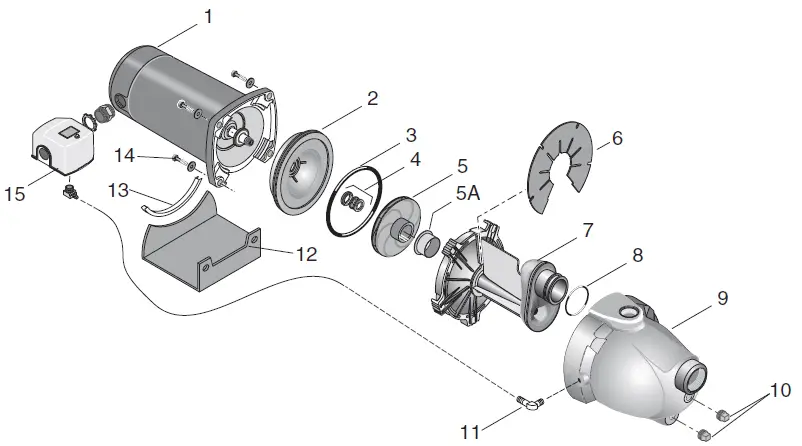
| Ref . | Description | Qty . | FP4012 | FP4022 |
| 1 | Motor | 1 | J218-582A-115-PKG | J218-590PKG |
| 2 | Seal Plate | 1 | N3-15P | |
| 3 | O-Ring | 1 | U9-390 | |
| 4 | Shaft Seal | 1 | U9-6 | |
| 5 | Impeller | 1 | J105-40PNB | J105-42PNB |
| 5A | Floating Wear Ring | 1 | N23-12SS | |
| 6 | Priming Baffle | 1 | U97-153P | |
| 7 | Nozzle / Venturi / Diffuser Assembly | 1 | N101-30PA | N101-30P |
| 8 | Nozzle O-Ring | 1 | U9-449 | |
| 9 | Pump Body | 1 | N76-46P | |
| 10 | 1/4” NPT Plug | 2 | § | |
| 11 | Barbed Fitting | 2 | U111-212T | |
| 12 | Base | 1 | J104-9F | |
| 13 | Rubber Pad | 1 | C35-5 | |
| 14 | 3/8” x 2” Capcrews | 4 | § | |
| 15 | Pressure Switch | 1 | TC2151 | |
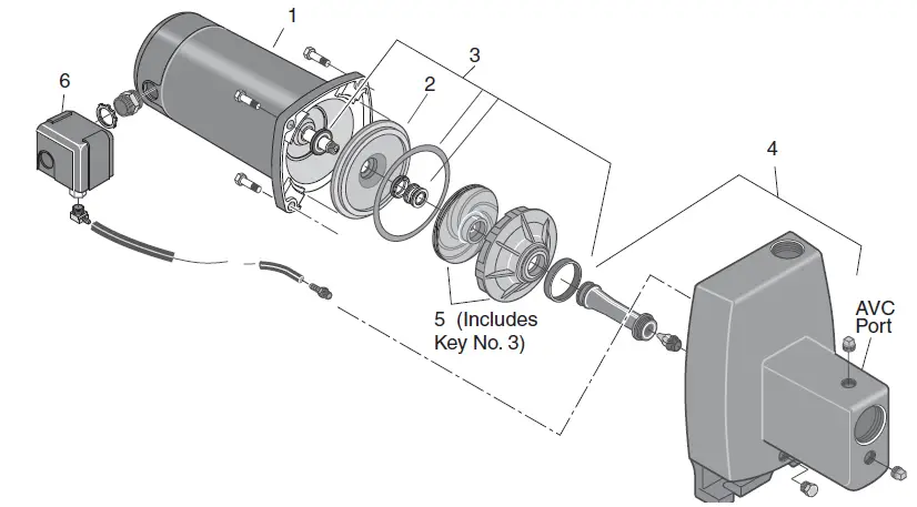
| Ref . | Part Description | FP4112 and FP4112C | FP4122 and FP4122C |
| 1 | Motor | J218-582A-115-PKG | J218-590PKG |
| 2 | Seal Plate Assembly | N3-1043P | |
| 3 | Seal and Gasket Kit** | FPP1550 | |
| 4 | Pump Body Assembly§ | N176-38 | N176-38F |
| 5 | Overhaul Kit§§ | FPP1560 | FPP1561 |
| 6 | Pressure Switch | TC2151 | |
- Includes: Water slinger, seal plate O-Ring or gasket, shaft seal, and diffuser O-Ring or gasket.
- Includes: Pump body, nozzle, and venturi.
- Includes: Seal and Gasket Kit (Ref. 3), impeller, and diffuser.
Safety
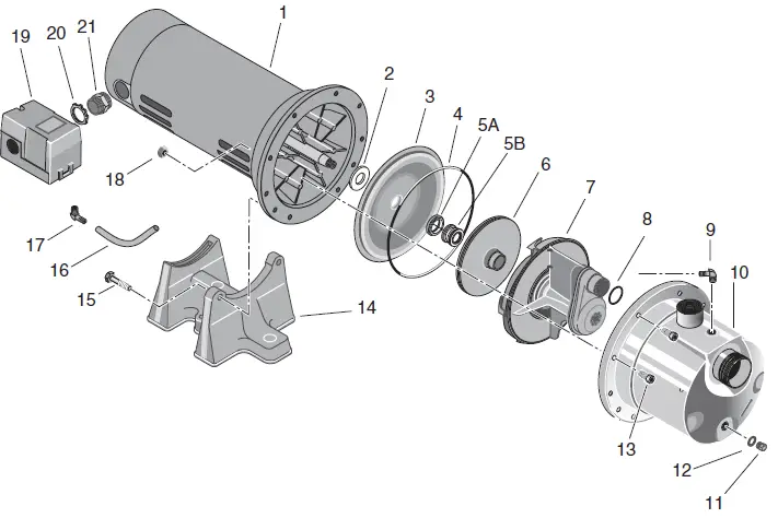
| Ref . | Part Description | Qty . | FP4822 | FP4832 |
| 1 | Motor | 1 | J218-1006 | J218-1007C |
| 2 | Slinger | 1 | C69-7 | |
| 3 | Seal Plate | 1 | 784S0070 | |
| 4 | O-Ring | 1 | 111P0490 | |
| 5A | Shaft Seal Seat | 1 | 111P0510 | |
| 5B | Shaft Seal Rotating | 1 | 111P0500 | |
| 6 | Impeller | 1 | 101P1720 | 101P1730 |
| 7 | Venturi | 1 | 101P2900 | |
| 8 | O-Ring | 1 | 111P1100 | |
| 9 | 90° Hose Barb | 1 | 171P4750T | |
| 10 | Pump Body | 1 | 723S0850 | |
| 11, 12 | Plug, Stainless Steel; Washer | 1 | 111P0990 | |
| 13 | Screw, Socket Head | 8 | 121P0310 | |
| 14 | Base | 1 | C4-42P | |
| 15 | Bolt | 2 | U30-73SS | |
| 16 | Pressure Switch Tube | 1 | U37-677P | |
| 17 | 1/4” NPT 90° Hose Barb | 1 | U111-212T | |
| 18 | Nut | 8 | U36-207SS | |
| 19 | Pressure Switch | 1 | TC2151 | |
| 20 | 1/2” Locknut | 1 | U36-112ZP | |
| 21 | Connector | 1 | L43-5C | |
For parts or assistance, call Flotec Customer Service at 800-365-6832


