![]() OWNER’S MANUAL
OWNER’S MANUAL
Shallow Well Jet Pump
2800E Shallow Well Jet Pump
293 Wright St., Delavan, WI 53115
Phone: 1-800-468-7867
1-800-546-7867
Fax: 1-800-390-5351
Installation/Operation/Parts
For further operating, installation, or maintenance assistance:
Call 1-800-468-7867
Safety
READ AND FOLLOW SAFETY INSTRUCTIONS!![]() This is the safety alert symbol. When you see this symbol on your pump or in this manual, look for one of the following signal words and be alert to the potential for personal injury.
This is the safety alert symbol. When you see this symbol on your pump or in this manual, look for one of the following signal words and be alert to the potential for personal injury.![]() DANGER warns about hazards that will cause serious personal injury, death or major property damage if ignored.
DANGER warns about hazards that will cause serious personal injury, death or major property damage if ignored.![]() WARINING warns about hazards that can cause serious
WARINING warns about hazards that can cause serious
personal injury, death or major property damage if
ignored.![]() CAUTION warns about hazards that will or can cause minor personal injury or property damage if ignored.
CAUTION warns about hazards that will or can cause minor personal injury or property damage if ignored.
The label NOTICE indicates special instructions which are important but not related to hazards.
Carefully read and follow all safety instructions in this manual and on pump.![]() WARNING
WARNING
![]() Hazardous voltage. Can shock, burn, or cause death.
Hazardous voltage. Can shock, burn, or cause death.
Ground pump before connecting to power supply. Disconnect power before working on pump, motor or tank.
Keep safety labels in good condition.
Replace missing or damaged safety labels.![]() Ground motor before connecting to power supply.
Ground motor before connecting to power supply.![]() Meet National Electrical Code, Canadian
Meet National Electrical Code, Canadian
Electrical Code, and local codes for all wiring.
ELECTRICAL SAFETY![]() WARNING Capacitor voltage may be hazardous. To discharge motor capacitor, hold insulated handle screwdriver BY THE HANDLE and short capacitor terminals together. Do not touch metal screwdriver blade or capacitor terminals. If in doubt, consult a qualified electrician.
WARNING Capacitor voltage may be hazardous. To discharge motor capacitor, hold insulated handle screwdriver BY THE HANDLE and short capacitor terminals together. Do not touch metal screwdriver blade or capacitor terminals. If in doubt, consult a qualified electrician.
GENERAL SAFETY![]() CAUTION Do not touch an operating motor. Modern motors are designed to operate at high temperatures. To avoid burns when servicing pump, allow it to cool for 20 minutes after shut-down before handling.
CAUTION Do not touch an operating motor. Modern motors are designed to operate at high temperatures. To avoid burns when servicing pump, allow it to cool for 20 minutes after shut-down before handling.
Do not allow pump or any system component to freeze.
To do so will void warranty.
Pump water only with this pump.
Periodically inspect pump and system components.
Wear safety glasses at all times when working on pumps.
Keep work area clean, uncluttered and properly lighted; store properly all unused tools and equipment.
Keep visitors at a safe distance from the work areas.![]() WARNING Pump body may explode if used as a booster pump unless relief valve capable of passing full pump flow at 75 psi is installed.
WARNING Pump body may explode if used as a booster pump unless relief valve capable of passing full pump flow at 75 psi is installed.
![]()
![]() WARNING
WARNING
Hazardous pressure!
Install pressure relief valve in discharge pipe.
Release all pressure on system before working on any component.
Simer Limited Warranty
SIMER warrants to the original consumer purchaser (“Purchaser”) of its products that they are free from defects in material or workmanship.
If within twelve (12) months from the date of the original consumer purchase any such product shall prove to be defective, it shall be repaired or replaced at SIMER’s option, subject to the terms and conditions set forth below.
Your original receipt of purchase is required to determine warranty eligibility.
Exceptions to the Twelve (12) Month Warranty
Ninety (90) Day Warranty:
If within ninety (90) days from original consumer purchase any Drill Pump or MiniVac Pump shall prove to be defective, it shall be replaced, subject to the terms set forth below.
Two (2) Year Warranty:
If within two (2) years from original consumer purchase, any 1/3 HP Submersible Sump Pump, or Models 2330, 2300 or A5500, shall prove to be defective, it shall be repaired or replaced at SIMER’s option, subject to the terms and conditions set forth below.
Three (3) Year Warranty:
If within three (3) years from original consumer purchase any 4” Submersible Well Pump, 1/2 HP Submersible Sump Pump, or Booster Pump Model 3075SS shall prove to be defective, it shall be repaired or replaced at SIMER’s option, subject to the terms and conditions set forth below.
Five (5) Year Warranty:
If within five (5) years from original consumer purchase any Pre-Charge water system tank shall prove to be defective, it shall be repaired or replaced at SIMER’s option, subject to the terms and conditions set forth below.
General Terms and Conditions
Purchaser must pay all labor and shipping charges necessary to replace product covered by this warranty. This warranty shall not apply to acts of God, nor shall it apply to products which, in the sole judgement of SIMER, have been subject to negligence, abuse, accident, misapplication, tampering, alteration; nor due to improper installation, operation, maintenance or storage; nor to other than normal application, use or service, including but not limited to, operational failures caused by corrosion, rust or other foreign materials in the system, or operation at pressures in excess of recommended maximums.
Requests for service under this warranty shall be made by returning the defective product to the Retail outlet or to SIMER as soon as possible after the discovery of any alleged defect. SIMER will subsequently take corrective action as promptly as reasonably possible. No requests for service under this warranty will be accepted if received more than 30 days after the term of the warranty.
This warranty sets forth SIMER’s sole obligation and purchaser’s exclusive remedy for defective products.
SIMER SHALL NOT BE LIABLE FOR ANY CONSEQUENTIAL, INCIDENTAL, OR CONTINGENT DAMAGES WHATSOEVER.
THE FOREGOING WARRANTIES ARE EXCLUSIVE AND IN LIEU OF ALL OTHER EXPRESS WARRANTIES. IMPLIED WARRANTIES, INCLUDING BUT NOT LIMITED TO THE IMPLIED WARRANTIES OF MERCHANTABILITY AND FITNESS FOR A PARTICULAR PURPOSE, SHALL NOT EXTEND BEYOND THE DURATION OF THE APPLICABLE EXPRESS WARRANTIES PROVIDED HEREIN.
Some states do not allow the exclusion or limitation of incidental or consequential damages or limitations on how long an implied warranty lasts, so the above limitations or exclusions may not apply to you. This warranty gives you specific legal rights and you may also have other rights which vary from state to state.
SIMER • 293 Wright Street • Delavan, WI U.S.A. 53115
Phone: 1-800-468-7867 / 1-800-546-7867
• Fax: 1-800-390-5351
E-Mail: [email protected]
• Web: http://www.simerpumps.com
Installation
SHALLOW WELL JET PUMP INSTALLATIONS:
- Have a vertical depth between the pump and the water being pumped of 25’ or less.
- Have one pipe from the well to the pump case.
- Can be installed in a bored or drilled well, or in a driven well.
REPLACING AN OLD PUMP![]() WARNING Hazardous voltage. Disconnect power to pump before working on a pump or a motor.
WARNING Hazardous voltage. Disconnect power to pump before working on a pump or a motor.
- Drain and remove the old pump. Check the old pipe for scale, lime, rust, etc., and replace it if necessary.
- Install the pump in the system. Make sure that all pipe joints in the suction pipe are air-tight as well as water tight. If the suction pipe can suck air, the pump will not be able to pull water from the well.
- Adjust the pump mounting height so that the plumbing connections do not put a strain on the pump body. Support the pipe so that the pump body does not take the weight of piping or fittings.
You have just completed the well plumbing for your new shallow well jet pump. Please go to Pages 5 and 6 for discharge pipe and tank connections.
WELL POINT (DRIVEN POINT) INSTALLATION (FIGURE 1)
- Drive the well, using drive couplings and a drive cap. Drive fittings are threaded all the way through and allow the pipe ends to butt against each other so that the driving force of the maul is carried by the pipe and not by the threads. The ordinary fittings found in hardware stores are not threaded all the way through the fitting and can collapse under impact. Drive fittings are also smoother than standard plumbing fittings, making ground penetration easier.
- Mount the pump as close to the well as possible
- Use the fewest possible fittings (especially elbows) when connecting the pipe from the well point to the pump suction port. The suction pipe should be at least as large as the suction port on the pump (include a check valve as close to the well as possible – see Figure 1). Support the pipe so that there are no dips or sags in the pipe, so it doesn’t strain the pump body, and so that it slopes slightly upward from the well to the pump (high spots can cause air pockets which can air lock the pump). Seal the suction pipe joints with teflon tape. Joints must be airand water-tight. If the suction pipe can suck air, the pump cannot pull water from the well. If one well point does not supply enough water, consider connecting two or three well points to one suction pipe.
You have just completed the suction piping for your new shallow well jet pump. Please go to Pages 5 and 6 for discharge pipe and tank connections.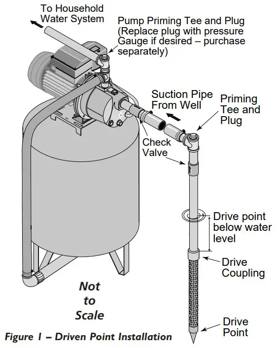
CASED WELL INSTALLATION, 2″ OR LARGER CASING (FIGURE 2)
- Mount the pump as close to the well as possible.
- Assemble the foot valve, strainer, and well pipe (see Figure 2). Make sure that the foot valve works freely.
- Lower the pipe into the well until the strainer is five feet above the bottom of the well. It should also be at least 10 feet below the well’s water level while the pump is running in order to prevent the pump from sucking air. Install a sanitary well seal.
- Install a priming tee, priming plug, and suction pipe to the pump (see Figure 2). Connect the pipe from the well to the pump suction port, using the fewest possible fittings – especially elbows – as fittings increase friction in the pipe (however, include a foot valve – see Figure 2). The suction pipe should be at least as large as the suction port on the pump. Use teflon tape on threaded pipe joints. Support the pipe so that there are no dips or sags in the pipe, so it doesn’t strain the pump body, and so that it slopes slightly upward from the well to the pump (high spots can cause air pockets which can air lock the pump). Seal the suction pipe joints with teflon tape. Joints must be air-tight and water-tight. If the suction pipe can suck air, the pump cannot pull water from the well.
You have just completed the suction piping for your new shallow well jet pump. Please go to Pages 5 and 6 for discharge pipe and tank connections.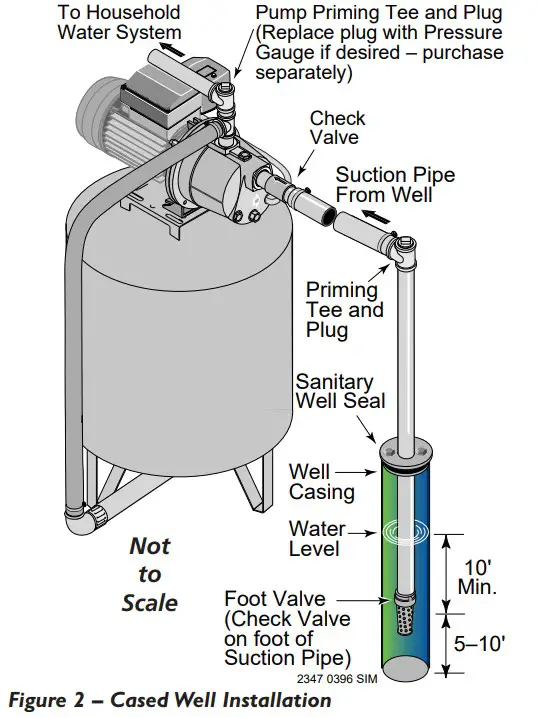
INSTALLATION FOR SURFACE WATER (FIGURE 3)
- The pump should be installed as close to the water as possible, with the fewest possible fittings (especially elbows) in the suction pipe. The suction pipe should be at least as large as the suction port on the pump.
- Assemble a foot valve and suction pipe (see Figure 3). Make sure that the foot valve works freely. Use teflon tape on threaded pipe joints. Protect the foot valve assembly from fish, trash, etc, by installing a screen around it (see Figure 3).
- Lower the pipe into the water until the strainer is five feet above the bottom. It should also be at least 10 feet below the water level in order to prevent the pump from sucking air.
- Install a priming tee, priming plug, and suction pipe to the pump (see Figure 3). Support the pipe so that there are no dips or sags in the pipe, so it doesn’t strain the pump body, and so that it slopes slightly upward from the well to the pump (high spots can cause air pockets which can air lock the pump). Seal the suction pipe joints with teflon tape. Joints must be air-tight and water-tight. If the suction pipe can suck air, the pump cannot pull water from the well.
You have just completed the plumbing for your new shallow well jet pump. Please go to Pages 5 and 6 for discharge pipe and tank connections.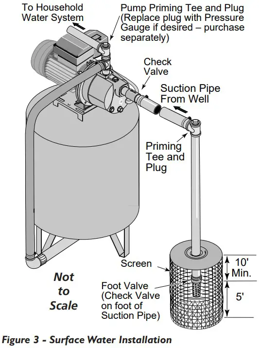
Discharge Pipe and Pressure Tank Connections
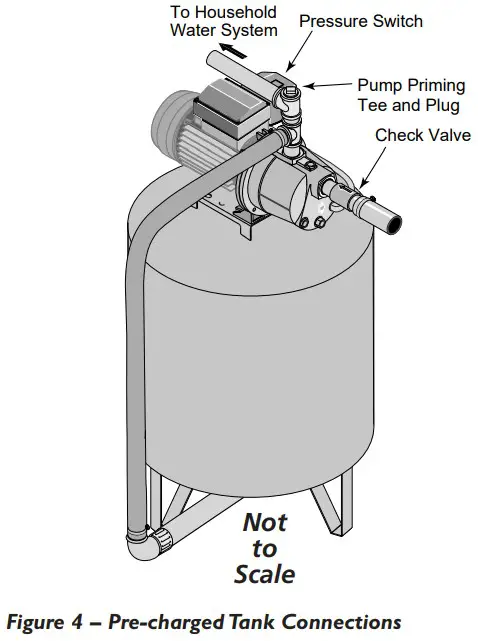
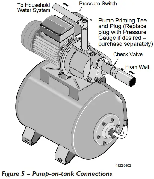
PRE-CHARGE TANK CONNECTION (FIGURES 4 AND 5)
- Install two tees in the pump discharge port (see Figure 4). The pipe size must be at least as large as the discharge port.
NOTE: A pre-plumbed pump-on-tank system only requires one tee. - Run a pipe or reinforced hose from one arm of the first tee to the port on the pre-charged tank.
- Connect the other discharge tee to your plumbing system.
- Check the pre-charge of air in the tank with an ordinary tire gauge. Your new pump has a 30/50 PSI switch, so adjust the tank pre-charge pressure to 28 PSI. The pre-charge is measured when there is no water in the tank.
The pre-charge should be 2 PSI less than the cut-in setting of the pump’s pressure switch.
Congratulations! You have just completed the tank connection for your jet pump.
 |  |
Sealing Pipe Joints
Use only teflon tape for making all threaded connections to the pump itself.
Do not use pipe joint compounds on plastic: they can react with the plastic.
Make sure that all pipe joints in the suction pipe are air tight as well as water tight. If the suction pipe can suck air, the pump will not be able to pull water from the well.
Discharge Pipe and Pressure Tank Connections / Electrical
STANDARD TANK CONNECTION (FIGURE 6)
- Install a tee in the pump discharge port (see Figure 6).
- Run a pipe from the pump discharge port to the inlet port of your tank. The pipe size must be at least as large as the discharge port.
- Install a tee with reducing bushings in the suction pipe as shown in Figure 6.
- Install a barbed fitting in the smallest bushing (1/8″ NPT).
- Run the AVC tubing from the barbed fitting on the suction pipe tee to the port in the AVC mounted on the tank. See the instructions provided with the tank and the AVC for details. The AVC port location may vary.
Congratulations! You have just completed the tank connection for your jet pump.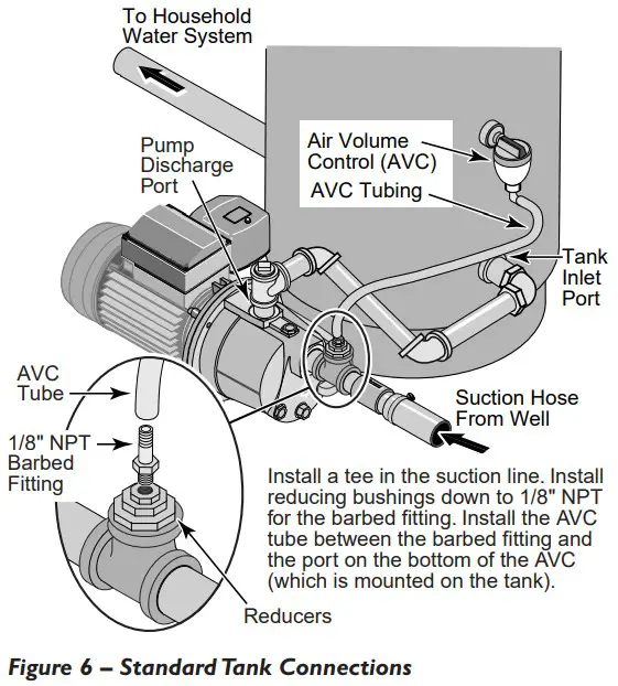
WIRING CHART – RECOMMENDED WIRE AND FUSE SIZES
Model | Volts | Maximum Load Amps | Branch Circuit Breaker Rating (Amps)* | Distance in Feet (m) from Motor To Supply Wires Sizes AWG (mm2) | |||
| 0-100 (0-30) | 101-200 (31-61) | 201-300 (62-91) | 301-400 (92-122) | ||||
| 2800, 2800E | 115 | 7.2 | 15 | 14 (2) | 12 (3) | 10 (5.5) | 8 (8.4) |
| 2802 | 115 | 8.6 | 15 | 14 (2) | 10 (5.5) | 8 (8.4) | 6 (14) |
| 2802E | 115 | 8.6 | 15 | 14 (2) | 10 (5.5) | 8 (8.4) | 6 (14) |
| 2803 | 115 | 10.5 | 15 | 14 (2) | 10 (5.5) | 10 (5.5) | 6 (14) |
* When using fuses, dual element or Fuse Tron time delay fuses are recommended for all motor circuits.
ELECTRICAL
![]() WARNING Hazardous voltage. Can shock, burn, or kill.
WARNING Hazardous voltage. Can shock, burn, or kill.
Connect ground wire before connecting power supply wires. Use the wire size (including the ground wire) specified in the wiring chart.
If possible, connect the pump to a separate branch circuit with no other appliances on it.![]() WARNING Explosion hazard. Do not ground to a gas supply line. Wiring
WARNING Explosion hazard. Do not ground to a gas supply line. Wiring![]() WARNING Fire hazard. Incorrect voltage can cause a fire or seriously damage the motor and voids the warranty.
WARNING Fire hazard. Incorrect voltage can cause a fire or seriously damage the motor and voids the warranty.
The supply voltage must be within ±10% of the motor nameplate voltage. Do not alter the wiring in the motor.
Connect to 115 Volt supply only.
Install, ground, wire, and maintain your pump in compliance with the National Electrical Code (NEC) or the Canadian Electrical Code (CEC), as applicable, and with all local codes and ordinances that apply. Consult your local building inspector for code information.
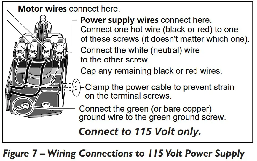
Connection Procedure:
Your Pressure Switch looks like one of those shown in Figure 7. Connect the power supply as shown for your type of switch.
- Connect the ground wire first as shown in Figure 7. The ground wire must be a solid copper wire at least as large as the power supply wires.
- There must be a solid metal connection between the pressure switch and the motor for motor grounding protection. If the pressure switch is not connected to the motor, connect the green ground screw in the switch to the green ground screw under the motor end cover. Use a solid copper wire at least as large as the power supply wires.
- Connect the ground wire to a grounded lead in a service panel, to a metal underground water pipe, to a metal well casing at least ten feet (3M) long, or to a ground electrode provided by the power company or the hydro authority.
Electrical / Preparing To Start The Pump - Connect the power supply wires to the pressure switch as shown in Figure 7.
You have just completed the wiring for your pump.
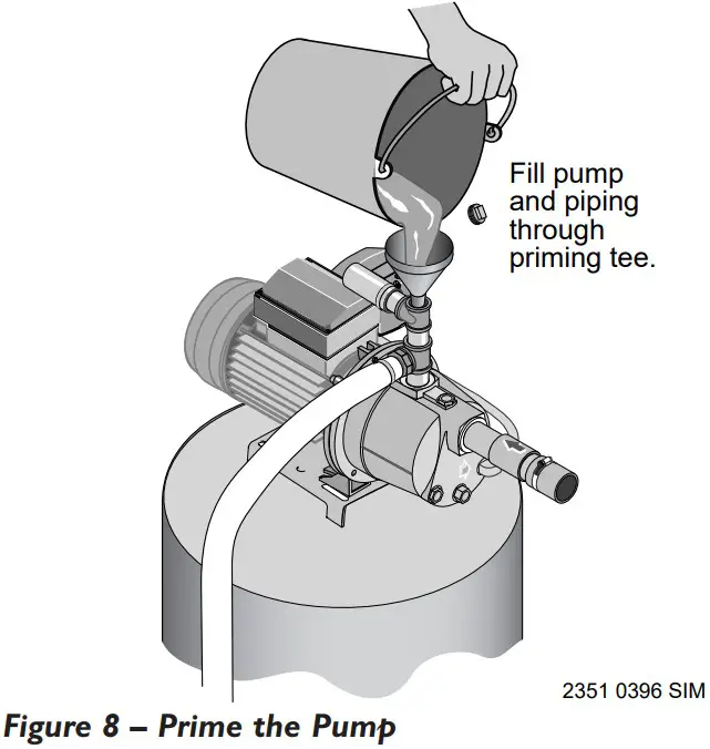
PRIMING![]() CAUTION Never run pump dry. Running pump without water may cause pump to overheat, damaging seal and possibly causing burns to persons handling pump.
CAUTION Never run pump dry. Running pump without water may cause pump to overheat, damaging seal and possibly causing burns to persons handling pump.
Fill pump with water before starting.![]() WARNING Never run pump against closed discharge.
WARNING Never run pump against closed discharge.
To do so can boil water inside pump, causing hazardous pressure in unit, risk of explosion and possibly scalding persons handling pump.
- Remove the priming plug from the priming tee and fill the pump. Fill all piping between the pump and the well and make sure that all piping in the well is full. If you have also installed a priming tee in the suction piping, remove the plug from the tee and fill the suction piping.
- Replace all fill plugs (use teflon tape).
- Power on! Start the pump. If you don’t have water in 2 minutes, stop the pump and remove the fill plugs. Refill the pump and piping. You may have to repeat this several times in order to get all the trapped air out of the piping. A pump lifting water 25’ may take as long as 15 minutes to prime.
- After the pump has built up pressure in the system and shut off, check the pressure switch operation by opening a faucet or two and running enough water out to bleed off pressure until the pump starts. The pump should start when pressure drops to 30 PSI and stop when pressure reaches 50 PSI. Run the pump through one or two complete cycles to verify correct operation. This will also help clean the system of dirt and scale dislodged during installation.
 Congratulations on a successful installation.
If you were unsuccessful, please refer to the Troubleshooting section (Page 8) or call our customer service technical staff at 1-800-468-7867.
Troubleshooting
| SYMPTOM | POSSIBLE CAUSE(S) | CORRECTIVE ACTION |
| Motor will not run | Disconnect switch is off Fuse is blown or circuit breaker tripped Wires at motor are loose, disconnected, or wired incorrectly Pressure switch contacts are dirty | Be sure switch is on. Replace fuse or reset circuit breaker. DISCONNECT POWER; check and tighten all wiring. DISCONNECT POWER and clean the electrical contacts. |
| Motor runs hot and overload kicks off | Voltage is too low Pump cycles too frequently | Check with power company. Install heavier wiring if wire size is too small. See section below on too frequent cycling. |
| Motor runs but no water is delivered • (Note: Stop pump; then check prime before looking for other causes. Unscrew priming plug and see if water is in priming hole). | Pump in new installation did not pick up prime through: 1.Improper priming 2.Air leaks 3.Leaking foot valve or check valve Pump has lost prime through: 1.Air leaks 2.Water level below suction pipe inlet Foot valve or strainer is plugged Ejector or impeller is plugged Check valve or foot valve is stuck shut Pipes are frozen Foot valve and/or strainer are buried in sand or mud Water level is too low for shallow well setup to deliver water | In new installation: 1. Re-prime according to instructions. 2. Check all connections on suction line, AVC, and ejector with shaving cream. 3. Replace foot valve or check valve. In installation already in use: 1. Check all connections on suction line and well seal. 2. Lower suction line into water and re-prime. If receding water level in well exceeds 25′ (7.6M), a deep well pump is needed. Clean foot valve or strainer. Clean ejector or impeller (See Repair Parts page). Replace check valve or foot valve. Thaw pipes. Bury pipes below frost line. Heat pit or pump house. Raise foot valve and/or strainer above bottom of water source. Clean foot valve and strainer. A deep well pump may be needed (over 25 ft. to water) to deliver water. |
| Pump does not deliver water to full capacity | Water level in well is lower than estimated Steel piping (if used) is corroded or limed, causing excess friction Piping is too small in size Packed well point | A deep well jet will be needed if your well is more than 25′ (7.6M) depth to water. Replace with plastic pipe where possible, otherwise with new steel pipe. Use larger piping. Backflush well point or sink new point. |
| Pump delivers water but does not shut off or pump cycles too frequently | Pressure switch is out of adjustment or contacts are welded together Faucets have been left open Ventura, nozzle or impeller is clogged Standard pressure tank is waterlogged and has no air cushion Pipes leak Foot valves leak Air charge too low in pre-charged tank | DISCONNECT POWER; adjust or replace pressure switch. Close faucets. Clean venture, nozzle or impeller (See Repair Parts page). Drain tank to air volume control port. Check MC for defects. Check all connections for air leaks. Check connections. Replace foot valve. DISCONNECT POWER and open faucets until all pressure is relieved. Using tire pressure gauge, check air pressure in tank at valve stem located on the tank. If necessary, adjust air pressure in tank to 28 PSI (2 PSI lower than switch cut-in setting). Check air valve for leaks (use shaving cream) and replace core if necessary. |
| Air spurts from faucets | Pump is picking up prime Leak in suction side of pump Well is gaseous Intermittent over-pumping of well. Water drawn down below foot valve.) | When pump has picked up prime, it should pump solid water with no air. Suction pipe is sucking air. Check joints for leaks with shaving cream. Consult factory about installing a sleeve in the well Lower foot valve if possible, otherwise restrict pump discharge |
Repair Parts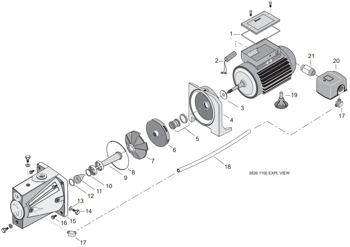
| Key No. | Part Description | No. Used | 2803 |
| 1 | O-Ring, Condenser Cover | 1 | 111P1350 |
| 2 | Condenser | 1 | 171P5750 |
| 3 | Splash Guard | 1 | 102P0540 |
| 4 | Intermediate Support | 1 | 731S1540 |
| 5 | Mechanical Seal, Stationary | 1 | ZBR00050 |
| 6 | Impeller | 1 | 101P1150 |
| 7 | Diffuser | 1 | 101P0710 |
| 8 | O-Ring | 1 | 111P0490 |
| 9 | Venturi | 1 | 101P0750 |
| 10 | O-Ring | 1 | 111P0560 |
| 11 | Nozzle | 1 | 101P0720 |
| 12 | O-Ring | 1 | 111P0480 |
| 13 | Washer | 4 | 121P0810 |
| 14 | Drain Plug | 4 | 171P1180 |
| 15 | Pump Body | 1 | 731S5600 |
| 16 | Screw, Pump Body | 4 | 121P1090 |
| 17 | 90° Hose Barb | 2 | U111-212T |
| 18 | Tubing, Pressure Switch | 1 | U37-669P |
| 19 | Motor Foot | 1 | 101P1400 |
| 20 | Pressure Switch | 1 | U217-1202 |
| 21 | Connector, 1/2″ NSPM | 1 | J43-13C |
Repair Parts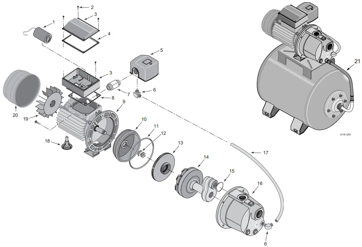
| Key No. | Part Description | No. Used | 2800 2800E | 2802 2802E |
| 1 | Capacitor | 1 | 171P5620 | 171P5430 |
| 2 | Screw 3.5 x 12.7 | 11 | 121P2060 | 121P2060 |
| 3 | 3Wiring Box and Cover | 1 | 102P2870 | 102P2870 |
| 4 | 4Wiring Box Cover Gasket | 1 | 111P1350 | 111P1350 |
| 5 | Pressure Switch | 1 | U217-1202 | U217-1202 |
| 6 | 690° Hose Barb | 2 | U111-212T | U111-212T |
| 7 | Connector, 1/2″ NSPM | 1 | J43-13C | J43-13C |
| • | Connector Lock Ring | 1 | U36-112ZP | U36-112ZP |
| 8 | 8Wiring Box Base Gasket | 1 | 111P1340 | 111P1340 |
| 9 | Seal Plate and Motor | 1 | Not Available | Separately |
| 10 | Seal Plate Insert | 1 | 101P1290 | 101P1290 |
| 11 | O-Ring | 1 | 111P0700 | 111P0700 |
| 12 | Shaft Seal, Complete | 1 | ZBR00010 | ZBR00010 |
| 13 | Impeller | 1 | 731S5700 | 731S2220 |
| 14 | Diffuser/Nozzle/Ventura | 1 | 101P3440 | 101P3440 |
| 15 | O-Ring | 1 | 111P0480 | 111P0480 |
| 16 | Volute | 1 | 731P1000 | 731P1000 |
| 17 | Pressure Switch Tube | 1 | U37-669P | U37-669P |
| 18 | Motor Foot | 1 | 101P1400 | 101P1380 |
| 19 | Fan | 1 | 102P2010 | 102P0570 |
| 20 | Motor End Cover | 1 | 201P0150 | 201P0160 |
| 21 | Flexible Pipe with Fitting (Tank to Pump, 2300E and 2802E Only) | 1 | ZA004870 | ZA004870 |
For parts or assistance, call Simer Customer
Service at 1-800-468-7867 / 1-800-546-7867


