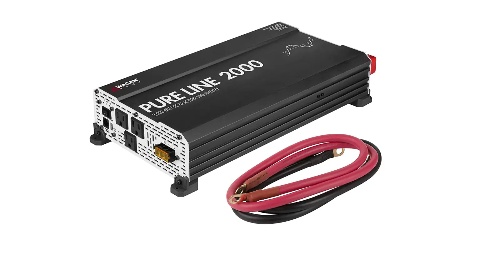

Wagan EL3808 Pure Line Power Inverter 2000
Specifications
- OUTPUT WAVEFORM: Pure sine wave
- INPUT: 12V DC
- OUTPUT: 115V AC
- TRUERATED POWER™: 2,000W (24-hour continuous)
- PEAK SURGE: 4,000 watts
- EFFICIENCY: 90%
- FREQUENCY: 60Hz
- TOTAL HARMONIC DISTORTION (THD): < 3%
- NO LOAD CURRENT DRAW: < 2.0A
- BATTERY LOW ALARM:5V ± 0.5V DC
- BATTERY LOW SHUTDOWN:0V ± 0.5V DC
- OVER VOLTAGE SHUTDOWN:5V ± 0.5V DC
- COOLING FAN: Thermally controlled
- AC OUTPUT SOCKETS: 3 North American standard
- USB POWER PORT: 2.1A, 5V
- POWER OUTPUT CONTROL: AC On/Off Switch
- DIMENSIONS: 17.5 × 8.7 × 3.7 in.
- NET WEIGHT (APPROXIMATE):7 lb
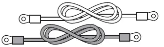
- INCLUDED DC CABLE WITH RING CONNECTORS: 36 in., 2 AWG
INTRODUCTION
Thank you for purchasing the Wagan Tech® Pure Line 2000 Pure Sine Wave DC to AC Power Inverter. Read and understand this manual before installing and operating this inverter. Keep this manual for future use.
It delivers a true AC sine wave identical to that of commercial power. Use this inverter to power AC appliances in your vehicle. Pure Sine Wave AC means that your sensitive electronics, such as audio/video systems, computers, and communications equipment will operate properly. Furthermore, appliances with motors operate cooler, quieter, and more efficiently when they are powered by pure sine wave AC.
The inverter is powered from 12 volt DC and it will continuously deliver 2,000 watts AC power at 115 volts, 60 Hz. Superior surge capability of 4,000 watts allows the inverter to start most difficult motorized appliances. Advanced microprocessor-controlled circuits run cooler and are more reliable than competing units. The Pure Line 2000 operates at high efficiency (up to 90%), that results in long run time and extended battery life compared to other inverters with this level of power output. A 2.1A USB power port provides a convenient way to power USB devices, including tablets, e-readers, smartphones, and other mobile electronics.
The Pure Line 2000 comes with a separate ground terminal typically found on higher capacity units. This terminal helps to reduce the noise caused by power conversion when using radio frequency devices.
The DC terminals have been designed with protective covers to minimize the risk of accidental shortage when handling the DC cables. This inverter bonds neutral to ground, just like utility power. The enclosure vents have been minimized to reduce the risk of pest intrusion in arid tropical climates.
This inverter has added safety features including ETL certification, conformal coating, GFCI protection, and DC terminal protection.
The Wagan Pure Line 2000 Pure Sine Wave Inverter is an indispensable addition to your compliment of mobile power equipment. With minimal care and proper treatment, it will provide years of reliable service.
WARNING
INVERTER OUTPUT CAN BE LETHAL. IMPROPER USE OF THIS INVERTER MAY RESULT IN PROPERTY DAMAGE, PERSONAL INJURY OR LOSS OF LIFE.
- Keep the inverter away from any direct heat source or combustible materials.
- Keep well ventilated—this device generates heat.
- Keep this inverter in a dry environment.
- Do not operate any equipment over 2,000 watts.
- This inverter is designed to operate from a 12 volt DC power source only.
- Do not attempt to connect the inverter to any other power source, including any AC power source.
- Incorrect battery polarity will damage the inverter and void the warranty.
- Do not open the inverter; there are no user serviceable parts inside.
DISPOSAL/RECYCLING OF INVERTER
Electronic products are known to contain materials that are toxic if improperly disposed. Contact local authorities for disposal and recycling information.
FRONT PANEL
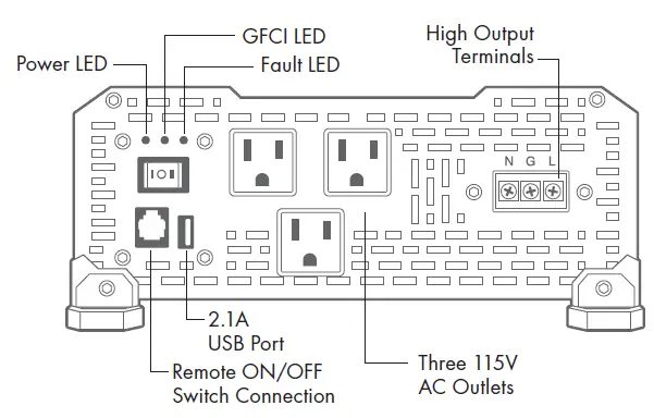
- ON/OFF Switch — This switch controls AC output of the inverter.
- Power LED (Green) — When this green LED is lit, the inverter is operating normally.
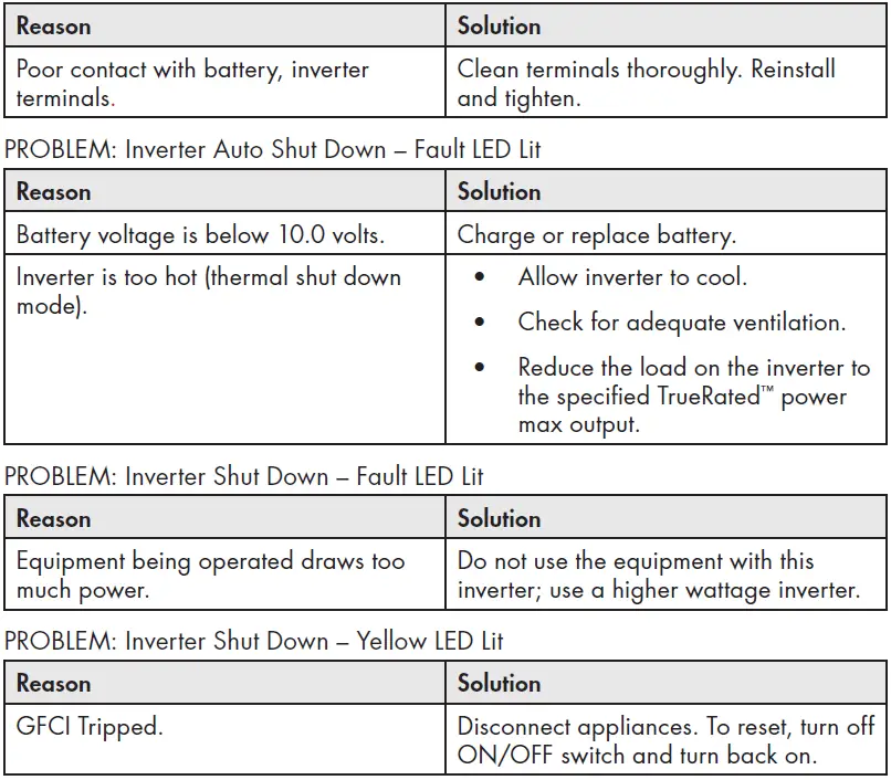
- GFCI LED (Yellow) — When the yellow LED is lit, the ground fault circuit has been interrupted. Shut down the inverter and restart.
- Fault LED (Red) — The RED indicator turns on as the inverter shuts down due to overheating, overload, under voltage, or over voltage.
- Immediately turn off all AC appliances if the FAULT LED is lit. Allow the inverter to cool before continuing. Make sure that the ventilation vents are not blocked.
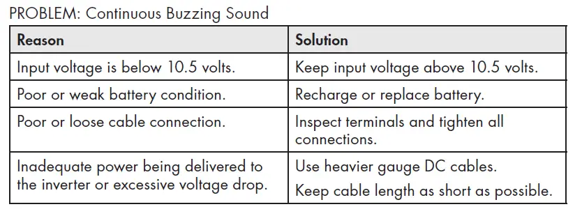
- If an inverter shutdown was preceded by a buzzing sound, there may be an excessive load in combination with a low voltage or cable problem.
- Normal operating range is 11V to 15V DC.
- AC Outlets — These outlets can supply up to 15 amps at 115V AC 60 Hz
- High Output AC Terminals — There are three insulated terminals on the front panel of the inverter. These terminals are for connecting 115 volt AC devices that require more than 15 amps to operate. Other uses are for connection to distributed wiring that has multiple AC outlets. Remove 2 screws on protective cover to access terminals. Any AC output wiring that is directly connected must comply with US National Electric Code (NEC) wiring gauge recommendations. Facing the front panel, the terminals are:


NEUTRAL and GROUND are bonded inside the inverter to comply with the National Electric Code (NEC) requirement that any AC source must have a neutral to ground connection.
- USB Power Port — This power port can supply 5 volts at 2.1A for charging or powering tablets, e-readers, smartphones, and other small electronic devices.
- Audible Alarm (internal to the inverter) — When the Audible Alarm makes a buzzing sound, the inverter senses a low battery condition. The user should reduce the AC load, charge the battery, and check the DC cable for excessive losses.
- Remote Switch Connection
REAR PANEL
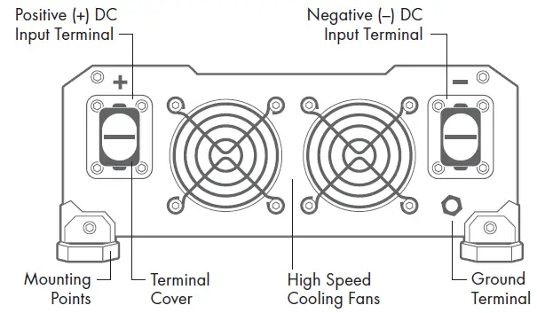
- Positive Terminal — Positive (+) DC Input (Red)
- Negative Terminal — Negative (−) DC Input (Black)
- Cooling Fans — High-speed and load controlled
- Ground Terminal — For attaching an insulated safety ground wire. This safety wire is for protecting personnel if there is an unlikely failure in either the cabling or enclosure insulation. Grounding the inverter enclosure ensures personnel safety should a DC cable problem occur. During the installation procedure, the Ground Terminal is connected either to a vehicle chassis or to the negative DC terminal of the battery. Do not directly connect this ground connection to the negative DC terminal of the inverter. Use an insulated 10 gauge wire to make the ground connection. If the inverter installation is located in fixed location, the safety wire can be connected to earth’s ground.
REMOTE ON/OFF CONTROL
- Optional wired remote control sold separately. Item #AA5603. Visit wagan.com to order.
- Insert wired remote plug into Remote Switch Connection port. Set ON/OFF switches to “remote” position.
LOAD CONSIDERATIONS
The startup load of an appliance is a major factor of whether this inverter can power it. This initial load is only momentary. With many appliances, it is approximately twice the continuous load, but some appliance startup loads can be as high as eight times the continuous load.
The inverter will automatically shut down in the event of an output overload so there is no danger of damaging either the inverter or the equipment. When the red LED indicator is lit, the inverter is signaling a fault.
PLANNING THE INVERTER SYSTEM
Any large wattage inverter system requires planning before installation. There are several steps to the planning process so the user must determine the following:
- Maximum inverter wattage required
- Operating time (run time) needed between battery recharges
- Battery bank capacity in amp-hours
- Charger requirement to charge batteries within a practical time
- Distance between battery bank and inverter
DETERMINING MAXIMUM APPLIANCE WATTAGE
Do not exceed the 2,000 watt maximum AC load or the inverter will shut down.
Most electrical tools, appliances, and audio/video equipment have labels that list the unit’s power requirements in watts. If the tool or device is rated in amps, multiply the amps by 115 (115V AC) to determine the watts. For example, an appliance rated at 0.5 amps will draw 60 watts.
WATTS = VOLTS × AMPS
Remember to consider the startup surge that motorized appliances will cause. Do not exceed the 4,000 watt momentary surge rating of this inverter. This can cause immediate overload shut down and or blow a fuse.
CONFIGURING THE BATTERY BANK
To determine the minimum battery ampere-hour rating that you will need to operate appliances from the inverter and any DC appliances powered by the battery bank, follow these steps:
- List the maximum continuous wattage that the inverter has to supply.
- Estimate the number of hours the appliances will be in use between battery recharges. This will vary depending on appliances. For example, a typical home-use coffee maker draws 500 watts during its brew time of 5 minutes. It maintains the temperature of the pot, requiring 100 watts. Typical use of a microwave oven is only for a few minutes. Some longer operating time appliances are lamps, TVs, computers, and refrigerator/freezers.
Determine the total watt-hours of energy needed. This is done by multiplying average power consumption in watts by hours of run time. For example: 500 watts for 10 hours = 5,000 watt hours. To get an estimate of the maximum current (in amps) that a battery bank must be capable of delivering to the inverter, divide the load watts by ten. For example a 500 watt appliance load will need 50 amps at 12 volts DC. Using the 500 watts (or 50 amps) for 10 hours example as above, then 50 amps is needed for 10 hours. This provides us with the basic amp-hours (AH) of battery that is required. Ten hours at 50 amps equals 500 amp-hours (AH). There are additional factors that determine actual run time. These include:
AC appliance load and time in use (basic AH).
- Cable gauge and length (cable losses).
- Charge level of the batteries (between use, chargers have to be able to fully charge the batteries).
- Temperature of the batteries (colder batteries provide fewer amps).
- Age and condition of the batteries (older batteries lose AH capacity).
- Compliance with turning off unnecessary AC loads.
- Use of DC appliances and compliance with turning off unnecessary DC loads.
DERATING THE BATTERY BANK
Most lead-acid batteries have a rating expressed in amp-hours (AH). The most common rating of AH is “at the 20 hour rate”.
NOTE: Despite several internet explanations, there is no relationship between cold cranking amps (CCA) and ampere-hours (AH).
For example, if a 20 AH battery is discharged at a 1 amp rate, is will take 20 hours to discharge that battery. The terms “charged” and “discharged” relate to actual battery voltage. This means that the output voltage of a nominal 12 volt battery starts at 13.4 volts (fully charged) then drops to 10.7 volts (discharged). If the load on the battery causes the battery to discharge faster than the 20 hour rate, the capacity (AH) of the battery is measurably reduced (derated). In heavy battery discharge applications, double the estimated Amp Hour rating and configure batteries to support this capacity. If the batteries are frequently charged by an alternator, the Amp Hour rating of the battery may be reduced.
SETTING UP THE BATTERY BANK
Batteries that are used indoors or inside a vehicle or vessel, should be deep-cycle, sealed lead acid batteries.
NOTE: It is important that for any inverter installation to battery protection fuses. Battery fuses are added to the positive (+) battery cable as close as possible to
the battery bank’s positive terminal. The fuse amperage rating must be sized to allow simultaneous operation of all the AC appliances to be powered, plus 20 percent safety factor. Fuses are very important to protect equipment, batteries, and personnel. The fuses protect against battery explosion if the cables that connect to the inverter accidentally short.
BATTERY BANK DIAGRAM
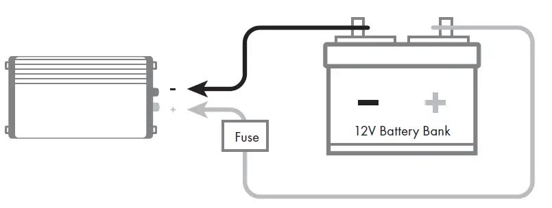
The diagram below shows inverter connections to a battery bank with recommended fuse protection.
WARNING—EXPLODING BATTERIES!!
Exploding batteries can spray molten lead, hot sulfuric acid, and other metal, and plastic fragments. Batteries that are charging or under high discharge rates produce explosive hydrogen gas into the surrounding area. Be safe–fuse the battery bank and make sure the batteries are properly ventilated.
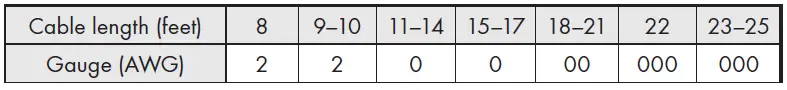
DC CABLE GAUGE
- Minimize cable losses by using the thickest wire available and the shortest practical length.
- Measure Round Trip (RT) cable distances in feet. Round Trip cable distance is battery to inverter and back to battery. If the application is in a vehicle with engine operating, use the supplied cables for round trip distances up to 5 feet.
- Use a recommended ANL fuse and Fuse holder. Fuse at 250 Amps. ANL fuses are quick acting and sealed so they do not spark when they blow. Place fuse no more than one foot from the Positive (+) terminal of the battery.

CONNECTING THE INVERTER
Installation procedure:
- Mount the inverter in a secure location. If the inverter is to be mounted on a wall, mount it horizontally. Make sure that the front and rear of the inverter has free air flow.
- Make sure the cables are the proper gauge and have the fuse holder as close to the battery bank’s Positive (red) terminal.
- Install the fuse in the Positive (red) cable.
- Make sure the Power Switch located on the front panel of the inverter is in the Off position.
- Locate the ground lug terminal on the inverter. Connect an insulated 10 gauge copper wire to the terminal. The other end of the ground wire is connected to a “proper” grounding point. Use the shortest practical length of wire. Connect this wire to the chassis of your vehicle or to the grounding system in your boat. In a city, the ground wire can connect to a metal cold water pipe that goes underground. In remote locations, the ground wire can be connected to an “earth ground”. This can be an attachment to a foot long copper clad metal rod driven into the ground. In the unlikely event of a short circuit, operating the inverter without proper grounding can result in electrical shock. Do not directly connect this ground wire to the Negative (black) DC Terminal of the inverter. As an alternative grounding connection, use the Negative (black) terminal of the battery.
NOTE: Crimp-on ring terminals are required on all cable ends. The cable ends need to be stripped of insulation for 1/2 inch before crimping on ring terminals. Select a crimp terminal size to fit the gauge cable and inverter and battery terminal connectors. After crimping make sure that the cable connectors are secure on the cables so there are no loose connections.
- Remove the terminal covers from the inverter. Slide the cable through the correct terminal cover.
- Connect the Negative (black) cable end to the inverter terminal and battery Negative Terminal. Make sure you have good, secure connections.
- Recheck and make sure the DC cable fuse is installed in the fuse holder. CAUTION: Making an initial connection between the positive cable end and the inverter’s positive terminal may cause a spark. This is a normal and is a result of capacitors in the inverter starting to charge. Because of the possibility of sparking, it is extremely important that both the inverter and the battery bank be positioned away from any source of flammable fumes or gases. Failure to heed this warning can result in fire or explosion. Do not make the positive terminal connection immediately after the batteries have been charging. Allow time for the battery gasses to vent to outside air.
- Attach the positive cable to the Positive DC connector on the battery and then the inverter. Make sure the connections are tight and secure.
- Turn on the inverter from the Front Panel Power Switch “|” Make certain that the green Operating LED is lit and the FAULT LED indicator is not lit.
- Turn Off “O” the inverter. The Fault LED may briefly “flash”. This is normal. The audible alarm may also sound a short “chirp”. This is also normal.
- When you have confirmed that the appliance to be operated is turned off, plug the appliance into one of the two AC outlets on the front panel of the inverter.
- Turn the inverter on.
- Turn the appliance on. The appliance should begin working.
- Observe the LED indicators and the digital display for normal operation.
Note: If an extension cord is used from the inverter to the appliance, limit the extension cord length to 100 feet or less. Make sure that the cord is safety approved and AWG 14 or greater to carry the appliance load. Remember that extension cords are for temporary use.
WARNING: THERE IS DANGER OF EXPLOSION. DO NOT CONNECT OR DISCONNECT CHARGER CABLES DIRECTLY AFTER BATTERY DISCHARGE OR RECHARGE—MAKE SURE THAT THE BATTERY BANK AREA IS WELL VENTED BEFORE ATTACHING OR REMOVING CABLES.
OPERATING ISSUES: TELEVISION AND AUDIO
EQUIPMENT SUGGESTIONS.
Although all inverters are shielded and filtered to minimize signal interference, some interference with your television picture may be unavoidable, especially with weak signals. However, here are some suggestions that may improve reception.
- Make sure that the television antenna produces a clear signal under normal operating conditions (i.e. plugged into a standard 110V/115V AC wall outlet). Also ensure that the antenna cable is of good quality and properly shielded.
- Sometimes vehicle alternators produce some electrical noise. There are filters available to mount on the alternator to reduce the noise.
- Change the positions of the inverter, antenna cables, and television power cord.
- Isolate the television, its power cord, and antenna cables from the 12 volt power source by running an extension cord from the inverter to the television.
TROUBLESHOOTING
WAGAN Corp. Limited Warranty
The WAGAN Corporation warranty is limited to products sold only in the United States.
Warranty Duration
Product is warranted to the original purchaser for a period of two (2) years from the original purchase date, to be free of defects in material and workmanship. WAGAN Corporation disclaims any liability for consequential damages. In no event will WAGAN Corporation be responsible for any amount of damages beyond the amount paid for the product at retail.
Warranty Performance
During the warranty period, a product with a defect will be replaced with a comparable model when the product is returned to WAGAN Corporation with an original store receipt. WAGAN Corporation will, at its discretion, replace or repair the defective part. The replacement product will be warranted for the balance of the original warranty period. This warranty does not extend to any units which have been used in violation of written instructions furnished.
Warranty Disclaimers
This warranty is in lieu of all warranties expressed or implied and no representative or person is authorized to assume any other liability in connection with the sale of our products. There shall be no claims for defects or failure of performance or product failure under any theory of tort, contract or commercial law including,but not limited to negligence, gross negligence, strict liability, breach of warranty, and breach of contract.
Returns
WAGAN Corporation is not responsible for any item(s) returned without an official Return Authorization number (RA#). Please contact our customer service team by phone or email to obtain an RA#. You can also visit our website and chat with our team during our normal business hours. For more details and instructions on how to process a warranty claim, please read the “Returns” section under the “Contact” page on our website. WAGAN Corporation is not responsible for any shipping charges incurred in returning the item(s) back to the company for repair or replacement.
Register your product online at http://tinyurl.com/wagan-registration to be added to our email list. You will receive previews on our upcoming products, promotions, and events.
FAQs
A 2000W inverter has enough power to run any single appliance, from deep freezers to microwaves. A 2000W inverter may not be enough to power a complete home, but it will undoubtedly be adequate for any travel or off-grid uses.
Two things that pure sine wave inverters excel at are effectively powering AC-powered devices and effectively powering interference-prone equipment like radios. However, they can be pricey.
An electronic device known as a pure sine wave inverter transforms direct current (DC) into alternating current (AC). By transforming the DC input into a pure sine wave output, it achieves this.
The AC power generated by pure sine wave inverters closely resembles a real sine wave. Modified sine wave inverters have a sudden positive to negative polarity change. The wave appears to have a stair-step, square pattern when viewed from above, with the polarity alternately flipped.
For a 2,000 watt inverter like the one you mentioned with part number 34278156, two batteries are typically required.
The solar industry as a whole is aware that string inverters may normally survive between 10 and 15 years, and even up to 20 years in some exceptional circumstances, with regular maintenance checks.
A 1500 watt inverter can be run continuously for 13 minutes on a 12 volt 50 Ah lithium iron phosphate (LiFP04) battery with a regular depth of discharge (DoD) of 80%. The calculation takes into account the normal 95% efficiency of pure sine wave inverters.
A modified sine wave inverter will serve your needs if you want to use it mostly to power appliances like lights, TVs, microwaves, and tools.
A delicate electrical appliance is a refrigerator. So, for refrigerators, a constant supply of high-efficiency voltage is necessary. A pure sine wave refrigerator is your best choice if you want to safeguard the fridge from internal circuit damage.
While using customized sine wave inverters with your electronics is not strictly wrong, there are significant risks involved. In fact, some sorts of electrical gadgets may be damaged by these sine wave inverters. This is more of an exception than a rule, you could say.
By adding up the most watts you’ll ever use at once and adding 20%, you can quickly determine the size of inverter you’ll need. Let’s imagine, for illustration purposes, that you require 1,500 watts to simultaneously power your computer and microwave. Consider 1,500 Plus 300 (20% of 1,500), which is 1,800 watts.
Seven 300 watt solar panels are strongly advised for a 2000 watt solar inverter. This is due to the fact that 7 300 watt solar panels for a 2000 watt inverter take up less space than a 200 watt or 100 watt inverter.


