![]()
Drive OTR Antenna Installation Guide
Model: 311229
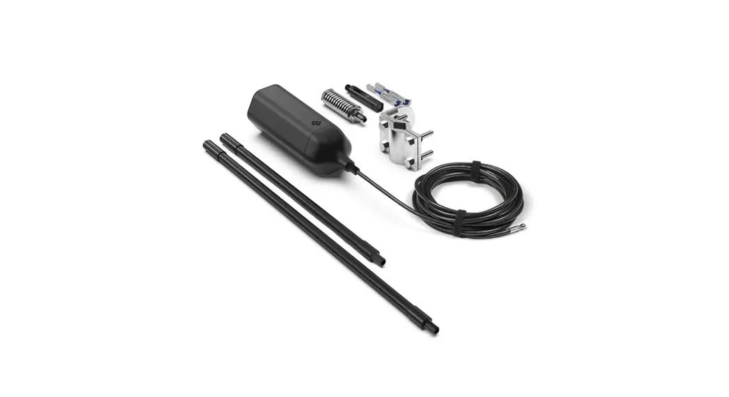
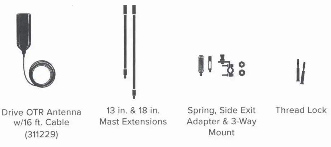
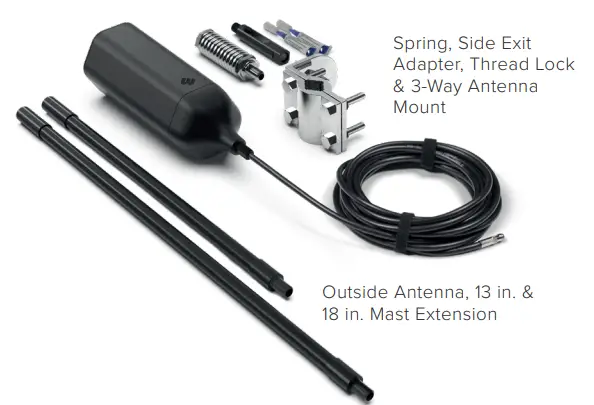
Package Contents
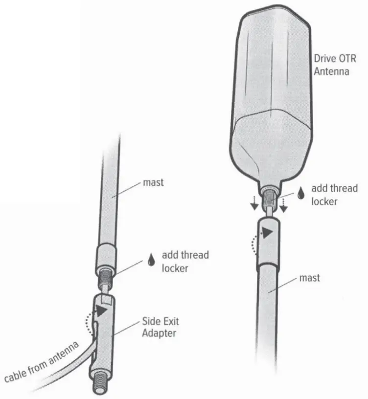
Select Mounting Location & Assemble the Antenna
Once you have determined the best location for the antenna, insert cable through the mast(s) and then through Side Exit Adapter.
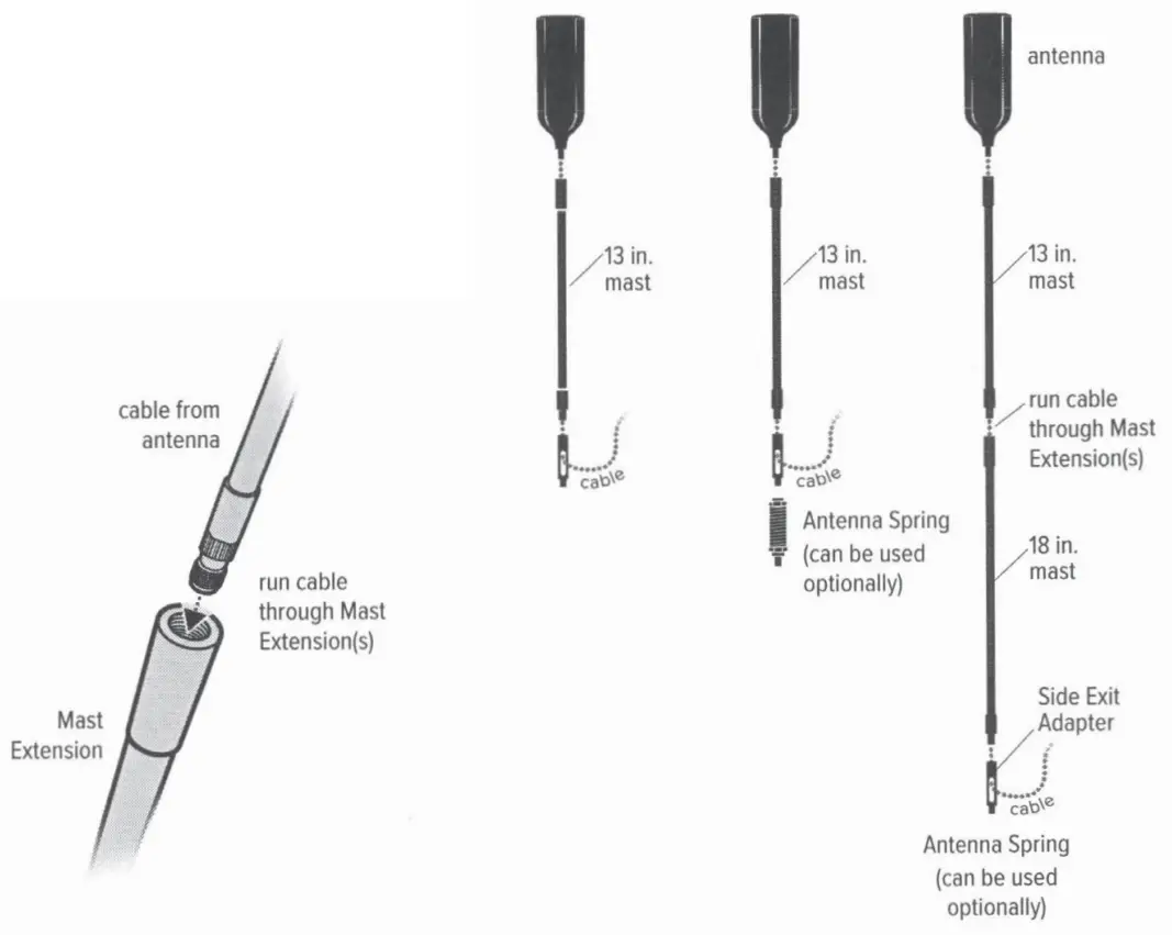
Use the thread locker (provided) to thread points and screw them into place.
NOTE: Be sure the antenna is at the correct height before applying the thread locker.
NOTE: When adding the side exit adapter holds the antenna vertically and screw the adapter from the bottom up. This reduces cable twisting.
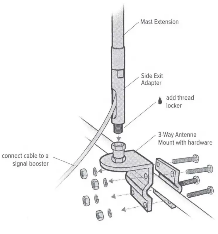
Mounting the Antenna
lf the vehicle does not have built-in Mast Extension mounting points, a three-way mount is included that will work on vehicles with mirror rails.
NOTE: The cable is strong enough that it may be shut in most vehicle doors without damaging the cable.
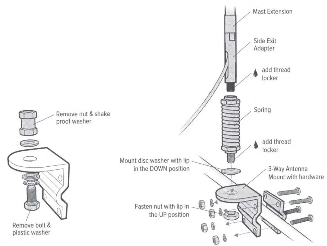
Mounting the Antenna with Spring
If installing with the Spring, disassemble the 3-Way Mount and use the disc washer and nut (provided) to mount the antenna with Spring as shown.
Safety Guidelines & Specifications
RF Safety Warning: Any antenna used with this device must be located at least 8 inches from all persons. AWS Warning: The Outside Antenna must be installed no higher than 32 feet 9 inches (10 meters) above ground.
| Electrical Specifications | ||||||
| Frequency Band (MHz) | 698-806 | 806-960 | 1710-1880 | 1850-1990 | 1910-2170 | 2300-2700 |
| Peak Gain (dBi) | 2.4 | 2.6 | 3.8 | 3.8 | 3.7 | 4.3 |
| Gain (dBi), Typical @ 2° Elevation | 1.4 | 2.4 | 3.1 | 2.7 | 2.4 | 2.6 |
| Cable loss LMR-195 30 in. | 1.8 | 1.9 | 2.8 | 2.9 | 3.0 | 3.3 |
| VSWR | <2:1 | <2:1 | ||||
| Efficiency (%) | >70 | >65 | ||||
| Polarization | Vertical | |||||
| Half-Power Azimuth Beamwidth (0) | 360 | 360 | 360 | 360 | 360 | 360 |
| Half-Power Elevation Beamwidth (0) | 70 | 78 | 60 | 70 | 80 | 33 |
| Impedance (Ω) | 50 | |||||
| Maximum Power (W) | 10 | |||||
Mechanical Specifications
| Model | 311229, .. |
| Connector | SMA(F) |
| Dimensions (in / mm) | 7.422 X 2.688 / 188 X 68 |
| Weight (lb / kg) | JS/ .340 |
| Rated Wind Velocity (mph/kph) | 311 / 500 |
| Radiator Material | Aluminum |
| Radome Material | Alumni Plas~c Type: ASA (Acrylonitrile Styrene) Acrylate) |
2 YEAR WARRANTY
Antennas may also be returned directly to the manufacturer at the consumer’s expense, with a dated proof of purchase and a Returned Material Authorization (RMA) number supplied by Wilson Electronics. Wilson Electronics shall, at its option, either repair or replace the product. Wilson Electronics will pay for the delivery of the repaired or replaced product back to the original consumer if located within the continental U.S. Replacement products may include refurbished Wilson Electronics products that have been recertified to conform with product specifications.
This warranty does not apply to any antennas determined by Wilson Electronics to have been subjected to misuse, abuse, neglect, or mishandling that alters or damages physical or electronic properties. RMA numbers may be obtained by contacting Technical Support at 866-294-1660.
DISCLAIMER: The information provided by Wilson Electronics, LLC is believed to be complete and accurate. However, no responsibility is assumed by Wilson Electronics, LLC for any business or personal losses arising from its use, or for any infringements of patents or other rights of third parties that may result from its use.
MARKETING APPROVAL: Installer and end customer hereby grant to Wilson Electronics the express right to use the installer or end customer’s company logo in marketing, sales, financial, and public relations materials and other communications solely to identify the Customer as a Wilson Electronics customer.
![]()
3301 East Deseret Drive, St. George, UT
![]()
![]() 866.294.1660
866.294.1660![]() www.wilsonelectronics.com
www.wilsonelectronics.com![]() [email protected]
[email protected]
Copyright © 2020 Wilson Electronics. All rights reserved. Wilson Electronics products covered by U.S. patent(s) and pending
application(s) For patents go to: weboost.com/us/patents
NOT AFFILIATED WITH WILSON ANTENNA
GDE000299_Rev02_02.24.21
Drive OTR Antenna
SKU: 311229
MAP: $99.99
FEATURES
- Covers 700, 800, 1700, 1900, 2200 MHz cellular
- All modes, voice and data
- High gain signal output
- The antenna can be configured into multiple lengths from 7.5-40 in.
- Off-road rated to MIL-STD 810H for shock and vibration
- Works with standard CB antenna mounts, includes3-way mirror rail mount
- Connects to mobile cellular boosters
- IP66 rated for outdoor use
- Assembled in the USA
- 2 year warranty
Kit Includes
![]() WARNING: This product can expose you to chemicals including Nickel, which is known to the State of California to cause cancer, and Bisphenol A, which is known to the State of California to cause birth defects or other reproductive harm. For more information go to www.P65Warnings.ca.gov
WARNING: This product can expose you to chemicals including Nickel, which is known to the State of California to cause cancer, and Bisphenol A, which is known to the State of California to cause birth defects or other reproductive harm. For more information go to www.P65Warnings.ca.gov
Specifications
| ELECTRICAL | ||||||
| Frequency Band (MHz) | 698-806 | 806-960 | 1710-1880 | 1850-1990 | 1910-2170 | 2300-2700 |
| Peak Gain (dBi) | 2.4 | 2.6 | 3.8 | 3.8 | 3.7 | 4.3 |
| Gain (dBi), Typical @ 2° Elevation | 1.4 | 2.4 | 3.1 | 2.7 | 2.4 | 2.6 |
| Cable loss LMR-195 30 in. | 1.8 | 1.9 | 2.8 | 2.9 | 3.0 | 3.3 |
| Efficiency (%) | >70 % | >65% | ||||
| VSWR | <2:1 | <2:1 | ||||
| Polarization | Vertical | |||||
| Half-Power Azimuth Beamwidth (0) | 360 | 360 | 360 | 360 | 360 | 360 |
| Half-Power Elevation Beamwidth (0) | 70 | 78 | 60 | 70 | 80 | 33 |
| Impedance (Ω) | 50 | |||||
| Maximum Power (W) | 10 | |||||
MECHANICAL
| Model | 311230 |
| Connector | SMA Male / SMB Plug |
| Feed Cable Length (in / mm) | 30 / 762 |
| Dimensions (in / mm) | 7.422×2.688 / 188×68 |
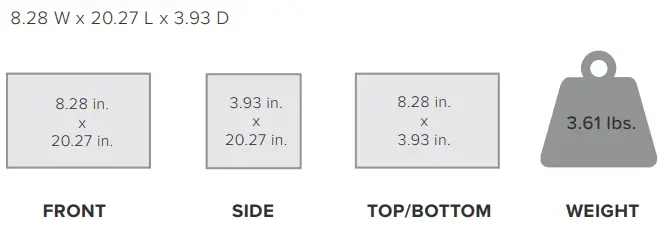
| Packaged Dimensions (in / mm | 8.28×20.27×3.93 / 210x515x100 |
| Packaged Weight (lb / kg) | 3.61 / 1.6 |
| Wind Loading Area (ft2/m2) | .246 ft^2 / .0229m^2 |
| Rated Wind Velocity (mph/kph) | 311 mph / 500km/h |
| Radiator Material | Aluminum |
| Radome Material | Alumni Plastic Type: ASA (Acrylonitrile Styrene Acrylate) |
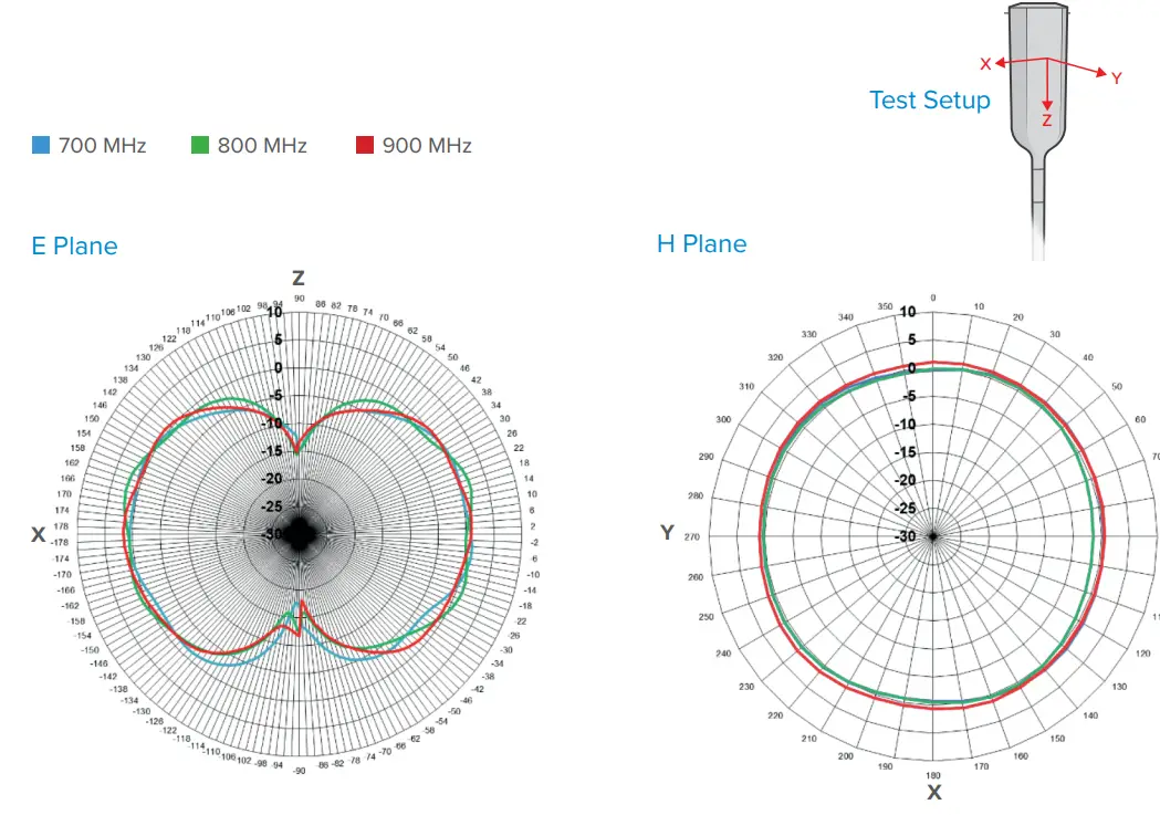
Radiation Patterns, 700-900 MHz
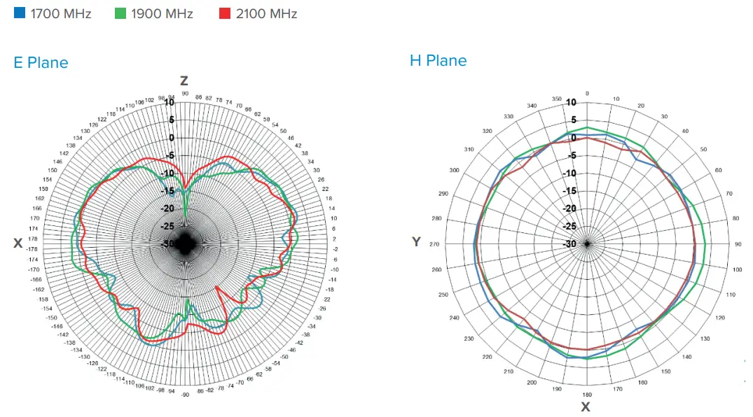
Radiation Patterns, 1700-2100 MHz
Radiation Patterns, 2300-2700 MHz
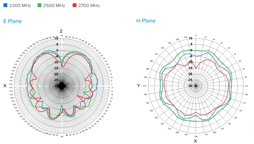
Note: Gain values at 2° elevation indicated are without cable loss. Please refer to the electrical specs chart to include cable losses.
Peak Gain (@ 2° Elevation)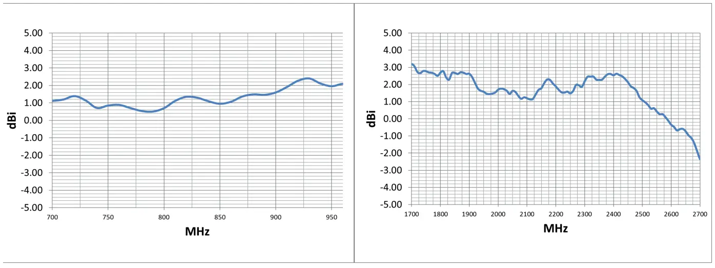 Efficiency (%)
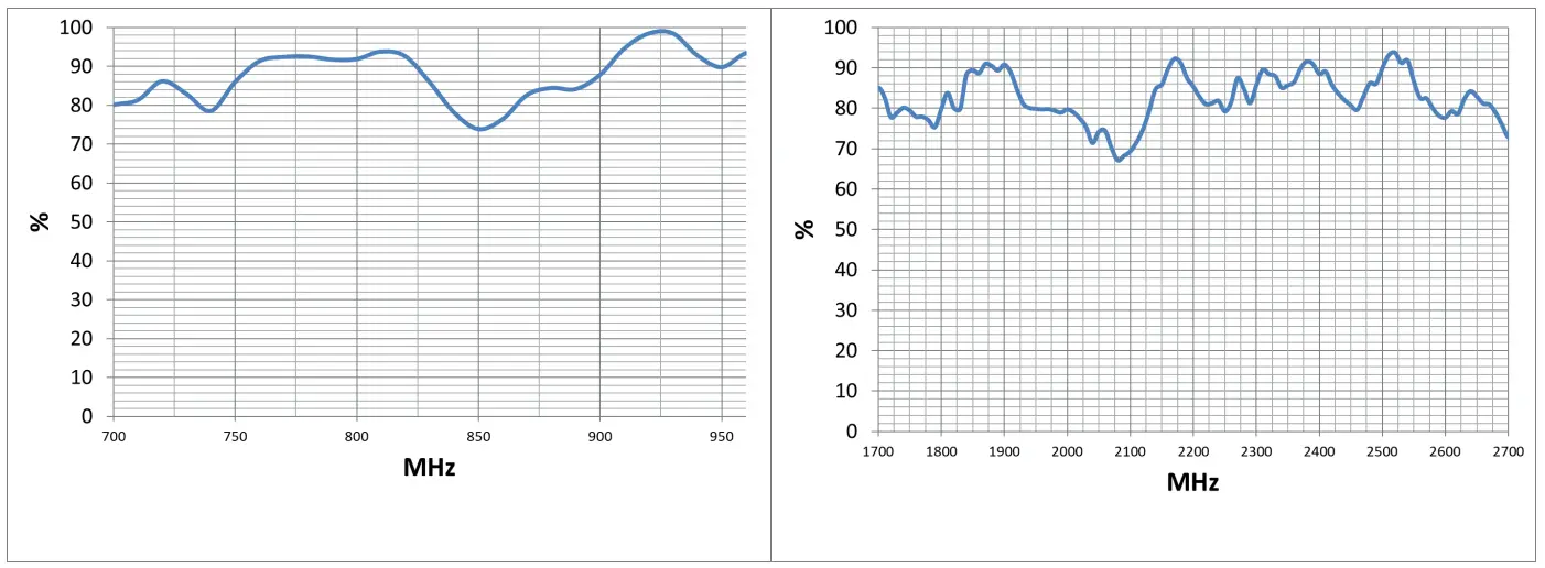 Note: Gain values at 2° elevation indicated are without cable loss. Please refer to the electrical specs chart to include cable losses.
Package Dimensions
FOR PARTNER’S USE
Support
2 Year Warranty
Email: [email protected]
Website: http://support.weboost.com
Phone: +1 866 294 1660 Monday to Saturday![]() WARNING: Cancer and Reproductive Harm – www.P65Warnings.ca.gov.
WARNING: Cancer and Reproductive Harm – www.P65Warnings.ca.gov.![]() ASSEMBLED IN THE USA
ASSEMBLED IN THE USA

•••
Need help?
Contact us directly.![]() support.weboost.com
support.weboost.com ![]() 866.294.1660
866.294.1660![]() SIGNAL BARS CAN BE INACCURATE
SIGNAL BARS CAN BE INACCURATE
Signal boost is best measured in how much better you can communicate than before’
To learn more please visit: weboost.com/signalbars


