![]() Electric Storage Water Heater
Electric Storage Water Heater
USER MANUAL
AST-30-H/AST-40-H/AST-50-H/
AST-60-H/AST-70-H/AST-80-H/
AST-90-H
SAFETY PRECAUTION
- Installation and maintenance work shall only be performed by a qualified person, familiar with local code and regulation, and experienced with this type of appliance.
- All field wiring must be installed in accordance with the national wiring regulation.
- This appliance is not intended for use by persons (including children) with reduced physical, sensory or mental capabilities, or lack of experience and knowledge, unless they have been given supervision or instruction concerning use of the appliance by a person responsible for their safety.
- Children should be supervised to ensure that they do not play with the appliances.
- Do not attempt to repair the appliance yourself.
- The electrical water heater must be installed with a mono-directional Pressure Relief Valve at the inlet pipe. The pressure relief device is to be operated regularly to remove lime deposit and to verify that there is no blockage.
- The water may drip from the Discharge Pipe of the pressure relief device and that this pipe must be left open to surrounding air. A Discharge Pipe connected to the pressure-relief device is to be installed in a downward direction and in a frost-free environment.
- The electrical water heater must be prefitted with isolation barriers at both inlet and outlet connections.
- The heater must be permanently connected to the electricity supply through a double-pole-linked switch with a contact separation of at least 3mm in all poles incorporated in the circuit.
- If the supply cord is damaged, it must be replaced by the manufacturer, service agent or a similarly qualified personnel in order to avoid hazards.
- In order to avoid hazards due to inadvertent resetting of the thermal cut-out, this appliance can not be supplied through an external switching device, such as a timer, or connected to a circuit that is regularly switched on and off by the utility.
PARTS IDENTIFICATION
External Part Identification
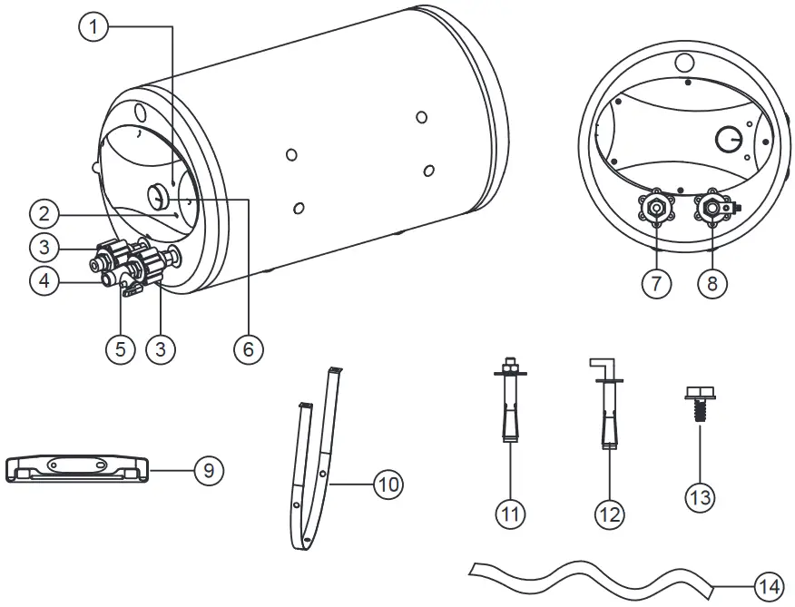
| 1. Power Indicator 2. Heating Indicator 3. Isolation Barrier 4. Pressure Relief Valve 5. Discharge Pipe 6. Temperature Control Knob 7. Hot Water Outlet | 8. Cold Water Inlet 9. Mounting Bracket (2 pcs) 10. U-shape Mounting Bracket (2 pcs) 11. Expansion Bolt (4 pcs) 12. L-shape Expansion Bolt (2 pcs) 13. Screw (8 pcs) 14. PVC Hose |
Internal Part Identification
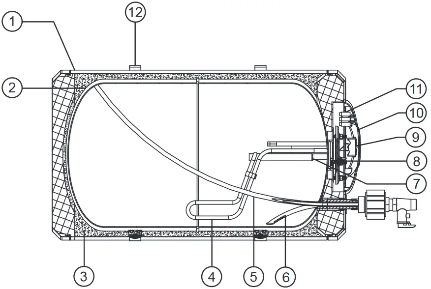
| 1. Mild Steel Casing 2. Enamel Coating Tank 3. Polyurethane Insulation 4. Heating Element 5. Hot Water Pipe 6. Cold Water Pipe | 7. Anti-corrosion Anode Rod 8. Thermal Cut-out 9. Thermostat 10. Maintenance Cover 11. Terminal Block 12. Mounting Bracket |
GENERAL INFORMATION
Electrical
a. The heater must be permanently connected to the electricity supply through a double-pole-linked switch with a contact separation of at least 3mm in all poles incorporated in the circuit and out of reach from the person using the shower.
b. The use of a plug and socket is not allowed.
c. The appliance must be earthed.
d. All wiring must conform to local regulations. If in doubt, please consult a qualified electrician. The ideal connection is shown in the diagram below.
e. Do not use undersized cables. The following table provides as reference for cable selection.
| Voltage | Power | Current | Recommended Conductor Size | Fuse / MCB | On/Off Switch |
| 240V 50/60 Hz | 3.0 kW | 12.5 A | 4.0 mm2 | 20 A | 20 A |
Water
The unit is built to operate at both high and low household water pressures and is capable of supplying hot water to one or more outlets. The minimum working pressure is 0.02 MPa and the maximum is 0.8 MPa.
Heating Time
| Model | Capacity (Litre) | Time taken to heat up to 75 °C (min.) | No. of user |
| AST-30-H | 30 | 35 | 1 – 2 |
| AST-40-H | 40 | 46 | 1 – 2 |
| AST-50-H | 50 | 58 | 1 – 3 |
| AST-60-H | 60 | 70 | 2 – 3 |
| AST-70-H | 70 | 81 | 2 – 3 |
| AST-80-H | 80 | 93 | 3 – 4 |
| AST-90-H | 90 | 105 | 3 – 4 |
INSTALLATION PROCEDURE
IMPORTANT
- The installation of electrical and plumbing work must be carried out by qualified personnel, according to the installation instructions and in compliance to the local authority regulations.
- All plumbing work must be completed and heater tank must be fully filled with water before proceeding to electrical connections. This will prevent any damage to the heating element.
- This appliance must be installed indoors only.
- Do not use ABS or PVC plastic pipes for the inlet and outlet connections.
Use only recommended stainless steel, copper or polymer pipes which can withstand high temperature and pressure. - The unit has to be installed as near as possible to the service points, in order to reduce heat loss along the pipes. To facilitate maintenance, allow a distance of 500mm for easy access to the electrical parts.
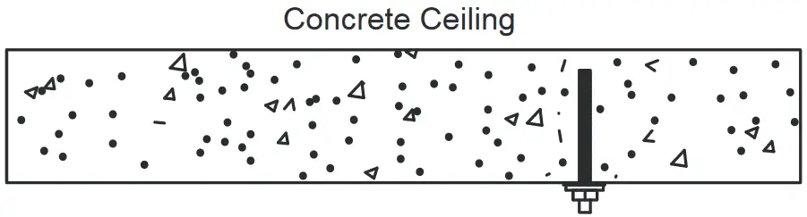
- The Storage Water Heater should be mounted on a solid cement wall, preferably close to the power source and water source. The concrete ceiling or wall must withstand 3 times the weight of the water heater fully filled with water.
Positioning of Heater
This model MUST be mounted in a horizontal position. Refer to the Mounting Guide Diagram on the next page.
Locate a suitable position for easy installation and future maintenance. Before determining the bolt’s hole position, ensure that the heater is more than 200mm from the ground or ceiling board.
After selecting the proper fixing position, drill holes and insert the expansion bolts firmly into the holes.
A set of mounting brackets are provided to achieve flexible mounting positions for concrete wall, ceiling or floor mounting, depending on site requirements.
a. For concrete wall mounting, secure Mounting Bracket (2 pcs) to heater tank. Position the heater (with Mounting Bracket) by hooking it to the L-shape Expansion Bolts (2 pcs) on the wall.
b. For concrete floor mounting, secure Mounting Bracket (2 pcs) to heater tank. Position the heater (with Mounting Bracket) and tighten the Expansion Bolts (4 pcs).
c. For concrete ceiling, secure U-shape Mounting Bracket (2 pcs) to heater tank. Position the heater (with U-shape Mounting Bracket) and tighten the Expansion Bolts (4 pcs).
Mounting Guide Diagram
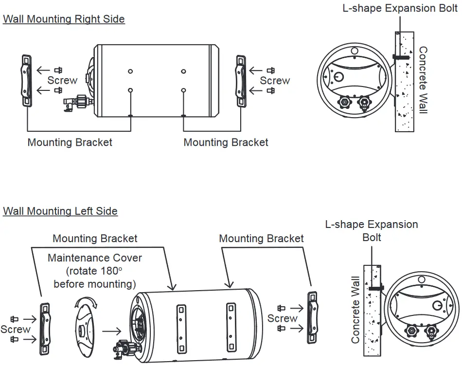 | 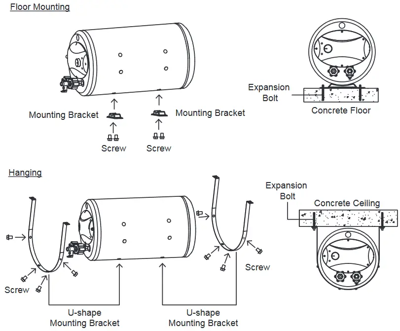 |
Plumbing
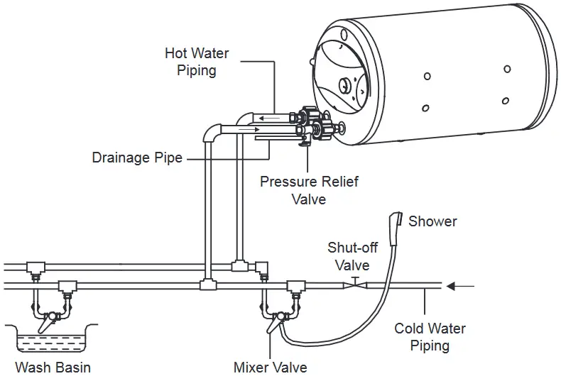
a. Connect the incoming cold water supply to the inlet of the heater i.e. at the Pressure Relief Valve (Blue).
Caution: The Pressure Relief Valve is a safety device that prevents excessive build-up of water pressure in the heater tank. It must not be removed or replaced. A discharge pipe connected to the Pressure Relief Valve is to be installed in a downward direction and in a frost-free environment. In abnormal conditions where the pressure gets higher than 0.8 MPa, water will drip from the discharge pipe of the Pressure Relief Valve. This pipe must be left open to the surrounding air.
b. Connect the outflowing hot water line to the outlet of the heater (Red).
c. Connect a PVC Hose to the Discharge Pipe of the Pressure Relief Valve at one end and the other end downward to a drain or a place where water can be discharged in the event of excessive build-up of water pressure in the tank.
d. Turn on the shut-off valve at the inlet connection and all outlet tap fittings to fill up the heater tank with water. There will be steady flow of water out of the outlet fittings when the heater tank is full.
e. Connect the water heater’s inlet and outlet with pipes or fittings that are resistant to the working pressure as well as to the hot water temperatures that usually exceed 80 degree celcius. We advise against the use of materials that cannot handle such conditions.
f. Make sure all pipes are clean before installing the tap fittings. Do not over tighten the safety valve and pipes as this may cause damage to the valve and pipe joints.
Electrical
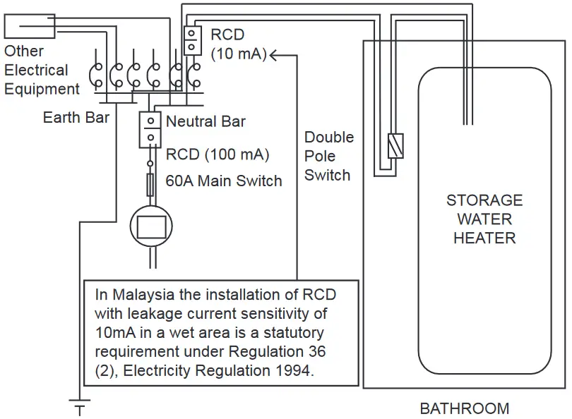
Caution: All plumbing works should be completed first before proceeding to electrical wiring connections. The heater must be used in conjunction with an approved type of RCD 10mA sensitivity.
a. Switch off the electrical supply.
b. Remove the maintenance cover.
c. Insert the electrical cable through the maintenance cover. Ensure that all cables are fully tighten to the terminal block. Connect cables as follows:
RED or BROWN …………………………………………………… LIVE ( L )
BLACK or BLUE …………………………………………………… NEUTRAL ( N )
GREEN / YELLOW or YELLOW / GREEN ……………….. EARTH (![]() )
)
d. Replace the connector cover and tighten the screws.
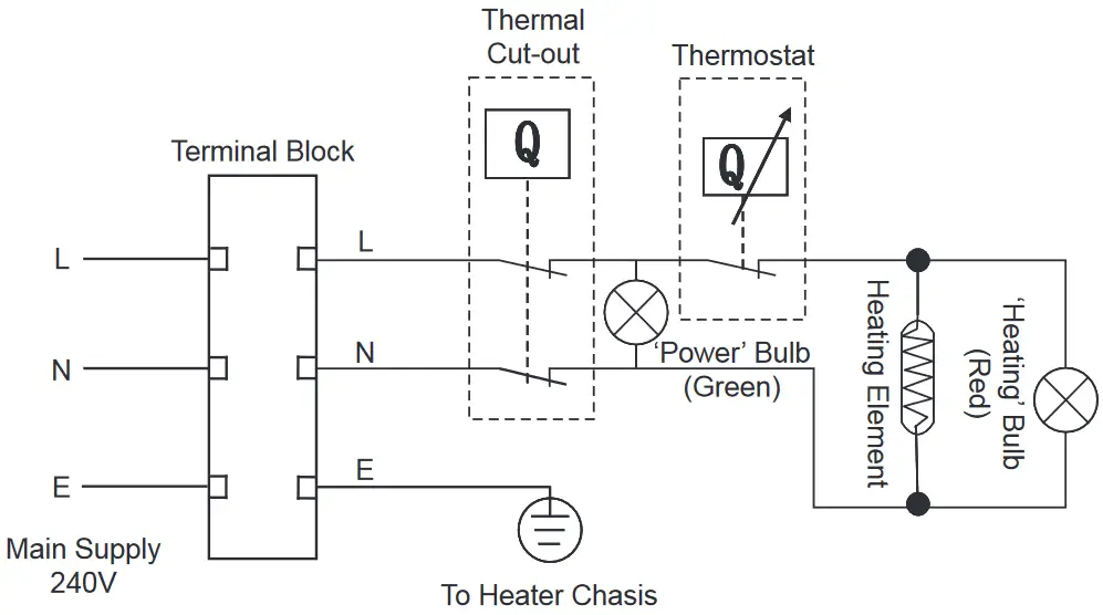
Schematic Wiring Diagram
TECHNICAL SPECIFICATIONS
| Electrical Loading | 3.0 kW 240V ~ 50/60 Hz |
| Working Pressure | min. 0.02 MPa (0.2 bar) max. 0.8 MPa (8.0 bar) |
| Water Connection | 15mm dia. (1/2” BSP) |
| Water Temperature Control | Thermostatically Controlled at 25ºC-75ºC, Safety Cut-Out at 93ºC |
| Insulation Material | CFC-Free Polyurethane Foam |
| Outer Casing Material | Epoxy Coated Mild Steel |
| Inner Tank Material | Blue Diamond Enamel Coated Mild Steel |
| Water Proof Protection | IPX4 |
Dimension
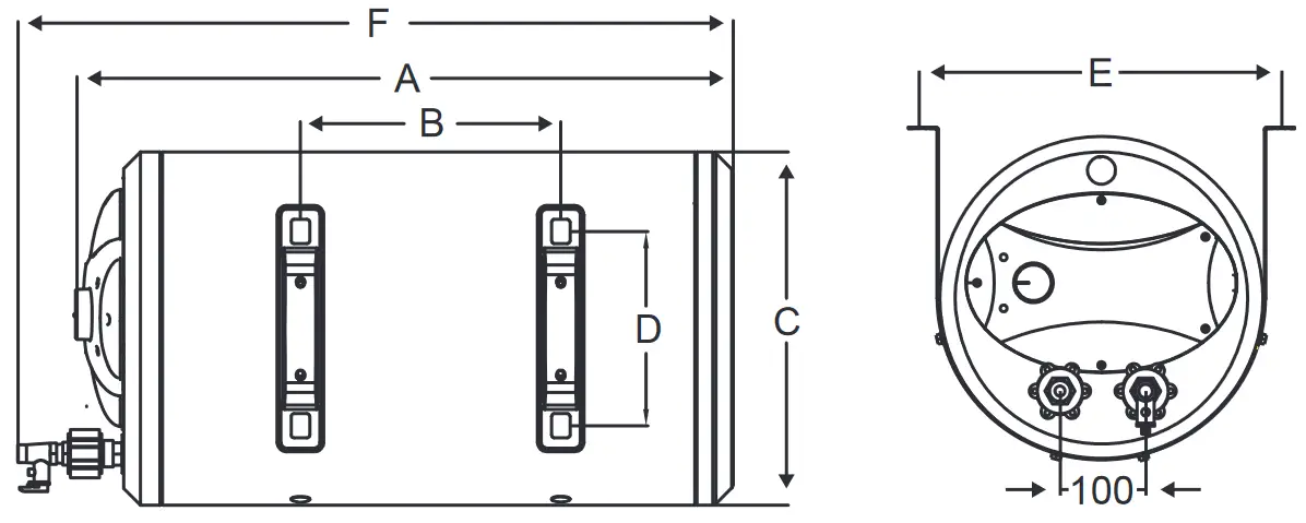
| Model | Tank Capacity (Litre) | Dimension (mm) | Approx. Weight (kgs) | ||||||
| A | B | C | D | E | F | Empty | Full | ||
| AST-30-H | 30 | 540 | 165 | φ380 | 210 | 420 | 620 | 15 | 45 |
| AST-40-H | 40 | 640 | 280 | φ380 | 210 | 420 | 720 | 18. | 58. |
| AST-50-H | 50 | 740 | 280 | φ380 | 210 | 420 | 820 | 19 | 69 |
| AST-60-H | 60 | 860 | 500 | φ380 | 210 | 420 | 940 | 22 | 82 |
| AST-70-H | 70 | 970 | 500 | φ380 | 210 | 420 | 1050 | 23.5 | 93.5 |
| AST-80-H | 80 | 970 | 400 | φ410 | 210 | 450 | 1050 | 25 | 105 |
| AST-90-H | 90 | 1055 | 400 | φ410 | 210 | 450 | 1135 | 27 | 117 |
OPERATING INSTRUCTIONS
Warning: Always ensure that the heater tank is fully filled with water (especially after installation, servicing/repairs or interruptions of water supply) before switching on the electrical supply.
a. Switch on the heater switch. The ‘POWER’ (Green) and ‘HEATING’ (Red) will light up, indicating that the heating element is heating up the water.
b. Adjust the temperature knob clockwise for higher temperature and anti clockwise for lower temperature. When the water temperature reaches approximately 70 degree celsius, the ‘HEATING’ (Red) will no longer light up, indicating that the Automatic Temperature Control System has switched off the heating element.
c. The water heater needs to be turned on for a certain period of time to reach to the acceptable temperature. For more detailed information, please refer to the table about Heating Time on Page 5.
d. It is good practice to switch off the heater switch when the heater is not in use for long periods of time.
During the heating process, it is normal to see water dripping at the safety valve. Do not cover up the safety valve outlet hole. The safety valve is to be operated regularly (preferably at least once every six months) to remove lime deposit and ensure no blockage.
MAINTENANCE
Over a long period of use, the internal parts of the heater tank that are in contact with hot water have a tendency to accummulate lime scale. To ensure proper functioning of the heater, it is important that the lime scale be removed from the Heating Element & Pressure Relief Valve. It is also recommended to check the depletion of the Anti-corrosion Anode Rod periodically.
- The power of the heater needs to be switched off for the tank to cool down.
Users should be careful when handling drained water that can be hot and cause scalding. - To discharge the water completely from the tank, remove the safety valve from the water heater.
Note : It is recommended that periodic maintenance be carried out at least once a year by qualified personnel.
TROUBLESHOOTING GUIDE
| Symptom | Cause | Solution |
| Indicator light does not light up | 1. The power source is not connected or badly connected. 2. Indicator failure. 3. Thermostat cut-off. | Get a professional technician to check the electrical wiring and indicators. |
| No hot water | 1. The heating element is defective. 2. Temperature controller malfunction. 3. No power supplied to water heater. | 1. Replace the heating element. 2. Repair/replace temperature controller. 3. Check power supply. |
| No water from the hot water tap | Main water valve not turned on. | Turn on the main water valve. |
| Leaking | 1. Leaking from plumbing connection. 2. Leaking from product. | 1. Contact qualified plumber. 2. Contact customer service. |
| Electrical mains tripped | Heating element failure. | Replace heating element. |
CUSTOMER SERVICE CENTRE
If you need any technical assistance or want to file a faulty report, please contact our customer service centre at :
Alpha Home Appliances Sdn. Bhd. (390258-H)
Head Office : 6, Jalan Sungai Kayu 32/37, Berjaya Park, Sect 32,40460
Shah Alam, Selangor.
Tel : 03-5740 6666
Fax : 03-5740 8220
Website: www.alphamalaysia.com
Email : [email protected]
Johor: 71, Jalan Molek 3/10, Taman Molek, 81100 Johor Bahru.
Tel : 07-353 4833 / 4933
Fax : 07-355 4233
Melaka: 19, 19-1 & 19-2, Jalan KSB 11, Taman Kota Syahbandar, 75200 Melaka.
Tel : 06-292 2398 / 2399
Fax : 06-292 2392
Perak: 16, Jalan Tasek Timur, Taman Tasek Indra, 31400 Ipoh, Perak.
Tel : 05-545 2282 / 547 2282
Fax : 05-547 6282
Penang: 28 Jalan Icon City, Icon City, 14000 Bukit Mertajam, Pulau Pinang.
Tel: 04-506 2366 / 2066 / 2566
Fax : 04-506 2966
Pahang: A131, Jalan Dato Wong Ah Jang, Taman Liza, 25100 Kuantan, Pahang.
Tel: 09-516 5226
Fax : 09-513 9226
Version: 2022 V1


