![]() CO2 Module Controller Universal Gateway
CO2 Module Controller Universal Gateway
User Guide
Electric Installation
Below is an illustration of the external connections that can be made in the remote control assembly.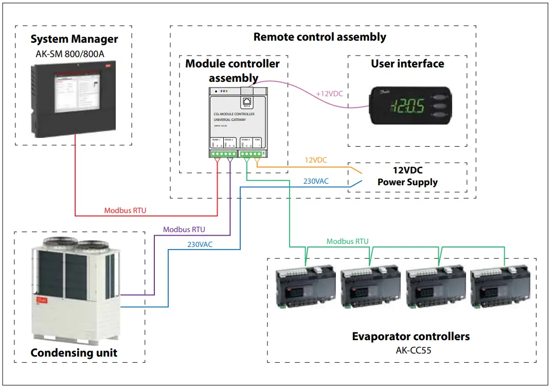
Power supply to CDU
230V AC 1,2m cable for this is included.
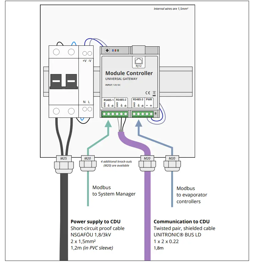
Connect Module controller power supply cable to L1 (left terminal) and N (right terminal) of the condensing unit control panel – power
supply terminal block
Caution: If the cable needs to be replaced, it must either be short-circuit proof or it must be protected by a fuse on the other end.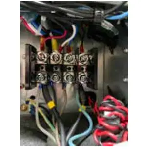
RS485-1
Modbus interface for connection to the System Manager
RS485-2
Modbus interface for connection to the CDU.
1,8 m cable for this is included.
Connect this RS485-2 Modbus cable to terminal A and B of the condensing unit control panel – Modbus interface terminal block. Do not connect insulated shield to ground 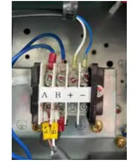
RS485-3
Modbus interface for connection to the evaporator controllers
3x LED Function explanation
- Blue led is ON when the CDU is connected and polled operation is complete
- Red led is flashing when there is a communication fault with an evaporator controller
- Green led is flashing during communication with an evaporator controller The green LED next to the 12V power supply terminals indicates “Power OK”.
Electric noise
Cables for data communication must be kept separate from other electric cables:
– Use separate cable trays
– Keep a distance between cables of at least 10 cm.
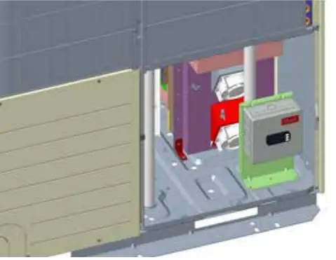
Mechanical Installation
- Installation in the backside of the unit / backside of e-panel with provided rivets or screws (3 mounting holes provided)
Procedure:
- Remove CDU panel

- Mount the bracket with provided screws or rivets
- Fix the e-Box to the bracket (4 screws provided)
- Route and connect the provided Modbus and power supply cables to the CDU control panel
- Route and connect the evaporator controller Modbus cable to the Module controller
- Option: Route and connect the System Manager Modbus cable to the Module controller
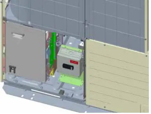
Optional installation on the frontside (only for 10HP unit, just beside the CDU control panel, holes to be drilled)
Procedure:
- Remove CDU panel

- Mount the bracket with provided screws or rivets
- Fix the e-Box to the bracket (4 screws provided)
- Route and connect the provided Modbus and power supply cables to the CDU control panel
- Route and connect the evaporator controller Modbus cable to the Module controller
- Option: Route and connect the System Manager Modbus cable to the Module controller
Module Controller wiring
Please wire the communication cable from the top of the control bord to the left side. The cable comes along with the module controller.
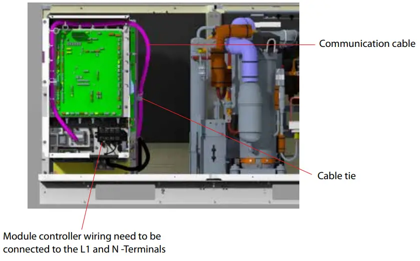
Please pass the power cable through the insulation at the bottom of the control box.
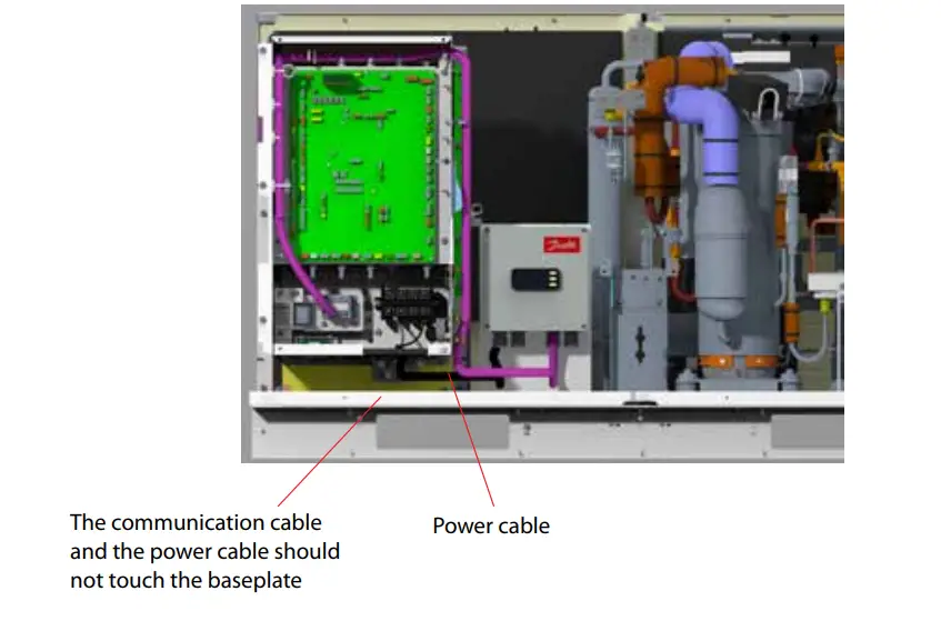
Note:
The cables should be fixed with the cable ties and should not touch the baseplate to avoid water ingress.
Technical data
| Supply voltage | 110-240 V AC. 5 VA, 50 / 60 Hz |
| Display | LED |
| Electrical connection | Power supply: Max.2.5 mm2 Communication: Max 1.5 mm2 |
| -25 — 55 °C, During operations -40 — 70 °C, During transport | |
| 20 – 80% RH, not condensed | |
| No shock influence | |
| Protection | IP65 |
| Mounting | Wall or with included bracket |
| Weight | TBD |
| Included in the package | 1 x Remote control assembly 1 x Mounting bracket 4 x M4 screws 5 x Inox rivets 5 x Sheet metal screws |
| Approvals | EC Low Voltage Directive (2014/35/EU) – EN 60335-1 EMC (2014/30/EU) – EN 61000-6-2 and 6-3 |
Dimensions
Units in mm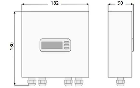
Spare parts
| Danfoss Requirements | |||||||
| Parts Name | Parts No | Gross weight | Unit Dimension (mm) | Packing Style | Remarks | ||
| Kg | Length | Width | Height | ||||
CO2 MODULE CONTROLLER UNIVERSAL GATEWAY
| MODULE CONTROLLER | 118U5498 | TBD | 182 | 90 | 180 | Carton box |
Operation
Display
The values will be shown with three digits.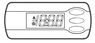
| Active alarm (red triangle) | |
| Scan for Evap. controller is in progress (yellow clock) |
When you want to change a setting, the upper and the lower button will give you a higher or lower value depending on the button you are pushing. But before you change the value, you must have access to the menu. You obtain this by pushing the upper button for a couple of seconds – you will then enter the column with parameter codes. Find the parameter code you want to change and push the middle buttons until value for the parameter is shown. When you have changed the value, save the new value by once more pushing the middle button. (If not operated for 10 seconds, the display will change back to showing the suction pressure in temperature).
Examples:
Set menu
- Push the upper button until parameter code r01 is shown
- Push the upper or the lower button and find that parameter you want to change
- Push the middle button until the parameter value is shown
- Push the upper or the lower button and select the new value
- Push the middle button again to freeze the value.
See alarm code
A short press of the upper button
If there are several alarm codes they are found in a rolling stack.
Push the uppermost or lowermost button to scan the rolling stack.
Set point
- Push upper button until display shows parameter menu code r01
- Select and change par. r28 to 1, which defines the MMILDS UI as the reference set device
- Select and change par. r01 to the required lower pressure setpoint target in bar(g)
- Select and change par. r02 to the required upper pressure setpoint target in bar(g)
Remark: The arithmetic middle of r01 and r02 is the target suction pressure.
Get a good start
With the following procedure you can start regulation as soon as possible.
- Connect the modbus communication to CDU.
- Connect the modbus communication to evaporator controllers.
- Configure the address in each evaporator controller.
- Perform a network scan in the module controller (n01).
- Verify that all evap. controllers have been found (Io01-Io08).
- Open parameter r12 and start the regulation.
- For connection to a Danfoss System Manager
– Connect the modbus communication
– Set the address with parameter o03
– Perform a scan in the System Manager.
Survey of functions
| Function | Parameter | Remarks |
| Normal display | ||
| The display shows the suction pressure in temperature. | ||
| Regulation | ||
| Min. Pressure The lower setpoint for suction pressure. See instructions for CDU. | r01 | |
| Max. Pressure The upper set point for suction pressure. See instructions for CDU. | r02 | |
| Demand Operation Limits the compressor speed of the CDU. See instructions for CDU. | r03 | |
| Silent Mode Enable/disable silent mode. Operating noise is suppressed by limiting the speed of the outdoor fan and compressor. | r04 | |
| Snow Protection Enable/disable snow protection functionality. To prevent snow from building up on the outdoor fan during winter shutdown, the outdoor fan is operated at regular intervals to blow off the snow. | r05 | |
| Main Switch Start/stop the CDU | r12 | |
| Reference source The CDU can either use a reference that is configured with rotary switches in the CDU, or it can use the reference as defined by parameter r01 and r02. This parameter configures which reference to use. | r28 | |
| For Danfoss Only | ||
| SH Guard ALC Cut-out limit for ALC control (oil recovery) | r20 | |
| SH Start ALC Cut-in limit for ALC control (oil recovery) | r21 | |
| 011 ALC setpol M LBP (AK-CCSS parameter P87,P86) | r22 | |
| SH Close (AK-CC55 parameter —) | r23 | |
| SH Setpolnt (AK-CCSS parameter n10, n09) | r24 | |
| EEV force low OD after oil recovery (AK-CCSS AFidentForce =1.0) | r25 | |
| 011 ALC setpol M MBP (AK-CCSS parameter P87,P86) | r26 | |
| 011 ALC setpoint HBP (AK-CC55 parameter P87,P86) | r27 | |
| Miscellaneous | ||
| If the controller is built into a network with data communication, it must have an address, and the system unit of the data communication must then know this address. | ||
| The address is set between 0 and 240, depending on the system unit and the selected data communication. | 3 | |
| Evaporator controller addressing | ||
| Node 1 Address Address of the first evaporator controller Will only be shown if a controller has been found during scan. | lo01 | |
| Node 2 Address See parameter lo01 | 1002 | |
| Node 3 Address See parameter lo01 | lo03 | |
| Node 4 Address See parameter lo01 | 1004 | |
| Node 5 Address See parameter 1001 | 1005 | |
| Node 6 Address See parameter lo01 | 1006 | |
| Node 7 Address See parameter 1001 | 1007 | |
| Node 8 Address See parameter lo01 Ion | ||
| Node 9 Address See parameter 1001 | 1009 |
| Function | Parameter | Remarks |
| Node 10 Address See parameter lo01 | 1010 | |
| Node 11 Address See parameter lo01 | lol 1 | |
| Node 12 Address See parameter 1001 | 1012 | |
| Node 13 Address See parameter 1001 | 1013 | |
| Node 14 Address See parameter lo01 | 1014 | |
| Node 15 Address See parameter 1001 | lo15 | |
| Node 16 Address See parameter 1001 | 1016 | |
| Scan Network Initiates a scan for evaporator controllers | nO1 | |
| Clear Network List Clears the list of evaporator controllers, may be used when one or several controllers are removed, proceed with a new network scan (n01) after this. | n02 | |
| Service | ||
| Read discharge pressure | u01 | Pc |
| Read gascooler outlet temp. | U05 | Sgc |
| Read receiver pressure | U08 | Prec |
| Read receiver pressure in temperature | U09 | Trec |
| Read discharge pressure in temperature | U22 | Tc |
| Read suction pressure | U23 | Po |
| Read suction pressure in temperature | U24 | To |
| Read discharge temperature | U26 | Sd |
| Read suction temperature | U27 | Ss |
| Read controller software version | u99 |
| Operating status | (Measurement) | |
| Push briefly (Is) the upper button. A status code will be shown on the display. The individual status codes have the following meanings: | Ctrl. state | |
| CDU not operational | SO | 0 |
| CDU operational | Si | 1 |
| Other displays | ||
| Oil recovery | Oil | |
| No communication with CDU | — |
Fault message
In an error situation an alarm symbol will flash..
If you push the top button in this situation you can see the alarm report in the display.
Here are the messages that may appear:
| Code/Alarm text via data communkation | Description | Action |
| E01 / COD offline | Communication lost with CV | Check CDU connection and configuration (SW1-2) |
| E02 / CDU communication error | Bad response from CDU | Check CDU configuration (SW3-4) |
| Al7 /CDU alarm | An alarm has occurred in the CDU | See instructions for CDU |
| A01 / Evap. controller 1 offline | Communication lost with evap. controller 1 | Check Evap. controller controller and connection |
| A02 / Evap. controller 2 offline | Communication lost with evap. controller 2 | See A01 |
| A03 / Evap. controller 3 offline | Communication lost with evap. controller 3 | See A01 |
| A04 / Evap. controller 4 offline | Communication lost with evap. controller 4 | See A01 |
| A05 / Evap. controller 5 offline | Communication lost with evap. controller 5 | See A01 |
| A06/ Evap. controller 6 offline | Communication lost with evap. controller 6 | See A01 |
| A07 / Evap. controller 7 offline | Communication lost with evap. controller 7 | See A01 |
| A08/ Evap. controller 8 offline | Communication lost with evap. controller 8 | See A01 |
| A09/ Evap. controller 9 offline | Communication lost with evap. controller 9 | See A01 |
| A10 / Evap. controller 10 offline | Communication lost with evap. controller 10 | See A01 |
| All / Evap. controller 11 offline | Communication lost with evap. controller 11 | See A01 |
| Al2 / Evap. controller 12 offline | Communication lost with evap. controller 12 | See A01 |
| A13 /Evap. controller 13 offline | Communication lost with evap. controller 13 | See A01 |
| A14 /Evap. controller 14 offline | Communication lost with evap. controller 14 | See A01 |
| A15 /Evapt controller 15 offline | Communication lost with evap. controller 15 | See A01 |
| A16 / Evapt controller 16 offline | Communication lost with evap. controller 16 | See A01 |
Menu survey
| Function | Code | Min | Max | Factory | User-Setting |
| Regulation | |||||
| Min. Pressure | r01 | 0 bar | 126 bar | CDU | |
| Max. Pressure | r02 | 0 bar | 126 bar | CDU | |
| Demand Operation | r03 | 0 | 3 | 0 | |
| Silent Mode | r04 | 0 | 4 | 0 | |
| Snow Protection | r05 | 0 (OFF) | 1 (ON) | 0 (OFF) | |
| Main Switch Start/stop the CDU | r12 | 0 (OFF) | 1 (ON) | 0 (OFF) | |
| Reference source | r28 | 0 | 1 | 1 | |
| For Da nfoss Only | |||||
| SH Guard ALC | r20 | 1.0K | 10.0K | 2.0K | |
| SH Start ALC | r21 | 2.0K | 15.0K | 4.0 K | |
| 011 ALC setpoint LBP | r22 | -6.0K | 6.0 K | -2.0 K | |
| SH Close | r23 | 0.0K | 5.0 K | 25 K | |
| SH Setpoint | r24 | 4.0K | 14.0K | 6.0 K | |
| EEV force low OD after oil recovery | r25 | 0 min | 60 min | 20 min | |
| Oil ALC setpoint MBP | r26 | -6.0K | 6.0 K | 0.0 K | |
| 011 ALC setpoint HBP | r27 | -6.0K | 6.0K | 3.0K | |
| Miscellaneous | |||||
| CDU Address | o03 | 0 | 240 | 0 | |
| Evap. controller Addressing | |||||
| Node 1 Address | lo01 | 0 | 240 | 0 | |
| Node 2 Address | lo02 | 0 | 240 | 0 | |
| Node 3 Address | lo03 | 0 | 240 | 0 | |
| Node 4 Address | lo04 | 0 | 240 | 0 | |
| Node 5 Address | lo05 | 0 | 240 | 0 | |
| Node 6 Address | 106 | 0 | 240 | 0 | |
| Node 7 Address | lo07 | 0 | 240 | 0 | |
| Node 8 Address | lo08 | 0 | 240 | 0 | |
| Node 9 Address | loO8 | 0 | 240 | 0 | |
| Node 10 Address | lo10 | 0 | 240 | 0 | |
| Node 11 Address | loll | 0 | 240 | 0 | |
| Node 12 Address | lo12 | 0 | 240 | 0 | |
| Node 13 Address | lo13 | 0 | 240 | 0 | |
| Node 14 Address | 1o14 | 0 | 240 | 0 | |
| Node 15 Address | lo15 | 0 | 240 | 0 | |
| Node 16 Address | 1o16 | 0 | 240 | 0 | |
| Scan Network Initiates a scan for evaporator controllers | nO1 | 0 OF | 1 ON | 0 (OFF) | |
| Clear Network List Clears the list of evaporator controllers, may be used when one or several controllers are removed, proceed with a new network scan (n01) after this. | n02 | 0 (OFF) | 1 (ON) | 0 (OFF) | |
| Service | |||||
| Read discharge pressure | u01 | bar | |||
| Read gascooler outlet temp. | UOS | °C | |||
| Read receiver pressure | U08 | bar | |||
| Read receiver pressure in temperature | U09 | °C | |||
| Read discharge pressure in temperature | 1122 | °C | |||
| Read suction pressure | 1123 | bar | |||
| Read suction pressure in temperature | U24 | °C | |||
| Read discharge temperature | U26 | °C | |||
| Read suction temperature | U27 | °C | |||
| Read controller software version | u99 | ||||
Danfoss A/S Climate Solutions danfoss.com • +45 7488 2222
Any information, including, but not limited to information on selection of product, its application or use, product design, weight, dimensions, capacity or any other technical data in product manuals, catalogues descriptions, advertisements, etc. and whether made available in writing, orally, electronically, online or via download, shall be considered informative, and is only binding if and to the extent, explicit reference is made in a quotation or order confirmation. Danfoss cannot accept any responsibility for possible errors in catalogues, brochures, videos and other material. Danfoss reserves the right to alter its products without notice. This also applies to products ordered but not delivered provided that such alterations can be made without changes to form, fit or function of the product.
All trademarks in this material are property of Danfoss A/S or Danfoss group companies. Danfoss and the Danfoss logo are trademarks of Danfoss A/S. All rights reserved.
© Danfoss | Climate Solutions | 2023.01


