![]()
User Manual
WisBlock
RAK5860 NB-IoT Module
Version V1.1 | June 2020
RAK5860
Introduction
This document aims to allow customers to understand quickly the RAK5860 WisIO module. The document covers schematic, electrical, and mechanical details, as well as other related information of the RAK5860 module.
Overview
2.1General description
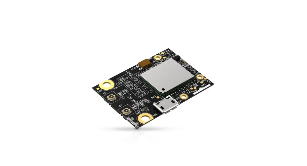
The RAK5860 WisBlock IO module was designed to be part of a production-ready IoT solution in a modular way and must be combined with a WisBlock Core and a Base module.
The RAK5860 is a module designed to work with the RAK5005-O baseboard, it provides wireless communication (LTE Cat M1, LTE Cat NB2) to the final application. This module supports the LTE-FDD network and supports half-duplex operation in the LTE network. It also provides optional GNSS functionality.
For debugging purposes, a Micro-USB connector is used for sending AT commands, data transmission, and receiving GNSS NMEA output. Once the module is integrated with the RAK5005-O baseboard, the internal UART port of the module is connected through the IO connector to a WisBlock Core module.
2.2Main Features
- Quectel BG77 with LTE Cat M1, LTE cat NB2 and GNSS
- IPEX connectors for the LTE and GPS antenna
- Micro-USB connector.
- Nano SIM and ESIM options
- Status Indication LEDs.
- Power Supply: 2.6-4.2V, typical supply voltage 3.3V
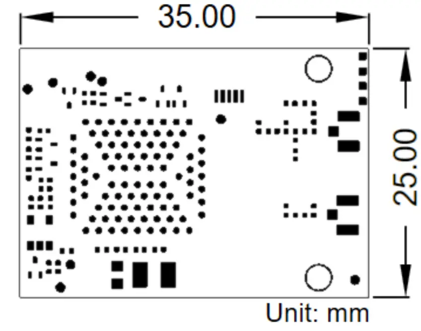
- Module size: 25mm x 35 mm
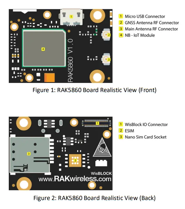
2.3Board Overview
2.4Mounting Sketch
Figure 3 shows how the RAK5860 module (a WisIO module) is integrated with the RAK5005 baseboard. The mounting sketch is shown.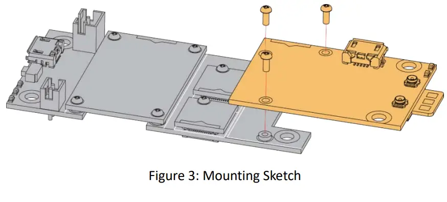 2.5IO Connector
The RAK5860 only uses a subset of all the pins available in the IO connector. These are shown in the Table below:
| Name | Description | Comment |
| VBAT | BG77 power supply | MAX 4.2V |
| 3V3_S | 3.3V for GNSS antenna | |
| 3V3 | 3.3V for a voltage-level translator. | |
| WIS_PWRKEY | Turn on/off BG77 | Active high |
| WIS_TX | UART TXD | BG77 MAIN_RX, 1.8V power domain |
| WIS_RX | UART RXD | BG77 MAIN_TX, 1.8V power domain |
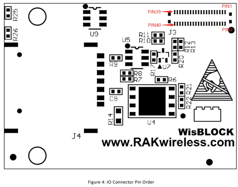
2.6IO Connector Pin order
Figure 4 shows the IO connector’s pin order. The connector is located in the bottom layer of the RAK5860 module.
Electrical Characteristics
3.1Absolute Maximum Ratings
Table below shows the absolute maximum ratings of the RAK5860 module.
| Symbol | Description | Min. | Nom. | Max. | Unit |
| VBAT | Power supply for the module | -0.5 | – | 4.2 | V |
| USB_VBUS | USB connection detection | 1.3 | – | 1.8 | V |
| Voltage at Digital Pins | -0.3 | – | 2.09 | V |
3.2Recommended Operating Conditions
Table below shows the recommended operating conditions of the RAK5860 module.
| Symbol | Description | Min. | Nom. | Max. | Unit |
| VBAT | Power supply for the module | 2.6 | 3.3 | 4.2 | V |
| USB_VBUS | USB connection detection | 1.3 | – | 1.8 | V |
| USBPHY_3P3 | Power for USB PHY circuit | – | 3.3 | – | V |
Mechanical Characteristics
4.1Board Dimensions
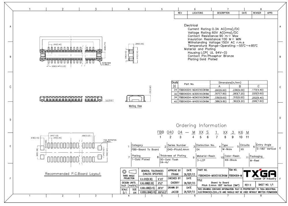
4.2WisConnector PCB Layout
CertificationInformation
FCC Caution:
Any Changes or modifications not expressly approved by the party responsible for compliance could void the user’s authority to operate the equipment.
This device complies with part 15 of the FCC Rules. Operation is subject to the following two conditions: (1) This device may not cause harmful interference, and (2) this device must accept any interference received, including interference that may cause undesired operation.
This transmitter must not be co-located or operating in conjunction with any other antenna or transmitter.
IMPORTANT NOTE:
Note: This equipment has been tested and found to comply with the limits for a Class B digital device, pursuant to part 15 of the FCC Rules. These limits are designed to provide reasonable protection against harmful interference in a residential installation. This equipment generates, uses, and can radiate radio frequency energy and, if not installed and used in accordance with the instructions, may cause harmful interference to radio communications. However, there is no guarantee that interference will not occur in a particular installation. If this equipment does cause harmful interference to radio or television reception, which can be determined by turning the equipment off and on, the user is encouraged to try to correct the interference by one or more of the following measures:
- Reorient or relocate the receiving antenna.
- Increase the separation between the equipment and receiver.
- Connect the equipment into an outlet on a circuit different from that to which the receiver is connected.
- Consult the dealer or an experienced radio/TV technician for help.
FCC Radiation Exposure Statement: This equipment complies with FCC radiation exposure limits set forth for an uncontrolled environment. This equipment should be installed and operated with minimum distance 20cm between the radiator& your body.
Revision History
| Revision | Description | Date |
| 1 | Initial version | 2020/6/3 |
| 1.1 | Review the details | 2020/6/13 |
Document Summary
| Prepared by | Checked by: | Approved by: |
| gang.chen | Tzu |
![]() www.RAKwireless.com
www.RAKwireless.com
RAK5860
Copyright© Shenzhen RAKwireless Technology Co.Ltd.


