![]()
INSTRUCTION
MANUAL
![]() WARNING!
WARNING!
This vehicle delivered a very powerful velocity.
If the handling and the instructions is not followed with all attention needed, a lot of parts can be damaged easily.
It is better to start slowly to learn how to control this amazing power!
![]() • This is not a toy! Not suitable for children under 14 years old without adult supervision.
• This is not a toy! Not suitable for children under 14 years old without adult supervision.

PROVIDED WITH THE CAR
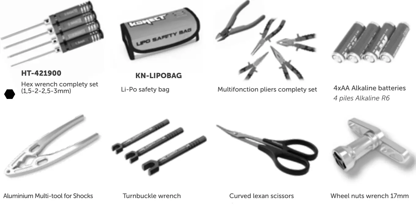
THE TOOLS REQUIRED ARE NOT INCLUDED IN THE KIT
CHASSIS
WARRANTY AND SERVICE INFORMATION
COMPONENT WARRANTY PERIOD
PLEASE READ THE FOLLOWING INFORMATION CAREFULLY!
Please note this is a high-quality hobby product and not a toy. Therefore, it is necessary that children under 14 years are supervised by an adult. The guardians and/or parents have the responsibility to provide the appropriate guidance and supervision of the minors.
This product has a 90-day warranty, which is only guaranteed to the original purchaser. The warranty is valid only for products that have been purchased from an authorized Hobbytech dealer. Warranty claims will be processed only with valid proof of purchase/receipts. If within the warranty period, a portion of the product fails due to manufacturing defects, then it is within the discretion of Hobbytech to repair it or replace it. The decision to repair or replace the part will be taken by Hobbytech. After use, we do not offer new for old warranty.
WARRANTY DISCLAIMER
This high-performance model was made with the highest attention and care and should be treated with respect. Excluded from the warranty are components that have been damaged by the wrong installation, mishandling, accident, operation, maintenance, lack of maintenance and care, as well as abuse and/or repair attempts. Furthermore excluded from the guarantee are wearing parts such as fuses and batteries, visual impairments, shipping -, and transport costs.
WARRANTY CLAIM
Please contact your dealer with the warranty claim and/or repair. Your dealer and Hobbytech will make a proper decision that will help you as soon as possible. For invalid warranty claims, you may be charged for the processing costs before the parts are returned. All repairs which are necessary by negligence or abuse are billed in advance. In case you decide that you do not want to repair your product then Hobbytech editing and reserves the right to charge shipping costs.
KONECT KT3S-NEO TRANSMITTER
FCC ID: YDTHBT1000 FCC Statement: This equipment has been tested and found to comply with the limits for Part 15 of the FCC rules. These limits are designed to provide reasonable protection against harmful interference in a residential installation.
This equipment generates, uses and can radiate radio frequency energy and, if not installed and used in accordance with the instructions, may cause harmful interference to radio communications.
However, there is no guarantee that interference will not occur in a particular installation. If this equipment does cause harmful interference to radio or television reception, which can be determined by turning the equipment off and on, the user is encouraged to try to correct the interference by one or more of the following measures:
- Reorient or relocate the receiving antenna.
- Increase the separation between the equipment and receiver.
- Connect the equipment to an outlet on a circuit different from that to which the receiver is connected.
This device complies with Part 15 of the FCC Rules. Operation is subject to the following two conditions: (1) this device may not cause harmful interference, and (2) this device must accept any interference received, including interference that may cause undesired operation.
Notice: Modifications to this product will avoid the user’s authority to operate this equipment.
DECLARATION OF CONFORMITY IN ACCORDANCE WITH THE RADIO & TELECOMMUNICATIONS TERMINAL EQUIPMENT (R&TTE) DIRECTIVE 1999/5EC.
Sarl Model
3 rue Labouche
3100 Toulouse, France
Declares that the following product :
1.BX8.RUNNER-G / O
w/ KONECT KT3S-NEO Transmitter & Receiver
Item Number: KN-KT3S-NEO/SET
Equipment class: 1
Complies with the essential requirements and other relevant provisions of the FTEG (Article 3 of the R&TTE directive)
- Protection of health and safety of the user and any other person, (article 3.1a of the Directive)
Standards applied: EN 62311:2008 - The essential requirements of the Electromagnetic Compatibility Directive (article 3.1b)
Standards applied:
EN 301 489-1 V1.9.2 (2011-09)
EN 301 489-3 V1.4.1 (2002-08) - Effective use of the radio spectrum/orbital resource so as to avoid harmful interference
(article 3.2).
Standards applied:
EN 300 440-1 V1.6.1 (2010-08)
EN 300 440-1 V1.4.1 (2010-08)
Manufacturer Address:
Sarl Imodel
3 rue Labouche
31100 Toulouse
France
Date of issue: September 27, 2012


 This product must not be disposed of with other waste. Instead, it is the user’s responsibility to dispose of their waste equipment by handing it over to a designated collection point for the recycling of waste electrical and electronic equipment. The separate collection and recycling of your waste equipment at the time of disposal will help to conserve natural resources and ensure that it is recycled in a manner that protects human health and the environment.
Help us to protect the environment and respect our resources!
IMPORTANT – READ THIS BEFORE RUNNING
Please READ All INSTRuCTIONS AND FAMIlIARIzE YOuRSElF WITh ThE PRODuCTS AND CONTROl BEFORE OPERATION.
This product is not a toy. It is a high-performance model product. It is important to familiarize yourself with the model, its manual, and its construction before assembly and operation. Adult supervision is necessary
CAUTION
To avoid serious personal injury and property damage, operate all remotely controlled models in a responsive manner as outlined below.
R/C car models can exceed speeds of 40km/h (25mph), and cannot be stopped quickly.
❶ Never run R/C models on the street or highways, as it could cause or contribute to serious traffic accidents.
❷ Never run an R/C model near people or animals, nor use people or animals as obstacles when operating R/C vehicles.
❸ To avoid injury to persons or animals, and damage to property, never run an R/C model in a confined or crowded area.
❹ Running R/C models into furniture or other inanimate objects will cause damage to the objects and the R/C models.
CAUTION DURING OPERATIONS
When the R/C model is in operation, dot not touch any of its moving parts, such as drive shafts, and wheels, as the rotating parts can cause serious injury.
❶ The vehicle motor gets very hot during running and could cause burns if touched.
❷ Make sure that no one else is using the same frequency as yours in your running area. Using the same frequency at the same time, whether is driving, flying, or sailing, can cause a loss of control of the R/C models, resulting in serious accidents.
❸ Properly connect plugs. To prevent electrical shock and/or damage to the product resulting from a short-circuit; insulate connections with heat shrink tubing or electrical tape. Before running the vehicle, check that battery wiring and plugs are not so loose as to drag on the ground. Properly secure cables using electrical tape or nylon tie-wraps.
❹ Stiff rotation of gears, shafts, joints, and wheels can burn out the motor. It’s recommended to check proper joint and shaft rotation by using one 1,5V dry cell during the assembly of the model. A worn motor will overheat and result in a short running time. Replace a worn-out motor as soon as possible.
❺ R/C models will run out of control when either the receiver or the transmitter battery voltage drops off. Stop the vehicle immediately when the car starts to slow down to prevent it from running out of control.
SAFETY PRECAUTIONS
Follow the outlined rules for safe radio control operation. Avoid running the car in crowded areas and near small children. Make sure that no one else is using the same frequency in your running area. Using the same frequency at the same time can cause serious accidents, whether it’s driving, flying, or sailing. Avoid running in standing water and rain. If the R/C unit, motor, or battery gets wet, clean and dry thoroughly in a dry shaded area. R/C operating procedures
❶ Make sure the transmitter controls and trims are neutral. Switch on the transmitter.
❷ Switch on the receiver.
❸ Inspect operation using transmitter before running.
❹ Adjust steering servo and trim so that the model runs straight with the transmitter in neutral.
❺ Reverse sequence to shut down after running.
❻ Make sure to disconnect/remove all batteries.
❼ Completely remove sand, mud, dirt, etc
❽ Store the car and batteries separately when not in use
SETTING UP THE MODEL
To greatly enhance the overall performance of your car, it’s necessary to tune the vehicle to the track (and its surface conditions) on which you will be racing. Make adjustments referring to the instruction manual, keeping in mind that “balance” is the keyword.
❶ Tires
Tires have a great influence on the performance of your car and are normally the first components tuned. Select the right tires
for the track you are racing on.
❷ Toe-in and Toe-out
Adjusting the car toe-in a little, by pointing the wheel inwards, provides the car with good straight running and moderate steering characteristics. Toe-out, which point the wheels outwards, gives sharp and crisp steering. Take care not to overdo it.
❸ Camber angle
While taking the corners, the car is forced to go outwards, causing instability. The area of contact on each tire is determined by the camber angle, and therefore the traction of the tires can be made greater or lesser by adjusting of camber angle. To increase traction during cornering, adjust the camber angle negative, and reduce traction, adjust for positive camber.
❹ Ground clearance and suspension drop
Ground clearance and/or rebound stroke has a great effect on stability during cornering, acceleration, and braking. The ground clearance can be adjusted by altering damper spring tension and stiffness.
❺ Gear ratio
Proper gear ratio should be determined by the available output power of the motor; type of battery; track condition and layout It should be also noted that running the car on a good grip surface suggests the use of a pinion gear 1 tooth smaller, in order to effectively use all of the available battery power.
EVEN IF THIS CAR IS A READY-TO-RUN KIT, YOU STILL HAVE SOME LITTLE THINGS TO DO TO FAMILIARI ZE WITH YOUR
PRODUCT. PLEASE FOLLOW THESE STEPS.
For obvious reasons of security, the KONECT KT3S+NEO radio system is equipped with an automatic power shut down of the receiver when the user turns the transmitter On while turning the steering wheel or touching the throttle trigger.
Consequently, on the ignition, the vehicle won’t (for example) unintentionally accelerate. The transmitter Led flashes red, and the user cannot use it anymore. Then it must be turned Off and On without touching anything else.
Functions
KT3S+NEO Transmitter
Steering Wheel: Control direction (Left / Right) of the RC model
Throttle Trigger: Control speed and direction (Forward/Brake/Backward) of the driving model.
Battery Compartment Tray: Cover and hold the batteries powering the transmitter.
Antenna: Transmit signal to the model
Power ON / OFF: Power ON / OFF the transmitter
SYNC & Battery Indicator: Top Green LED light indicates synchronization status and/or adequate battery power supply.
Switch: Every impulse controls CH3
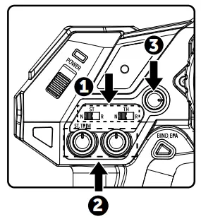
ATV: Adjustable Steering Rate by ATV dial
ST. Trim Dial: Adjust the neutral position of the steering servo when model wheels are straight ahead.
TH. Trim Dial: Make sure the model stays still when releasing the throttle trigger.
BIND: Pairing EPA: End Point Adjustment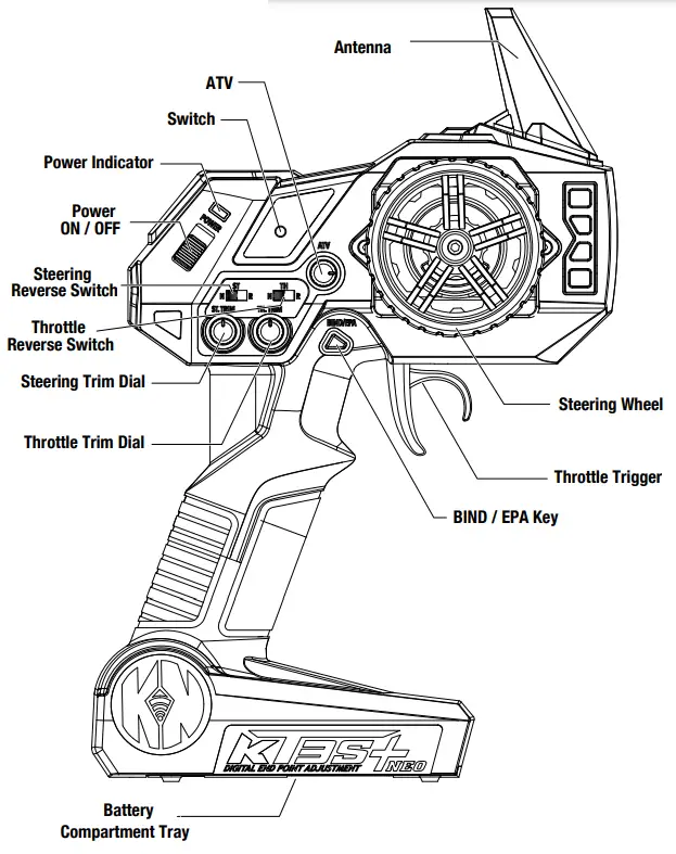 WARNING: Accidentally or intentional EPA function manipulation may cause servos malfunction (reduced or inexistent travel). Please reset maximum default values before contacting your dealer (see ).5
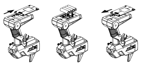
Battery Installation
| Works with 4 x 1.5V AA Batteries (not provided), KT3S+NEO can be operated a few hours. Installation: Remove the battery compartment cover as shown below. | Install the batteries observing the polarity marked on the battery compartment. | Then red compartment cover as the picture shown below. |
 | ||
Warning: Never disassemble batteries or put the batteries in fire, chemical agents, otherwise they may cause personal injuries or property damages.
Battery Disposal: Observe corresponding regulations about wasted battery treatment regulations.
- After running out of power, dispose of wasted batteries in designated areas far away from the water supply, household areas, and planted areas.
- Submit the wasted batteries to specific recycling stations.
Battery LED Indicator
– During normal operation, the LED should be solid green ON-
– When the battery voltage is dropped below 3.8V, the LED will become red color, to indicate the battery is low, you should replace the new battery as soon as possible
Pre-Run Check
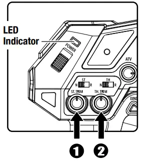
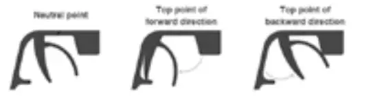
- Steering: Adjust the steering trim to keep the front wheels in a straight line when the steering wheel remains in a NEUTRAL position.
- Throttle: Adjust the throttle trim to ensure the wheels stop rotating when the throttle trigger remains in the NEUTRAL position (only for nitro). For EP vehicles, this button must be set to NEUTRAL (calibrate the NEUTRAL with ESC).
* Always turn on the transmitter first by sliding the switch on the left side from bottom to top. The green lights above the switch should light up. If not, you
need to check for low or incorrectly installed batteries.
BIND
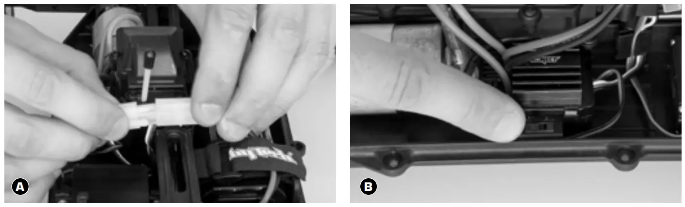
Pairing your receiver to your KT3S+
Place the model on a block to prevent the wheels from touching the ground.
A Connect battery to ESC. Fix the wire correctly with the provided connectors.
You must check the signal of the transmitter and receiver before you operate it at first.
Make sure TH Trim is on neutral
– TURN OFF THE TRANSMITTER AND RECEIVER –
- Transmitter turned off, power the receiver On B (via ESC). The receiver LED flashes Red.
- Press and Hold the «BIND/EPA» transmitter button while powering On the transmitter C.
The receiver LED becomes solid Red, and the transmitter solid green: your receiver is paired with your transmitter. You can release the «BIND/EPA» button.
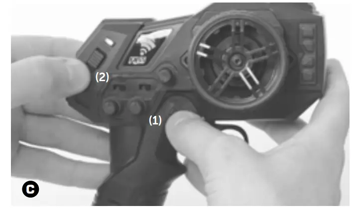
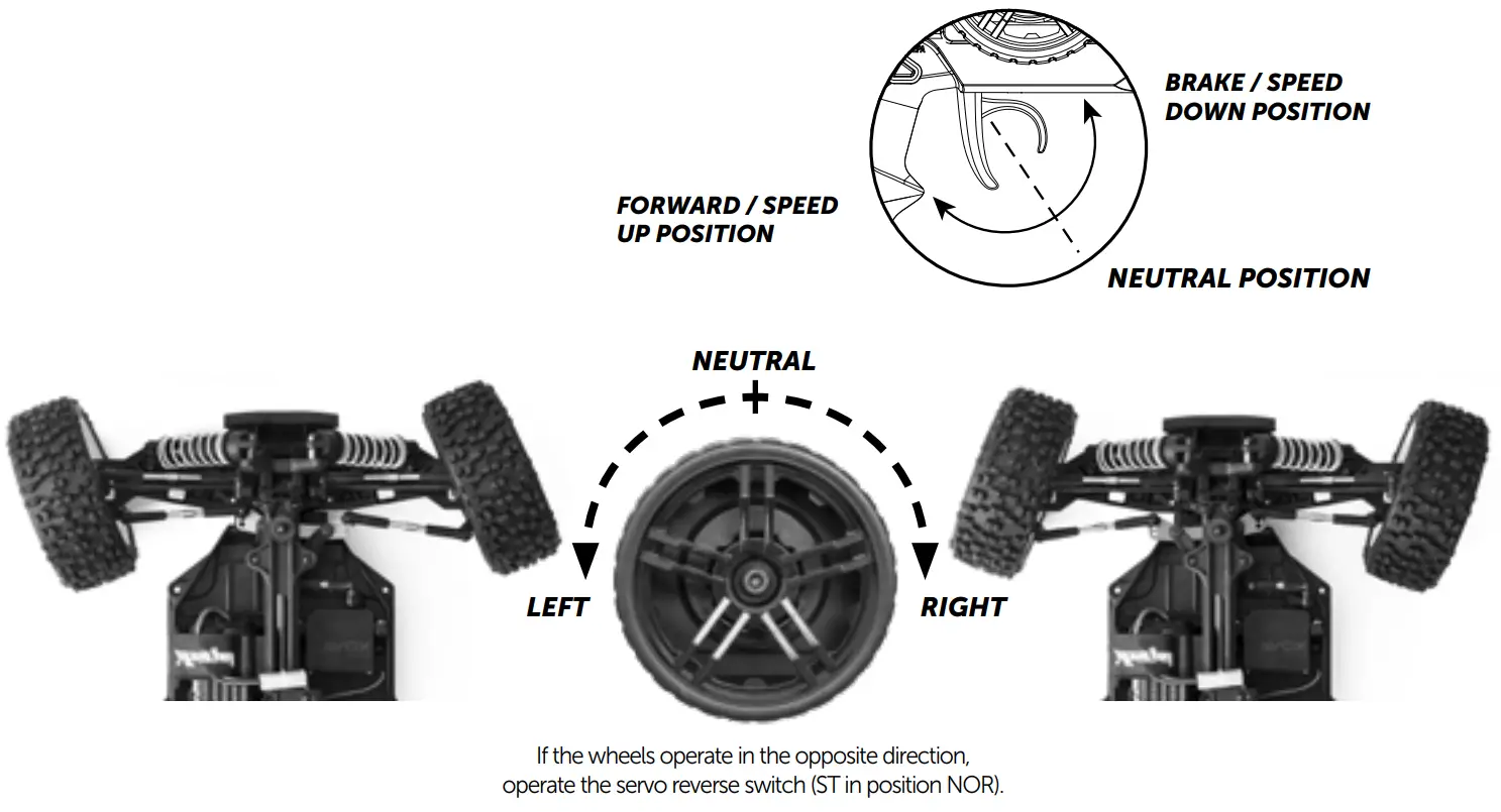
HOW TO CONTROL YOUR MODEL
- Pull up the trigger in order to brake or speed down
- Pull the trigger in order to go forward or speed up
ABOUT THE RADIO SYSTEM
1 Set up your Radio
ABOUT THE RADIO SYSTEM
Pairing your receiver to your KT3S+NEO
- Transmitter turned off, power the receiver On. The receiver LED flashes Red
- Press and Hold the «BIND/EPA» transmitter button while powering On the transmitter.
The receiver LED becomes solid Red, and the transmitter solid green: your receiver is paired with your transmitter. You can release the «BIND/EPA» button.
2 Reversing
Reversing is used to change the response direction of the steering wheel and throttle trigger. KT3S+NE0 Transmitter features 2 reversing functions: Steering Reverse and Throttle Reverse.
Steering Reverse: Reverse the response direction when operating the steering wheel. Turning the left steering wheel, the model turns right while turning right the model turns left.
Throttle Reverse: Reverse the response direction when operating the throttle trigger. Pushing forward throttle trigger the model moves backward while pulling back, the model moves forward.
3. Trimming
KT3S+NE0 features two trimming functions: Steering Trim and Throttle Trim. Steering Trim Dial: Adjust the neutral position of the steering servo when the wheels are straight ahead. Normally steering trim is adjusted until the model can keep straight tracks.
Throttle Trim Dial: Adjust the neutral position of the throttle servo. Make sure the model stays still when releasing the throttle trigger.
4. Adjustable Steering Rate (ATV)
Adjustable Steering Rate enables to adjustment of the same maximum steering angle of the servo on both sides (Left and Right) when the model makes steering. The Adjustable Steering Rate affects the sensitivity of the servo. Reducing dual rate values can lower the sensitivity of the servo and reduce the same maximum steering angle on both sides. Remember to adjust the dual rate value within the adjustment range: rotate clockwise = increase maximum steering angle; rotate counterclockwise = reduce maximum steering angle. The minimum adjustment of the ATV (counterclockwise to the max) makes a zero steering angle.
5. End Point Adjustment (EPA)
In order to avoid mechanical strain when steering to the maximum and/or accelerating and braking (nitro), an EPA function (End Point Adjustment) can be digitally set. However, AN function can be used for steering endpoints, but on the left & right together. If you really want to use the EPA function, please read the following instructions carefully:
1. Steering servo a) Transmitter and receiver powered on (green LED on), AN turned to the maximum (clockwise), turn the steering wheel to the maximum (on the side you want to set), then press once the «BIND/EPA. button: LED turns solid red.
b) As long as LED is red, you can set the exact maximum turning angle of the wheels on the side you choose. Once the angle is chosen, press once again the «BIND/EPA. button. LED flashes 4 times green and then turns solid green.
IMPORTANT: Switch OFF and ON the transmitter to confirm the adjustment.
c) To reset the default value, follow a) step, then hold the steering wheel to the maximum and press the «BIND/EPA. button. LED flashes 4 times green and then turns solid green.
IMPORTANT: Switch OFF and ON the transmitter to confirm the adjustment.
To set the opposite side, follow 1.a) and 1.b) steps in the opposite side. It is very important to perform these operations one by one.
2. Throttle servo (EPA is recommended only for nitro vehicles) a) Transmitter and receiver powered on (green LED on), hold the throttle at the forward-most position, then press once the «BIND/EPA. button: LED tums solid red.
b) As long as LED is red, you can set the exact max throttle end-point. Once the end-point is chosen, press once again the «BIND/EPA. button. LED flashes 4 times green and then turns solid green. IMPORTANT: Switch OFF and ON the transmitter to confirm the adjustment.
c) To reset the default value, follow 2. a) step, then hold the throttle at the forward-most position, then press once the «BIND/EPA.. LED flashes 4 times green and then turns solid green.
IMPORTANT: Switch OFF and ON the transmitter to confirm the adjustment.
To set the brake, follow the 2.a) step, braking to the maximum. You can now set your maximum brake end-point. It is very important to perform these operations one by one.
40Amp BRUSHED WATERPROOF ESC – INSTRUCTION MANUAL
A high-power system for the RC model can be very dangerous, so we strongly suggest you read this manual carefully. In that HOBBYTECH have no control over the correct use, installation, application, or maintenance of our products, no liability shall be assumed nor accepted for any damages, losses or costs resulting from the use of the product. ANY CLAIMS ARISING FROM THE OPERATING, FAILURE OR MALFUNCTIONING ETC. WILL BE DENIED. WE ASSUME NO LIABILITY FOR PERSONAL INJURY, CONSEQUENTIAL DAMAGES RESULTING FROM OUR PRODUCT, OR OUR WORKMANSHIP AS FAR AS IS LEGALLY PERMITTED, THE OBLIGATION TO COMPENSATION IS LIMITED TO THE INVOICE AMOUNT OF THE AFFECTED PRODUCT.
FEATURES
- Water-proof and dust-proof for all-weather races.
- Small size with built-in capacitor module. 3. Automatic throttle range calibration, easy to use.
- Multiple protections: Low voltage cut-off protection for Lipo or NiMH battery / Over-heat protection / Throttle signal loss protection.
- Easily programmed with the jumpers.
SPECIFICATIONS
| Model | KN-BRUSH40 | |
| Cont. / Burst Current | Forward: 40A / 180A Backward: 20A / 90A | |
| Input | 2-3S Lipo, 5-9 Cells NiMH/NiCd | |
| Cars Applicable | 1:10 on-road, off-road Buggy, Truggy, SCT 1:10 Crawler, Tank & Boat | |
| Motor Limit | 2 Lipo or 5-6 NiMH | 540 or 550 size motor >12T RPM < 30000 @7.2V |
| 3 Lipo or 7-9 NiMH | 540 or 550 size motor >18T RPM < 20000 @7.2V | |
| Resistance | FWD: 0.002 Ohm BWD: 0.004 Ohm | |
| Built-in BEC | 2A/5V (Linear mode BEC) | |
| PWM Frequency | 1KHz | |
| Dimension It Weight | 46.5*34*28.5, 65g | |
BEGIN TO USE
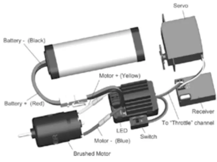
- Connect the ESC, motor, receiver, battery and servo according to the following diagram
 “+” and “-” wires of the ESC are connected to the battery pack.
ATTENTION: The incorrect polarity will damage the ESC immediately. The control cable of the ESC (trio wires with black, red and white color) is connected to the throttle channel of the receiver (Usually CH2). The “Motor +” and “Motor –” wires are connected to ESC without any order. If the motor runs in the opposite direction, please swap these two wire connections. - Set the Transmitter
Please set the “D/R”, “EPA” and “ATL” to 100% for the throttle channel (for transmitters without LCD, please turn the knobs to the maximum value), and set the “TRIM” of the throttle channel to 0 (for transmitter without LCD, please turn the TRIM knob to its neutral position).
For FutabaTM and similar transmitters, the direction of the throttle channel shall be set to “REV”, while other radio systems shall be set to “NOR”. The “Fail Save” function of the radio system is strongly recommended to be activated. Please make sure that the motor can be stopped when the “Fail Save” happens. - Throttle Range Setting (Throttle Range Calibration)
In order to make the ESC match the throttle range of different transmitters, the calibration of the ESC is necessary. To calibrate the ESC, please turn on the transmitter, keep the throttle stick at its neutral position, and wait for 3 seconds to let the ESC execute self-test and automatic throttle calibration. When the ESC is ready to run, a long beep sound is emitted from the motor. Note: Please calibrate the throttle range again when using a new transmitter or changing the settings of the neutral position of throttle channel, D/R, ATV, ATL, or EPA parameters, otherwise the ESC may not work properly.
 “+” and “-” wires of the ESC are connected to the battery pack.
BEEP SOUND AND LED STATUS
| The Meaning of Beep Sound | LED Status |
| 1 short Beep: The battery is NiMH/NiCd 2 short Beeps: The battery is 2S Lipo 3 short Beeps: The battery is 3S Lipo 1 long Beep: Self-test and throttle calibration is OK, the ESC is ready to run | When the throttle stick is in the neutral range, the red LED is off Forward, brake or reverse at partial throttle, red LED blinks Forward, brake or reverse at full throttle, red LED is solid |
THROTTLE
SET THE ESC
PROTECTION FUNCTIONS
- LOW VOLTAGE CUT-OFF PROTECTION: If the voltage of battery pack is lower than the threshold for 2 seconds, the ESC will enter the protection mode. When the car stops, the red LED blinks to indicate the low voltage cut-off protection has been activated.
2S Lipo 3S Lipo 5-9 cells NiMH Output reduces 50% at 6.5V
Output cuts off at 4.0V, and cannot be recoveredOutput reduces 50% at 9.75V
Output cuts off at 9.0V, and cannot be recoveredOutput reduces 50% at 4.5V
Output cuts off at 6.0V, cannot be recovered - OVER-HEAT PROTECTION: When the internal temperature of the ESC is higher than a factory preset threshold for 5 seconds, the ESC will reduce and cut off the output power. When the car stops, the red LED blinks to indicate that over-heat protection has been activated. If the ESC cools down to 80 Celsius degree, the output power is recovered to a normal state.
- THROTTLE SIGNAL LOSS PROTECTION: The ESC will cut off the output power if the throttle signal has been lost for 0.1 seconds.
TROUBLESHOOTING
| TROUBLE | POSSIBLE REASON | SOLUTION |
| After power on. the motor can’t work, no sound is emitted, and LED is off | The ESC doesn’t get its working voltage: Connections between the battery pack and ESC are broken | Check the battery wires connection or replace the defective connectors |
| Switch is damaged | Replace the switch | |
| Polarity or battery type is wrong | Check polarity and battery type | |
| After power on, the motor can’t work; red LED blinks | The throttle signal is abnormal | Check the throttle wire connection; make sure it is plugged into the throttle channel of the receiver |
| Automatic throttle range calibration is failed | Set the ‘TRIM’ of the throttle channel to 0 or turn the knob to its neutral position | |
| The motor runs in the opposite direction | The wire connections between ESC and the motor need to be changed | Swap two wire connections between the ESC and the motor |
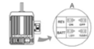
| The car can’t go backward | The jumper position is wrong | Check the jumper and plug it to the correct position |
| The neutral point of the throttle channel is changed or drifted | Set the ‘TRIM’ of the throttle channel to 0 or turn the knob to its neutral position | |
| The car can’t go forward, but can go backward | The direction of the throttle channel is not correct | Reset the direction of the throttle channel from original “NOR’ to “REV”, or from original ‘REV’ to “NOR* |
| The motor doesn’t work, but the LED in the ESC works normally | The connections between the motor and ESC are broken | Check the connections and replace the defective connectors |
| Motor is damaged | Replace the motor | |
| The motor suddenly stops running while in a working state | The throttle signal is lost Check the throttle wire connection | Check the transmitter and the receiver. |
| Low voltage cut-off protection or Over-heat cut-off protection has been activated | Replace the battery pack, or cool down the ESC | |
| The car cannot get top speed and the red LED doesn’t solid on at full throttle | Some settings in the transmitter is incorrect | Set D/R, and EPA ATL to 100% or turn the knobs to the maximum value. Set TRIM to 0 or turn the knob to its neutral position |
| Motor is cogging when accelerated quickly | The battery has limited discharge ability | Use battery with better discharge ability |
| Motor RPM is too high, the gear ratio is too aggressive | Use motor with lower RPM, or use smaller pinion to get the softer gear ratio | |
| Something wrong in the driving system of the car | Check the driving system of the car | |
| The car doesn’t run straight | Steering TRIM is not adjusted correctly | Make adjustments to the TRIM |
| Wheel nuts are too loose | Tighten wheel nuts |
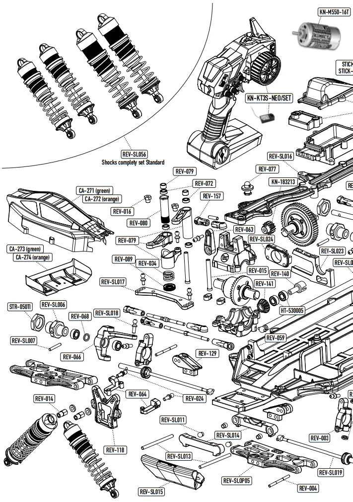
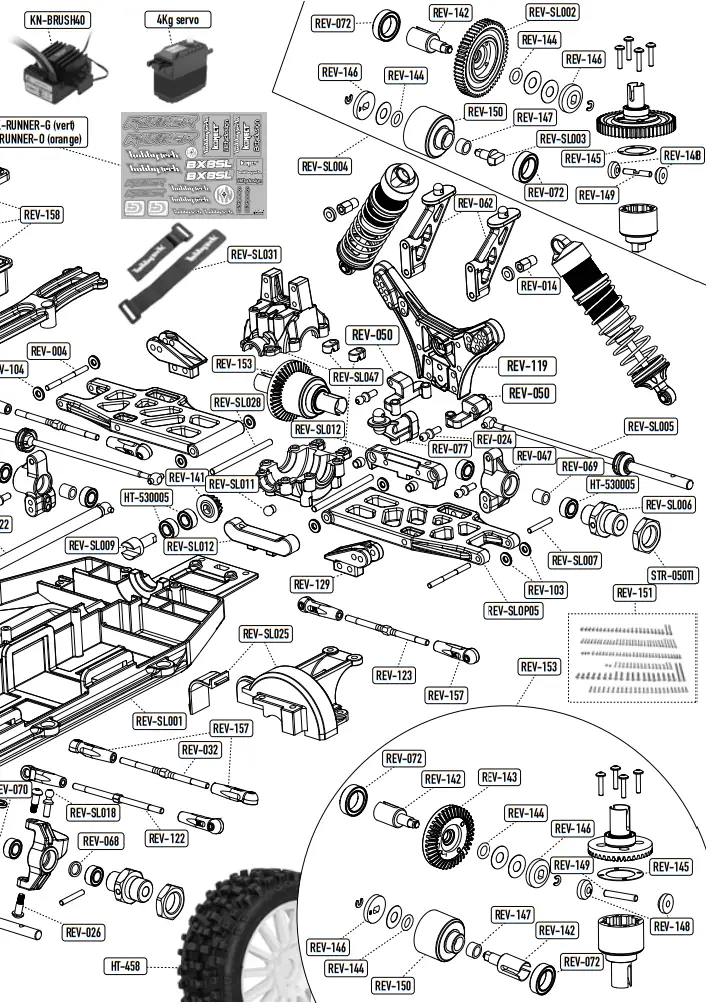
REFERENCE GUIDE
| ITEM | DESIGNATION | ITEM | DESIGNATION | ITEM | DESIGNATION |
| CA-271 | BX8SL Runner Green body | REV-077 | F/R body post | REV-SL005 | BX8SL / RX8SL CVD rear drive shaft |
| CA-272 | BX8SL Runner Orange body | REV-079 | Steering set | REV-SL006 | BX8SL / RX8SL 17mm Wheel Hub |
| CA-273 | Green BX8SL Runner prepainted wing | REV-080 | Servo saver pipe | REV-SL007 | SL wheel hub Pin |
| CA-274 | Orange BX8SL Runner prepainted wing | REV-089 | Servo saver nut | REV-SL009 | SL center diff drive couple |
| HT-458 | MAXI CROSS 1/8 Pre glued BUGGY Tyres on white spokes wheels | REV-103 | Rear hub washer | REV-SL011 | SL lower hinge pin plastic ball |
| HT-530005 | High speed bearings 5x10x4 ABEC5 x10pcs | REV-104 | Rear arm washer | REV-SL012 | SL Rear to-in plate/Lower Susp arm |
| KN-183213 | 13t pinion gear alloy steel 32dp ø5mm + 3,17 adapter | REV-115 | Shock rebuilt kit | REV-SL013 | SL Front lower Susp hinge pin |
| KN-KT3SNEO/SET | 2.4 GHZ Radio Konect KT3S-NEO | REV-118 | BX8 SL Runner Front Shocks Tower | REV-SL014 | SL Front to-in plate/Lower Susp arm |
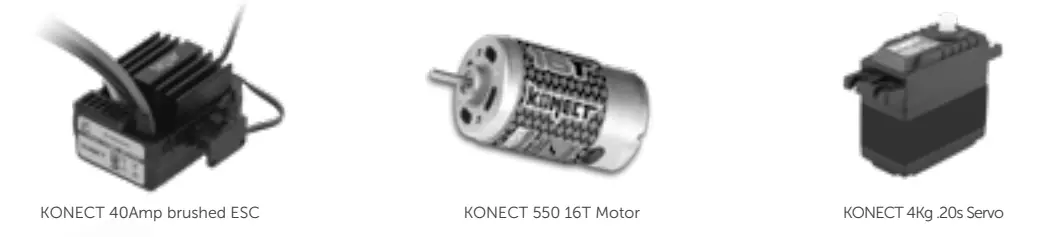
| KN-BRUSH40 | ESC waterproof 40 Amp brushed KONECT | REV-119 | Rear shocks tower SURVOLT/ ST10 | REV-SL015 | BX8L Front Bumper |
| KN-M55016T | 550 brushed KONECT motor 16T | REV-122 | Front Camber Turnbuckle ST10 | REV-SL016 | Hobbytech SL upper plate |
| REV-003 | L/R Front C-hub | REV-123 | Rear Camber Turnbuckle ST10 | REV-SL017 | Hobbytech SL Steering Plate |
| REV-004 | C-Hub Pin | REV-129 | ST10 shocks holder | REV-SL018 | SL steering knuckle ball end |
| REV-011 | Front shock shaft | REV-136 | ST10 Rear shock shaft | REV-SL018 | SL steering knuckle ball end |
| REV-014 | Shock cap bushing | REV-140 | Pinion Diff Center F/R drive | REV-SL019 | BX8SL / RX8SL CVD front drive shaft |
| REV-015 | Steering servo saver post | REV-141 | Pinion Diff Metal Bevel Gear 16T | REV-SL022 | SL aluminium Center Drive Shaft |
| REV-016 | Servo saver arm bushing | REV-142 | F/R diff drive cup set | REV-SL023 | SL Aluminium motor and diff mount |
| REV-024 | Ball stud | REV-143 | Differential bevel gear | REV-SL024 | Hobbytech SL Motor Holder |
| REV-026 | C-Hub Screw | REV-144 | Differential O-Ring | REV-SL025 | SL Center Diff. Support Plate |
| REV-032 | Turnbuckle M3x44 | REV-145 | Differential Gaskets | REV-SL026 | BX8SL /RX8SL front shock spring |
| REV-034 | Servo saver spring | REV-146 | Diff Bevel gear 13T | REV-SL027 | BX8SL /RX8SL / DB8SL Rear shock spring |
| REV-047 | Rear Hub set | REV-147 | Diff case bushing | REV-SL028 | SL Rear lower Susp hinge pin |
| REV-050 | Rear tie-rod holder | REV-148 | 10T Diff Bevel gear | REV-SL029 | SL Shocks adjustable Screw |
| REV-056 | Front gear mount | REV-149 | Diff. Bevel Gear Shaft | REV-SL030 | Hobbytech SL Shocks Bladders (4) |
| REV-059 | Servo mount | REV-150 | Diff case | REV-SL031 | HOBBYTECH SL Battery strap |
| REV-062 | Wing mounts | REV-153 | Pinion Diff complety set | REV-SL047 | DB8SL/BX8SL Pinion dff F/R Gearbox complety set |
| REV-063 | Servo horn arm | REV-154 | Shock cap bushing | REV-SL051 | 13 mm aluminium shocks cap |
| REV-064 | Front tie-rod holder | REV-157 | New F/R/steering Ball Cups | REV-SL052 | BX8SL/DB8SL/BXR.MT Shock body ø13 L=49,5mm |
| REV-066 | Front L/F steering block | REV-158 | Waterproof receiver box | REV-SL053 | BXR.S1/MT/BX8SL Shock body ø13 L=43mm |
| REV-068 | Front steering hub bushing | REV-171 | BB Shock bottom holder ball ends | REV-SL055 | 13 mm Shock piston |
| REV-069 | Rear C-hub bushing | REV-SL001 | Main chassis Hobbytech SL | REV-SL056 | Shocks complety set standard |
| REV-072 | Bearing set | REV-SL002 | 32 Pitch Center Spur gear 56T spec SL | REVSLOP05 | F/R lower suspension arm SL |
| REV-SL003 | SL center diff drive cup Type I | STICK-RUNNER-G / O | BX8SL RUNNER stickers sheet green or orange | ||
| REV-SL004 | SL completely center differential | STR-050TI | Wheel Nut Spirit EVO/NXT GP TR8/RG/EVO/ DELUXE EPX2 |
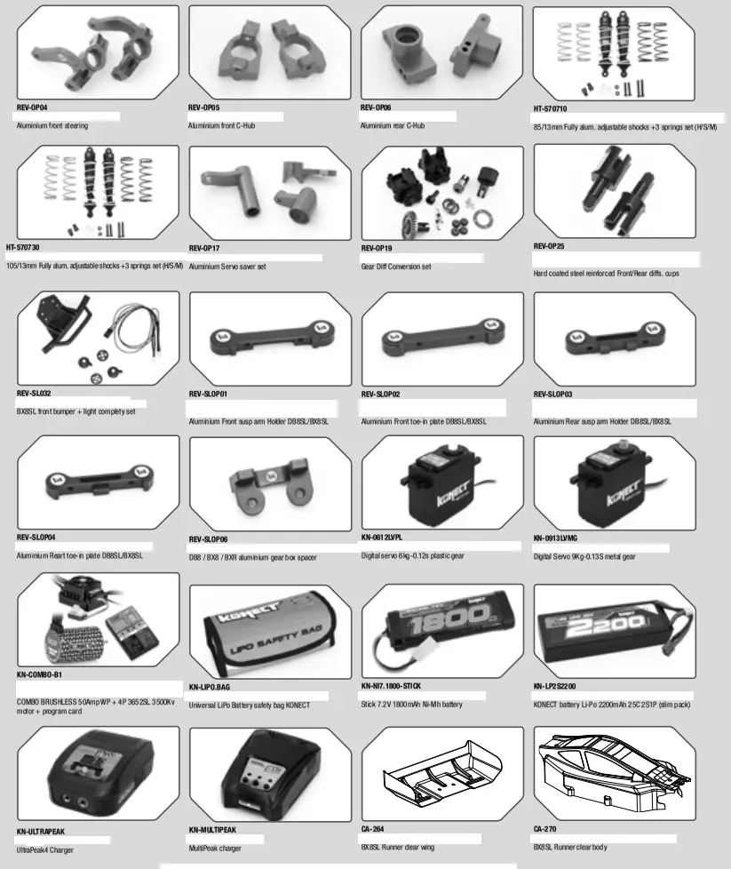
OPTION PARTS & UPGRADES
![]()
Specifications are subject to change without notice.
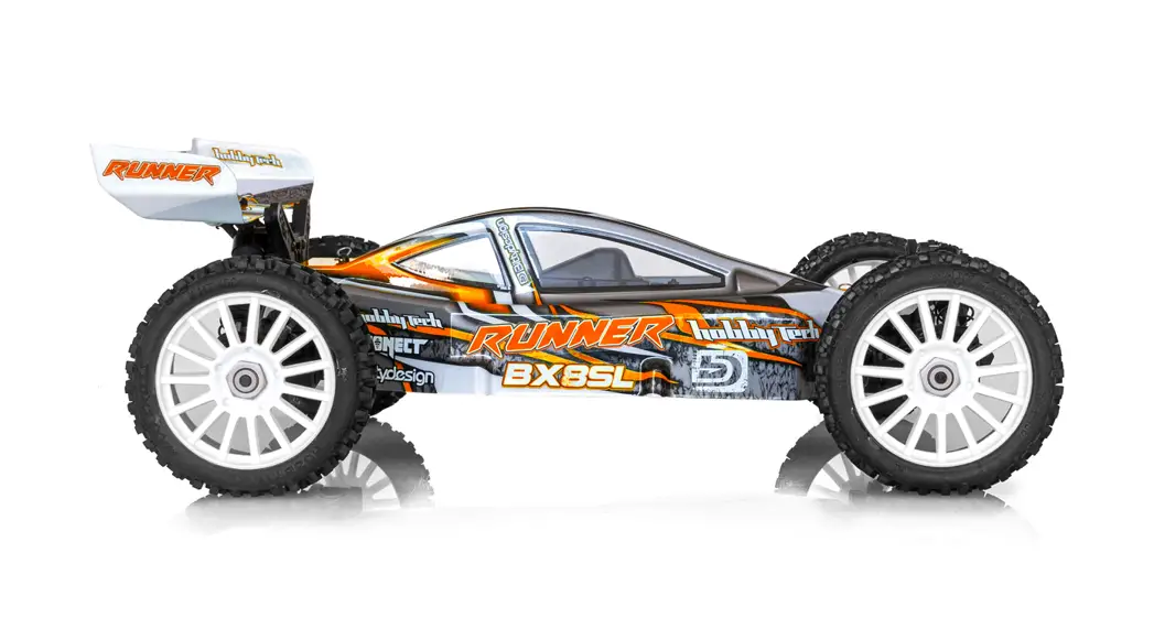
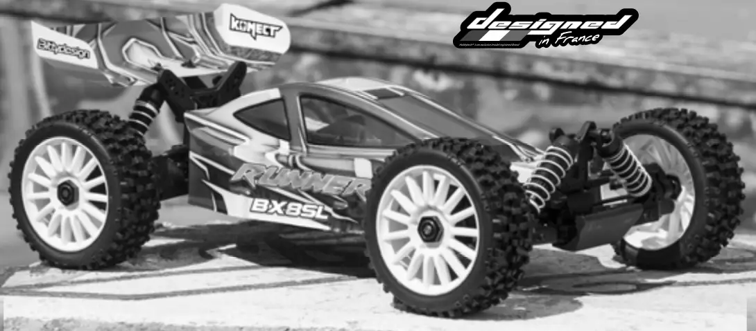
The photograph shows the model after assembly and painting.
[email protected]
General information


